CaseLabs STH10

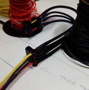
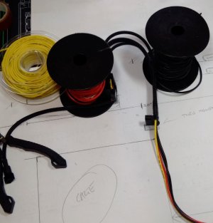
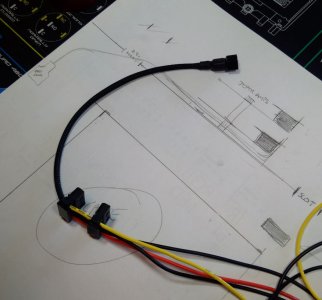
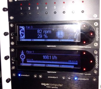
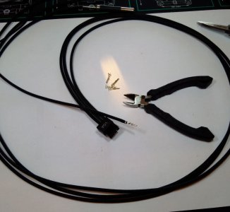
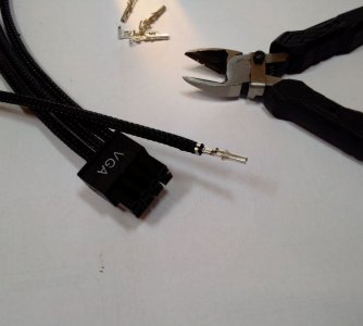
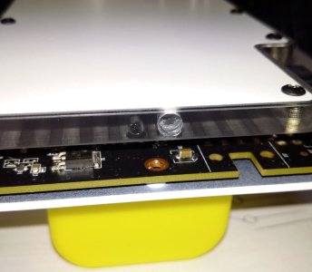
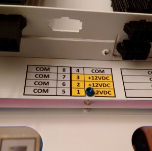
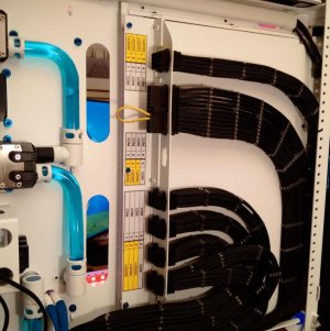
I already had one go at this cable but I was not happy with it, I had put a join in the middle to take one of those Molex male/ female connectors that has a 5v feed coming off.

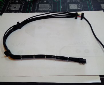
The 5v is for the USB hub but it just did not look very good so I bit the bullet and have done it again in one piece which is much neater.;

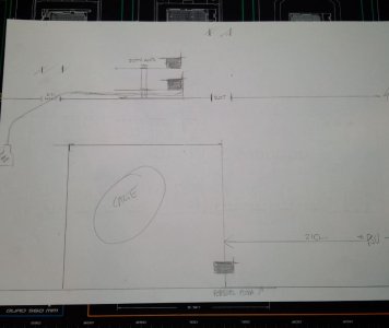
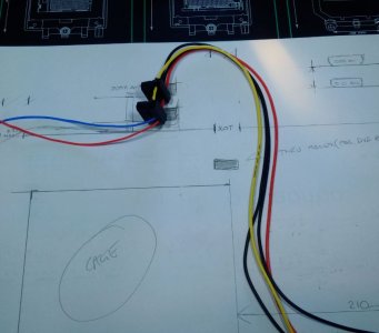
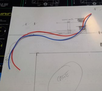
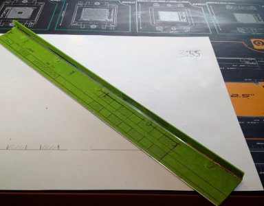
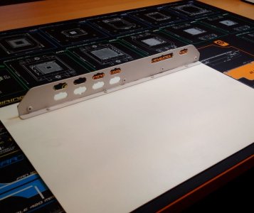
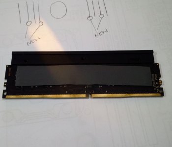
I sketched a full size section of the run needed for the cable with the critical points for connectors. This saved a lot of time going back and forth with a tape to the PC and is much more accurate.

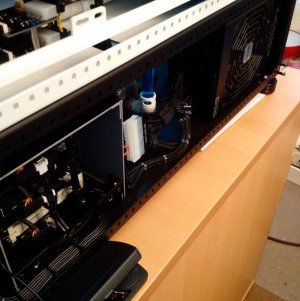
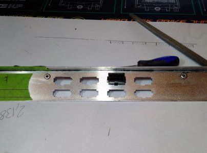
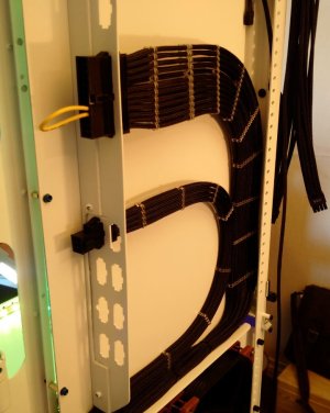
I think this is the most complex cable I have to make so glad to get it out of the way. It fits too; which is always a bonus :D
 

Attachments

  • FullScaleCrossSectionForMolexPowerCables.JPG
    FullScaleCrossSectionForMolexPowerCables.JPG
    52.4 KB · Views: 93
  • Template6.JPG
    Template6.JPG
    58.2 KB · Views: 102
  • Template5.JPG
    Template5.JPG
    66.9 KB · Views: 97
  • Template4.JPG
    Template4.JPG
    84.5 KB · Views: 90
  • Template3.JPG
    Template3.JPG
    58.2 KB · Views: 107
  • Template2.JPG
    Template2.JPG
    74.3 KB · Views: 89
  • Template1.JPG
    Template1.JPG
    63.9 KB · Views: 91
  • USB2_HubPowerCablesToLength.JPG
    USB2_HubPowerCablesToLength.JPG
    47.5 KB · Views: 81
  • Template7.jpg
    Template7.jpg
    82.5 KB · Views: 85
  • Template8.jpg
    Template8.jpg
    80.7 KB · Views: 103
  • Template9.jpg
    Template9.jpg
    80.8 KB · Views: 116
I have a pair of the iPPC F12's in my ITX rig and they are epic quality, the brown rubber parts are removable so you could quite easily make them all black if that offended you but I rather like it. They are stupidly high quality fans with 3-phase motors, the operating range is also incredible 250-2000RPM (although not officially that slow they really behave on Aquaero's!). I wouldn't jet wash the IP52's but the IP67's will withstand some abuse, if your the kind of person to run your fans underwater lol. The A14 design is airflow optimized however i'm sure they will still function reasonably well as radiator fans. I would definitely encourage the use of them in that style of build and black certainly looks better than cream.

Curiously have you purchased your radiators yet?

JR

Just to say thanks again JR23 for pointing me in the direction of Noctuas.

They do really perform on the Aqueros, for the first time tonight I played around with the touch screen and did a test setup on the lower radiator front 4 fans.

83 rpm is a cracking figure for a 2000rpm fan which was set up in a few minutes; I'm sure with more time and experience I could get them slower.
 

Attachments

  • 83RPM......jpg
    83RPM......jpg
    78.7 KB · Views: 85
3-phase FTW, man Aquaero's and Noctua's are awesome :) epic levels of stuff going on this build, can't wait to see it all start to come together.

JR
 
I made a hockey stick shaped bridge for the 24 motherboard cable to allow it to fit over the rear of the slide out motherboard tray and it worked well.

It was however not big enough to allow the GPU or CPU power cables to fit in the same area (I had forgotten about them when I was making it, doh.... :huh:)

Anyway back to the drawing board and looking at ease of changing the motherboard assembly I decided a bracket that will take 8 GPU sockets, a CPU socket and a 24 motherboard socket would be best.

This makes changing the colour of the cables seen in the motherboard chamber very quick and easy and if I decide to go 4 way SLI its just a case of plugging in a short extension cable.

Lots of drilling, filing and sanding later I have what is in the bottom picture. I am just waiting on some M3 nuts and bolts being delivered and a few more coats of paint and I will be able to fit it and wire up the sockets back to the PSU.
 

Attachments

  • MotherboardBridgeBrushed.JPG
    MotherboardBridgeBrushed.JPG
    90.3 KB · Views: 81
  • MotherboardBridgeCableExtensionSockets.JPG
    MotherboardBridgeCableExtensionSockets.JPG
    80.8 KB · Views: 92
  • MotherboardBridgeCableExtensionSocketsCutout.JPG
    MotherboardBridgeCableExtensionSocketsCutout.JPG
    71.6 KB · Views: 87
  • MotherboardBridgeCableExtensionSocketsFitted&Primed.JPG
    MotherboardBridgeCableExtensionSocketsFitted&Primed.JPG
    81 KB · Views: 90
I think this will be my last post for a few days, I have made a start on the 8 pin GPU cables and the 8 pin CPU cable.

These cables go from the PSU to the bracket I made yesterday which is still getting more coats of paint.

Each of these cables is just over 1m long so over 8m of sleeve and cable in each which takes a while to thread onto the silicon wire.
 

Attachments

  • GPU_CablesTheStart2.JPG
    GPU_CablesTheStart2.JPG
    78 KB · Views: 107
  • GPU_CablesTheStart1.JPG
    GPU_CablesTheStart1.JPG
    61.4 KB · Views: 85
Update

I got the Bridge fitted over the slide out motherboard tray and I have fitted the 2 cables shown.

I am still making the other 7 GPU cables, each with 8 wires and have 2 done so far today but I cant cut them to length and fit them because I am now out of Stealth combs. The combs should be here early next week by which time I will have the other 5 cables ready for fitting too.
 

Attachments

  • StartOfCablePSU_ToBridgeSockets.JPG
    StartOfCablePSU_ToBridgeSockets.JPG
    89.3 KB · Views: 111
  • StartOfCablePSU_ToBridgeSockets2.JPG
    StartOfCablePSU_ToBridgeSockets2.JPG
    85.2 KB · Views: 93
A little update and good news for Asus X99 E-WS owners, a company called Liquid Extasy in Germany has started making full cover water blocks for them.

I have placed an order for one like the picture below but in black derlin, not plexi.

It does mean that the bulkhead fitting in the bottom of the mobo chamber is now not in the right place (it was positioned to suit a simple CPU only water block in the centre)

I cant move this bulkhead fitting without massive re working of the loop/ drain off points so I will just have to live with a couple of extra bends to get the pipe plumb again.

I have noticed that the 2 PLX chips make the lower heat spreader very hot and have been hoping that someone would make a water block for the X99 E-WS but I had sort of given up hope!

I believe that these 2 PLX chips are what allows the x99 E-WS to have 7 PCIe 3.0x16 lanes, even with a 28 lane CPU, something to do with multiplexing which I thought was something to do with hanging around near cinemas.....:D

PS I have also ordered a set of XSPC RAM water blocks which match the GPU blocks and have the same LED lighting.
 

Attachments

  • X99 E-WS FULL COVER WATER BLOCK.jpg
    X99 E-WS FULL COVER WATER BLOCK.jpg
    75.3 KB · Views: 144
Last edited:
Extra RAM and the water blocks turned up today.

I was worried that the RAM would not work with the original RAM so I plugged it in and tried it before I install the side plates. It went fine, it has been installed and shows up as normal.

I took off the OC on the CPU and turned off XMP before I installed it to be on the safe side. Now its all back to normal with the mild OC and XMP running.
 

Attachments

  • RAM 2.JPG
    RAM 2.JPG
    52.1 KB · Views: 107
  • RAM 1.JPG
    RAM 1.JPG
    88.1 KB · Views: 77
  • 32gbExtraFitted.jpg
    32gbExtraFitted.jpg
    78.5 KB · Views: 83
  • 32gbExtra2.JPG
    32gbExtra2.JPG
    64.5 KB · Views: 94
  • 32gbExtra.JPG
    32gbExtra.JPG
    79.3 KB · Views: 88
I ran a few stress tests this afternoon with the Asus diagnostics utility to make sure everything was 100% with the new RAM.

It passed with flying colours so I took it out of my work rig and put the side plates on for when it goes in the new rig.

(I really hate that thermal tape stuff, sticks to everything apart from where you want it! :huh:)

I installed 2 of the modules in one orientation and the other two in the opposite orientation to the way the RAM clips into the motherboard.

This will allow me to have the XSPC logo on the outside of the two blocks of 4 modules when installed.

I like symmetry! Even if you cant see it, I will know its right....:)
 

Attachments

  • RAM6.JPG
    RAM6.JPG
    58.7 KB · Views: 85
  • RAM5.JPG
    RAM5.JPG
    48.6 KB · Views: 87
  • RAM4.jpg
    RAM4.jpg
    82.8 KB · Views: 83
  • RAM3.JPG
    RAM3.JPG
    91.1 KB · Views: 82
A bit more of the wiring and sleeveing done.

I am letting the wire and sleeve settle for a few days and then I will tidy it up a bit.

There are 2 more cables to go on this part, one more motherboard 8 pin and one more for the 6 pin PCI-E socket on the motherboard.

I will not be using 2 of the 8 GPU sockets at present but they are there to make it easy to plug in another GPU or other type of PCI-E card.
 

Attachments

  • GPU_CPU_MOBO_PowercableSockets.JPG
    GPU_CPU_MOBO_PowercableSockets.JPG
    91 KB · Views: 88
I decided the job for this weekend would be the XSPC razor waterblocks LEDs upgrade from simple single colour LEDs to RGB LEDs run from the Jeak Amps.

First I had to drill some 5mm holes in place of the 3mm ones that are standard.

Plan A was to try and enlarge the existing hole but the hard, brittle Perspex did not like that and a small bit splintered off :(

Thankfully this broken piece is covered by the metal plate on one side and the other part will be behind the sleeve that the RGB wires will be in.

Plan B was to drill new holes beside the 2 on each block, much better this time :)
I now have all 3 blocks drilled out which included having to take off and refit one block from the graphics card I installed a few weeks ago.

I will do the RAM blocks tomorrow and then start lengthening the RGB wires and sleeving them, leaving them long so I can cut them to length accurately once the blocks are fitted to the motherboard and it is fixed in the case.
 

Attachments

  • GPU_RGB_5mmHoles.JPG
    GPU_RGB_5mmHoles.JPG
    67.9 KB · Views: 69
  • GPU_RGB_Upgrade.JPG
    GPU_RGB_Upgrade.JPG
    51 KB · Views: 75
Funny how little jobs can turn into much bigger ones........

As planned I wanted to drill the 5mm holes in the RAM blocks today but when I was looking at them I realised that the Copper heat plate will not match anything else on the build.

I decided to give it a coat of black satin which I think makes it look much better. I used double sided tape to mount both plates on a baton which makes small items like these much easier to get all the sides painted.
 

Attachments

  • Ram_Assembled.JPG
    Ram_Assembled.JPG
    58.2 KB · Views: 56
  • RAM_Painted1.JPG
    RAM_Painted1.JPG
    63.7 KB · Views: 55
  • RAM_On_A_Stick.JPG
    RAM_On_A_Stick.JPG
    61.1 KB · Views: 59
  • RAM_Drilled.JPG
    RAM_Drilled.JPG
    41.3 KB · Views: 69
  • RAM_Masked.JPG
    RAM_Masked.JPG
    57.5 KB · Views: 61
Tidied up the power cables and labelled them.

I found enough stealth combs to cut and fit the second CPU power cable.

All that is left now is the PCI-E aux power cable which is the missing socket in the middle with the same pin out as the VGA cables.
 

Attachments

  • PowerSocketsNamed5.JPG
    PowerSocketsNamed5.JPG
    66.1 KB · Views: 57
  • PowerSocketsNamed4.JPG
    PowerSocketsNamed4.JPG
    79.3 KB · Views: 59
  • PowerSocketsNamed3.jpg
    PowerSocketsNamed3.jpg
    78.6 KB · Views: 68
  • PowerSocketsNamed.jpg
    PowerSocketsNamed.jpg
    85.8 KB · Views: 64
How long did it take for all that cable management? It's astonishing! A lot of dedication:)

I would guess around 16hrs all in :eek:
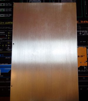
, I started making the cables over a week ago.

I need to get out more................:huh:

ETA, on the VGA/ GPU power cables, I have run all 8 wires from the PSU sockets to allow easy installation of new graphics cards in the future, the 970s I am installing in this are only 6 pin.

The question is; what is the point of 8 pin GPUs when the extra 2 pins are only common?
 
Last edited:
I finally decided what fittings I am going to use in the motherboard chamber area. All the pipework in the 2 loops is hidden apart from the pipes going to the mobo, GPUs, RAM and now the full cover water block for the mobo.

I like the free centre Monsoon fittings I have used everywhere else, they are quite slim and offer good grip for your fingers to tighten where you cant get a tool into. I wanted something different however for the on show mobo chamber.

I picked the black and white chain gun fittings because they match the case/ reservoir bases and the 2 fans in that chamber.

Those two colours are also pretty neutral, so with a change of fluid colour and sleeves to the mobo, I can update in the future.

They are also very nice pieces of engineering, a lovely finish and they weigh a tonne ! ;)
 

Attachments

  • MoboGPU_RAM_WaterblockFittings.JPG
    MoboGPU_RAM_WaterblockFittings.JPG
    74.9 KB · Views: 75
they're some beautiful fitting mate, i am loving how uniform this build is so for. keep the update's flowing
 
they're some beautiful fitting mate, i am loving how uniform this build is so for. keep the update's flowing

Thanks Tripp :D, here is todays update:

Before I install the mobo in the case and fit the 3 GPUs I decided I would install a Samsung SM951 M.2X4 ssd in the slot below the PLX chips heat sink.

I had to do it now or it would mean taking off the lower GPUs and a partial drain down.

I am going to try and put the OS on this drive at the weekend, from what I have read its a tricky thing to do but can be done with a bit of hassle.

It has quite impressive read and write speeds which nearly match the advertised figures which is unusual!
 

Attachments

  • M.2a.jpg
    M.2a.jpg
    76.7 KB · Views: 56
  • M.2b.JPG
    M.2b.JPG
    59.9 KB · Views: 55
  • M.2c.jpg
    M.2c.jpg
    94.8 KB · Views: 60
  • M.2d.JPG
    M.2d.JPG
    55.2 KB · Views: 58
  • M.2e.JPG
    M.2e.JPG
    94.6 KB · Views: 53
  • DiskMark18-6-15.JPG
    DiskMark18-6-15.JPG
    48.8 KB · Views: 56
Last edited:
Back
Top