CaseLabs STH10

A bit of a disaster today :( 
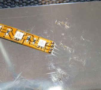
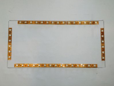
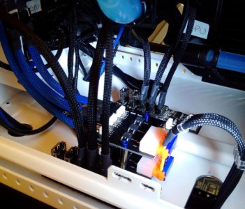
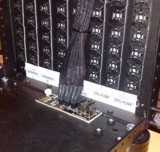
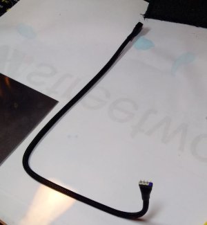
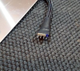
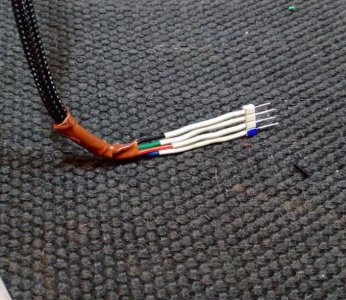
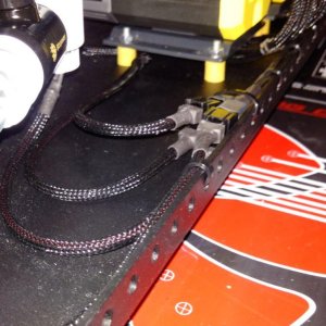
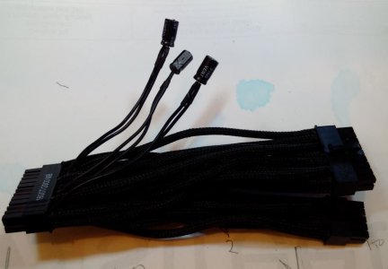
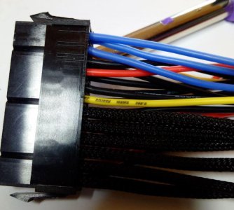
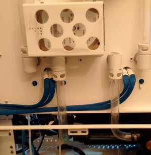
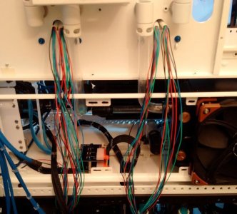
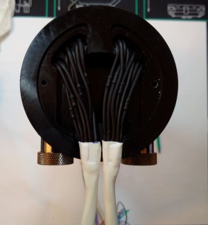
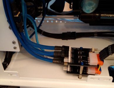
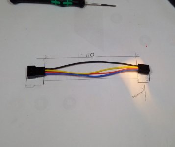
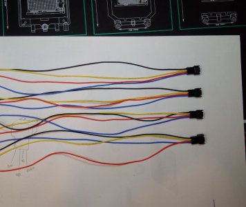
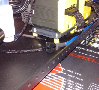
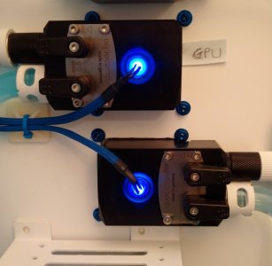
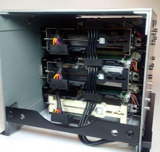
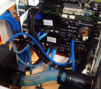
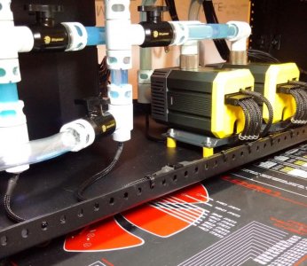
I have run out of black sleeve again (Note to myself - Order plenty next time, don't be so tight!) so I decided to wire up and sleeve the LEDs from the reservoirs and the filters to the Multiswitch.
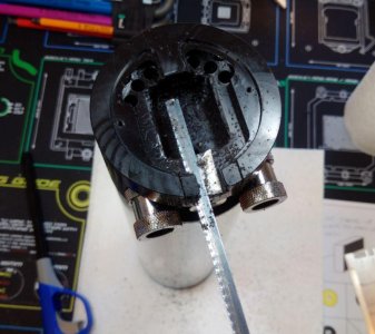
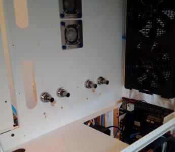
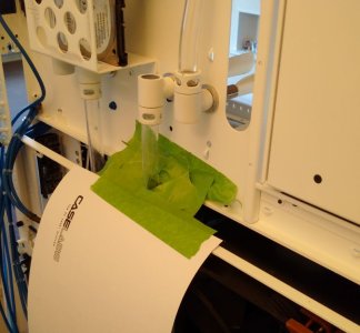
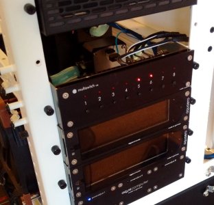
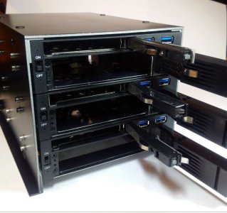
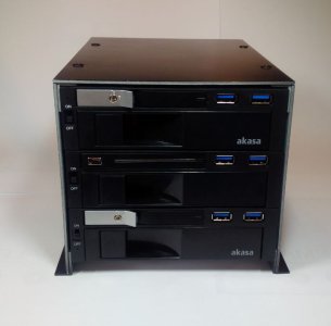
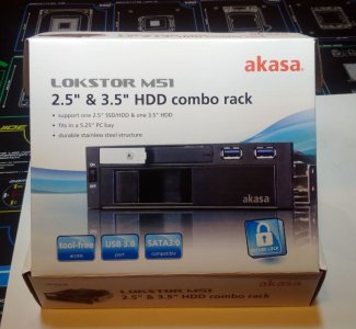
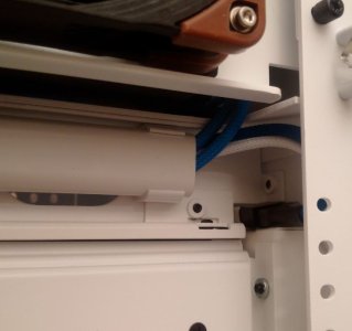
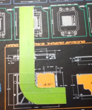
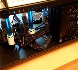
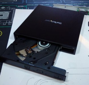
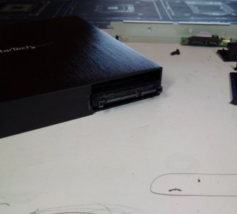
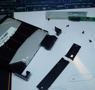
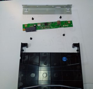
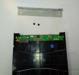
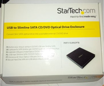
After installing 2 jumpers on the Multiswitch to turn off the PWM function and make the buttons on the front active I started connecting everything up.

All was going well, the reservoirs looked pretty cool lit up from inside with their normal LEDs. Then I extended the wires on some UV LEDs for the filters.

The first went in ok and I switched it on - no problems. When I was temporally attaching the second filter LED to the firsts sleeved cable I noticed that the resistor in the first LED was hot.

Very hot, so hot that I could not hold it between my "sleeving thumb and finger" which is used to molten plastic!

I first thought it may just be a faulty resistor so I continued on with the other UV LED and once fitted turned it on too.

After a cup of tea I came back to find the second UV LED out. I checked everything over and it looked fine but the resistor on this LED was also now super hot. Looking at the normal LEDs in the reservoirs I realised I had a problem, 5 of the 12 bulbs were out.

I then thought too much voltage so checked the terminals with my multi-meter and they were al just under 12V I then checked one of the Molex connectors on the LEDs that I had cut off to extend the wiring and I saw the problem, it was wired to the 5V side of the Molex connector.

I went through all the spare LEDs I have and they are all wired to the 5V side of the Molex sockets.

As the Multiswitch is going to be used for nothing other than a manual switch for the UV and normal LEDs I swapped the 12v and 5V wires over in the power supply Molex and plugged it in. I seems to work, all the resistors are now just mildly warm which I hope is normal.

Do any of you who know about these things see any problem with what I have done with the Multiswitch power supply? I don't want to burn the house down........ anyone?
 
Last edited:
I was going to have to replace all 12 LEDs in the reservoirs due to the problems I had this morning so while I had the reservoirs off I thought I would use some of the RGB LEDs I got with the Jeak AMP.

24 wires in each Aquqtube was a tight fit! I had to cut back the slot at the rear to get enough room for both groups of wires.

4:1 heatshrink tightened the bundles of wires as much as they could be and let me fit the metal plate over the bottom of the reservoir.

I also had to enlarge the holes behind the reservoirs with my step drill to allow the 4 pin connectors to pass through.

(I did not want to take these connectors apart, how Jannik managed to get 4 wires into each tiny fan terminal is unbelievable, respect! I did not want to chance breaking one by taking it apart!)

I have sleeved all 4 bundles with E22 SATA sleeve which expands well over the 4 pin fan connectors that these LEDs use.

With the nearly clear UV X1 fluid I now have to fill the loops and this amount of powerful LEDs in each reservoir, the liquid should really show off the colour that will be heat dependant; blue for cold, red for hot etc.
 

Attachments

  • EnlargingLED_AquaTube.jpg
    EnlargingLED_AquaTube.jpg
    76.9 KB · Views: 120
  • TidiedUpWires.JPG
    TidiedUpWires.JPG
    63.5 KB · Views: 120
  • LotsOfWires.jpg
    LotsOfWires.jpg
    84.9 KB · Views: 115
  • ReservoirsRemoved.JPG
    ReservoirsRemoved.JPG
    61.7 KB · Views: 109
  • EnlargingLED_WireHole.JPG
    EnlargingLED_WireHole.JPG
    69.8 KB · Views: 116
  • 6LED_HolesFilledWithRGB_LEDs.JPG
    6LED_HolesFilledWithRGB_LEDs.JPG
    57.7 KB · Views: 119
  • 4-1_HeatShrink.JPG
    4-1_HeatShrink.JPG
    59.4 KB · Views: 110
  • EeekWires.JPG
    EeekWires.JPG
    87.4 KB · Views: 116
With not wanting to take apart the LED lights connectors I had to make up some short cables to get 2 of them to reach the AMP (I got lucky with 2 of them, they were the perfect length for my wiring route)

I find with a cables this short it is worth drawing a full scale sketch to work to. On long cables 10-15mm too long will not really be a big deal, you can loose that amount in a bend. On short cables it makes a much bigger difference.

I used the same E22 SATA sleeve which fits over the 4 pin fan connectors. After sealing the cut end, I snip it lengthways up the sleeve to help them expand over the connectors. (The sleeve does not fray when you cut in that direction)

I have 1 spare output on each Jeak AMP, from which I can run 4 LEDs. I am leaving them empty at the moment I may use them at a later date.

With these RGB LEDs in the reservoirs and RGB LED strips running from the AQ Farbwerk Amps it should be possible to have the case lighting match any colour scheme that I may change it to in the future.

ETA.

Having burnt out the normal LED lights I fitted yesterday in the filters I had to replace them with new ones. While doing this I also ran wires to the pedestal for the 2 Monsoon Rotary Light Ports and the same in the top chamber light port rotarys.

I have left these wires short in both chambers and fitted them with 3 pin fan female sockets (with the outer pins connected; one to the power and one to the negative) so that I can more easily change the LEDs in these fittings without having to rewire back to the Multiswitch. I will fit the LED lights with male 3 pin fan connectors to match.
 

Attachments

  • JeakAmpLED_WiredUp.JPG
    JeakAmpLED_WiredUp.JPG
    75.8 KB · Views: 115
  • B&Q_CableTieHolders.JPG
    B&Q_CableTieHolders.JPG
    58.6 KB · Views: 117
  • 3-1_HeatShrinkInPlace.JPG
    3-1_HeatShrinkInPlace.JPG
    40.8 KB · Views: 125
  • CuttingSleeveToExpand.JPG
    CuttingSleeveToExpand.JPG
    51.4 KB · Views: 126
  • MadeToMeasure.JPG
    MadeToMeasure.JPG
    32.1 KB · Views: 130
  • Tails.JPG
    Tails.JPG
    79.6 KB · Views: 117
  • LED_WiresIntoMultiswitch.jpg
    LED_WiresIntoMultiswitch.jpg
    88.7 KB · Views: 131
  • LED_WiresThroughToMultiswitch.JPG
    LED_WiresThroughToMultiswitch.JPG
    61.2 KB · Views: 135
  • LED_SocketsInPedestal.jpg
    LED_SocketsInPedestal.jpg
    91.6 KB · Views: 114
  • LEDsSwitchedOn.JPG
    LEDsSwitchedOn.JPG
    67.8 KB · Views: 114
  • FilterUV_LEDsMk2.JPG
    FilterUV_LEDsMk2.JPG
    70.2 KB · Views: 132
Last edited:
I got two more feed wires from 2 of the fan splitters in the top chamber wired back to the Aquero tonight. Not a lot to show really as most of the wire is hidden.

The third and final Akasa combo drive cage turned up today so I fitted that to the frame I made.

I am really pleased how this has turned out, the cage can hold 3 SSDs and 3 HDDs which when combined with the 4 SSD cage on the back of the case should be more than plenty for my needs.
 

Attachments

  • 3SwitchedPowerSupplys.jpg
    3SwitchedPowerSupplys.jpg
    76.3 KB · Views: 112
  • 3_SSD&3_HDD.JPG
    3_SSD&3_HDD.JPG
    96.8 KB · Views: 106
  • MolexPowerSupplyScocket.JPG
    MolexPowerSupplyScocket.JPG
    53.6 KB · Views: 123
  • 3AkasaComboCageFanFitted.JPG
    3AkasaComboCageFanFitted.JPG
    52.5 KB · Views: 139
  • 3AkasaComboCageFrontSide.JPG
    3AkasaComboCageFrontSide.JPG
    56.9 KB · Views: 126
  • 3AkasaComboCageRear.jpg
    3AkasaComboCageRear.jpg
    80.8 KB · Views: 138
  • 3AkasaComboCageFront.JPG
    3AkasaComboCageFront.JPG
    43.1 KB · Views: 129
  • AkasaComboBox.JPG
    AkasaComboBox.JPG
    85.4 KB · Views: 131
  • TopChamberFans2SplitterWiresToAquero.JPG
    TopChamberFans2SplitterWiresToAquero.JPG
    43.3 KB · Views: 122
  • 2MoreFanSplittersConnectedToAqueros.jpg
    2MoreFanSplittersConnectedToAqueros.jpg
    92.1 KB · Views: 127
In this build one thing I had decided not to fit was a DVD drive, I don't really use one but the more I thought about it the more I realised it would be worth having "just in case"

I did not have a lot of room! ;) For a full size DVD drive and I did not want to put it in the front of the case so the only real option was a laptop slimline DVD inside the case within an external enclosure to keep it clean.

I got all the bits today so I just had to make a couple of alterations to the enclosure to remove the USB PCB and then cut back the rear cover to allow the mini SATA to normal SATA adapter fit, ready for the power and the SATA cable from the MoBo.

It is going to be fitted on top of the SSD & HDD cage and with its black aluminium finish should blend in well.

ETA. Also got the LEDs wired up and working in the Monsoon light ports along with shortening the temp sensor wires and fitting them to the 2 pumps with new connectors.
 

Attachments

  • Drive_Enclosure7.JPG
    Drive_Enclosure7.JPG
    58.2 KB · Views: 116
  • Drive_Enclosure6.JPG
    Drive_Enclosure6.JPG
    73.1 KB · Views: 122
  • Drive_Enclosure5.JPG
    Drive_Enclosure5.JPG
    52.4 KB · Views: 116
  • Drive_Enclosure4.JPG
    Drive_Enclosure4.JPG
    85.1 KB · Views: 99
  • Drive_Enclosure3.JPG
    Drive_Enclosure3.JPG
    63 KB · Views: 105
  • Drive_Enclosure2.JPG
    Drive_Enclosure2.JPG
    59.7 KB · Views: 128
  • Drive_Enclosure.JPG
    Drive_Enclosure.JPG
    78.9 KB · Views: 122
  • LightPortLEDs&TempSensors_WiredIn.jpg
    LightPortLEDs&TempSensors_WiredIn.jpg
    91.7 KB · Views: 118
Last edited:
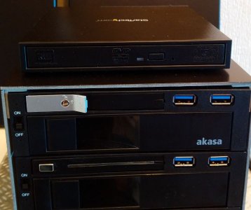
You have serious patience. I'm jelly! Great job on all that wiring!

Thanks again Bartacus

Wow fuck me is all I gotta say you have some killa skills that is a piece of technical art haha
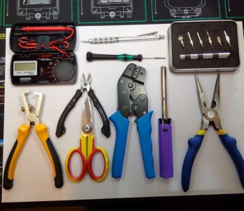
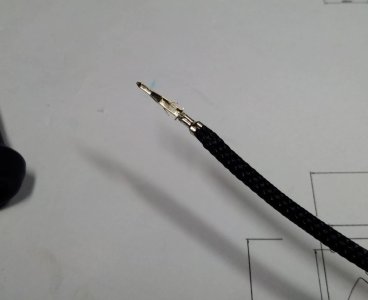
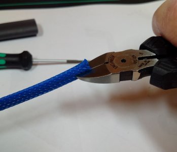
Thank you too.

Small Update:-

Had a change of plan with the sleeving, I did not like the way the blue and the black looked in the wires going to the Aqueros etc so I have re sleeved everything in Black apart from the flow meter wires which I still have to do. I will probably also re sleeve in black the RGB LED wires from the Jeak Amp too when the E22 SATA sleeve I ordered yesterday gets here.

Its a bit of a mess in that area at the moment but its not worth sorting it out until all the wires are in place. When they are all in place I can sort out where they cross over and hold them together with cable ties both for looks and also to hold the connectors better in place on the pins. The USB cables in particular are very easy to disconnect by just touching the wire.

I still have 8 wires to add for the LED strips and quite a few temp sensor wires which thankfully most of which are too slim to make worth sleeving as they will be tucked away out of sight or ran in with something else.

All the USB2 cables have been made to measure, sleeved and now fitted to the hubs at one end and the pumps, Farbwerks and Aqueros at the other.
 

Attachments

  • USB2_ConnectedToHubs.jpg
    USB2_ConnectedToHubs.jpg
    89.2 KB · Views: 115
  • LotsOfWiresAqueros.jpg
    LotsOfWiresAqueros.jpg
    89.8 KB · Views: 108
I have moved the location of the USB hub, where I had it beside the JeakAmps and behind the Aqueros was just not working. Too many wires meant I could not reach through the wires to plug anything in or even properly see what goes where.

6 new custom length USB cables later and its now fitted in the pedestal and will be hidden by the HDD/ SSD drive cage.

I still have a lot of wiring to do on this build, I have one more fan cable to run from the top chamber top fans splitter to the aqureo.

Then I can start on the RGB LED strips and supply cables which I think I am going to make from scratch (Apart from the little plastic clip things that join onto the RGB Strip)

Its the only way I can see to get them sleeved neatly, the moulded on end fittings would mean 8mm, at least sleeve which will be too bulky to run around the case tidy.
 

Attachments

  • NewPositionFor_USB_Hub.jpg
    NewPositionFor_USB_Hub.jpg
    93.7 KB · Views: 91
No heat gun??? ALL that and you do it ghetto style with a lighter!? ;)
,

:D

I do have a heat gun that I used when I did my previous build with paracord but I find that it is too much for the PET sleeve and makes it swell which looks horrible.

ETA. Its a long nose candle/ stove lighter which I cant recommend highly enough.

They are so much more controllable than a normal ciggy lighter. You can see exactly where the flame is as your fingers are not blocking the view, if you know what I mean and if you have the flame on for a long time it does not burn your fingers.
 
Last edited:
I have got the other 2 light Port Rotarys fitted with their LEDs today and wired back to the Multiswitch.

As with the other 2 in the pedestal I have wired them up with fan connectors so that when a LED needs replacing in the future it does not have to be wired all the way back through the case.

I tried sleeving the RGB cables with 8mm sleeve as it was the size needed to fit over the large moulded on connectors at each end of the cable. It did not look very good, too bulky and to get the right length meant cutting the cable and a lot of soldering, holding back sleeve and generally a pain with only an ok looking result.

I also did not like the connectors onto the strips, in that they are very fiddly to take on and off the rgb strips if they need any work.

As with the LEDs I went with fan connectors. A short adaptor was made with a female 4 pin fan connector which made making the custom cables much neater.

The only problem was the other end of the wire where it has to connect to the Farbwerk.

I had some male to male RGB pin connectors and I tried to solder the 4 wires to the 4 pins but that just melted the connector.

I then had a stroke of luck, I had used a single core wire for these cables as I had it in the right colours and it turned out that the wire core was exactly the same diameter as the 4 pins in the connector.

I pulled the pins out of their plastic holder and pushed in the wire. A bit of blue permanent marker and heat shrink later and it worked a treat. It also fitted into the Farbwerk just a good as the original connector.
 

Attachments

  • RGB_CustomSleevedCable.JPG
    RGB_CustomSleevedCable.JPG
    29.1 KB · Views: 87
  • Trimmed&BlueHighlight.jpg
    Trimmed&BlueHighlight.jpg
    96 KB · Views: 83
  • NoSolderConnection.jpg
    NoSolderConnection.jpg
    97 KB · Views: 80
  • RGB_4PinFanConnector.JPG
    RGB_4PinFanConnector.JPG
    51.8 KB · Views: 84
  • 2MoreLedsInLightPortRotary2.jpg
    2MoreLedsInLightPortRotary2.jpg
    78.7 KB · Views: 89
  • 2MoreLedsInLightPortRotary1.jpg
    2MoreLedsInLightPortRotary1.jpg
    82 KB · Views: 87
I thought I would make up the 24 pin cable from the PSU to the rear of the motherboard over this holiday weekend. Starting this morning I cut the sleeve and cable ties off the cable that came with the PSU.

First thing I noticed was 3 capacitor type things which were under the sleeve before and out of sight. I also noticed that the 2 part connector that plugs into the PSU was not 24 pins, it was 28 pins which, with a lot of crossing of wires and several, 2 wires into one then terminated in a normal 24 pin male connector that would plug into the motherboard.

I wanted this cable to be neat but with all these extra wires and capacitors it did not look like it could be, so I decided to shorten the supplied cable to contain all the crossing wires in the PSU area and fit individual sleeves to try and smarten it up as best I can.

To do this I had to take the connectors that fit into the PSU off so that I could get the shortened sleeved wires connected up with the minimum of twisting/ crossing.

To take these off like this also meant I would have to do an accurate pin out drawing. I used cable ties around one wire at a time (to ensure I made no mistakes tracing a small wire through a bundle of 28) and established what went where.

It took a while but it was worth it and I have put a screen shot of it below if it is of any use to any other Super Flower 1600w modders.

Once fitted to the PSU I went over all 24 pins with my multi-meter and they all matched the 24 pin outputs stated in the Super Flower manual so all good :).

A couple of cable ties and its about as neat as I can make it, the wires in this standard cable are 16awg, quite a bit thicker than the more normal 18awg gauge. (I think they may be this thick gauge because judging by the markings this cable is also used on the 2000W Super Flower 8Pack Edition PSU)

It means you cant get the sleeve into the end of the connector, it just wont fit. Heat shrink would also look untidy due to the way some pins have 2 wires going in opposite directions.

Thankfully this short cable will be covered up by the peripheral, 8 PIN MoBo and the GPU power cables. Now I can make up, what will basically be an extension 24 pin cable, which will be easier to make with pin 1 going to pin 1, pin 2 to pin 2 and so forth.
 

Attachments

  • Leadex1600W_28-24PinOut.jpg
    Leadex1600W_28-24PinOut.jpg
    34.1 KB · Views: 92
  • ShortMoboCableInPlace.JPG
    ShortMoboCableInPlace.JPG
    91.6 KB · Views: 82
  • ShortMoboCable1.JPG
    ShortMoboCable1.JPG
    52.2 KB · Views: 95
  • EstablishPinOuts1.JPG
    EstablishPinOuts1.JPG
    79.6 KB · Views: 96
  • EstablishPinOuts2.JPG
    EstablishPinOuts2.JPG
    84.1 KB · Views: 98
Last edited:
Todays update,

While I have been working on the 24 wire motherboard cable I noticed that because of the pull out motherboard tray I had nowhere to fit the cable without running it between the filters and the SSD cage.

I did not want to do this so I have made up a "bridge" which is shown below in the various stages of fabrication and finally trial fitted before it comes off to be painted white.
 

Attachments

  • SlideOutBridgeCountersunkTrialFit8.JPG
    SlideOutBridgeCountersunkTrialFit8.JPG
    64.3 KB · Views: 81
  • SlideOutBridgeCountersunk7.JPG
    SlideOutBridgeCountersunk7.JPG
    52.2 KB · Views: 77
  • SlideOutBridgeCountersunk6.JPG
    SlideOutBridgeCountersunk6.JPG
    49.1 KB · Views: 85
  • SlideOutBridgeFiled5.JPG
    SlideOutBridgeFiled5.JPG
    35.5 KB · Views: 81
  • SlideOutBridgeRoughCut3.JPG
    SlideOutBridgeRoughCut3.JPG
    74.5 KB · Views: 82
  • SlideOutBridgeMarked2.JPG
    SlideOutBridgeMarked2.JPG
    78 KB · Views: 74
  • SlideOutBridgeTemplate1.JPG
    SlideOutBridgeTemplate1.JPG
    50 KB · Views: 84
Big cases means long cables :)

The 24 wire motherboard cable is 1.3m long so that's 30+ meters of 18awg and 30+ meters of sleeve.

A warning.............Pulling sleeve down a cable that long can cause friction burns...................ouch :(

Anyway, yet again I have run out of black sleeve so half this cable is sleeved and the other half should be good to go tomorrow when the sleeve gets delivered.

Update, T

The black sleeve turned up in the post as promised today and I finished the other 12 wires
 

Attachments

  • 24Wires1.jpg
    24Wires1.jpg
    93.9 KB · Views: 81
  • 24Wires2.jpg
    24Wires2.jpg
    84.5 KB · Views: 85
  • 24Wires12Done.jpg
    24Wires12Done.jpg
    87.3 KB · Views: 87
  • 24Wires24Done.JPG
    24Wires24Done.JPG
    91.2 KB · Views: 74
  • CrimpedATX.JPG
    CrimpedATX.JPG
    37.4 KB · Views: 81
Last edited:
I had to take the front fans off to change their sleeve colour to black and while I had them off I decided to add a bit of colour..........I used soldered joints as I have had not much luck with the normal clip on fittings.

I fitted RGB strips behind the frame in the motherboard chamber using those 90 degree strips and clips. The clip type of fitting, in my experience with them, is very prone to not making a good contact. Any slight movement has caused them to loose their circuit.I am going to replace those corner connectors with soldered joints like the other ones; a bit of a chore but it will be much more resilient.

I bought a 5m long RGB strip and have been using that to cut lengths from, it works out much cheaper if you have a lot of strips to install.

Other things done this week include making up a custom USB2 sleeved cable from the hub in the pedestal to the mobo area. Still lots to do.........:)
 

Attachments

  • HeatshrinkedRGBs.JPG
    HeatshrinkedRGBs.JPG
    59.3 KB · Views: 90
  • RedTest.JPG
    RedTest.JPG
    48.6 KB · Views: 86
  • BlueTest.JPG
    BlueTest.JPG
    54.7 KB · Views: 94
  • GreenTest.JPG
    GreenTest.JPG
    57 KB · Views: 85
  • SecondJoined.JPG
    SecondJoined.JPG
    42.9 KB · Views: 78
  • SolderInPlace.jpg
    SolderInPlace.jpg
    81 KB · Views: 91
  • Intake FansTemplateRBG.JPG
    Intake FansTemplateRBG.JPG
    46 KB · Views: 79
  • IntakeFans3.jpg
    IntakeFans3.jpg
    89.7 KB · Views: 77
  • IntakeFans2.JPG
    IntakeFans2.JPG
    96.6 KB · Views: 89
  • IntakeFans1.jpg
    IntakeFans1.jpg
    88.3 KB · Views: 76
  • RGB_StuckToFanFilter.JPG
    RGB_StuckToFanFilter.JPG
    94.1 KB · Views: 77
  • ConnectorFitted.JPG
    ConnectorFitted.JPG
    45.2 KB · Views: 72
  • FrontFansLitUpWithRGBs.jpg
    FrontFansLitUpWithRGBs.jpg
    87 KB · Views: 86
Back
Top