Blade Runner
New member
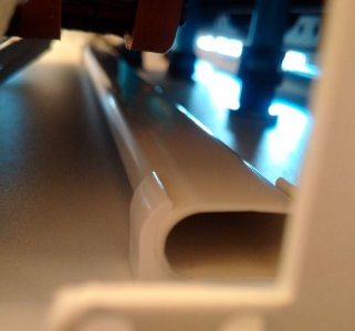
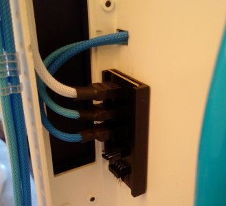
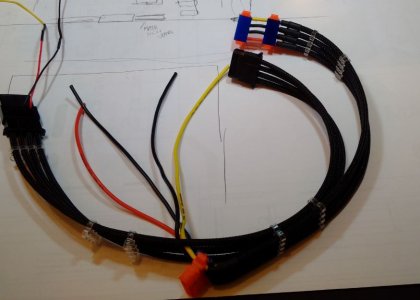
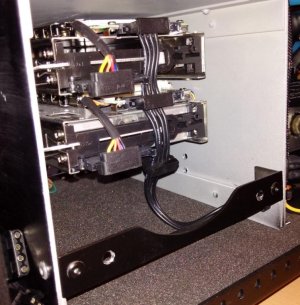
Nice job on those LEDs! There isn't much room in those channels for the wire. Nice work.
Thanks but I cheated a little
 . If you look closely you will see that I snapped off the inner "wall" of the channels to give a lot more room.
") .
.