Dawelio
Active member
I cant bring myself to add it all up with postage........
Umm... £300?

I cant bring myself to add it all up with postage........
I freakin' love this build! has to be my all time fave Caselabs build, everything so far is just how I'd have done it.

")
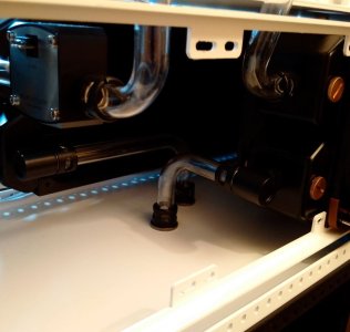
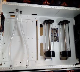
 well an idea I had, that I hope may work.
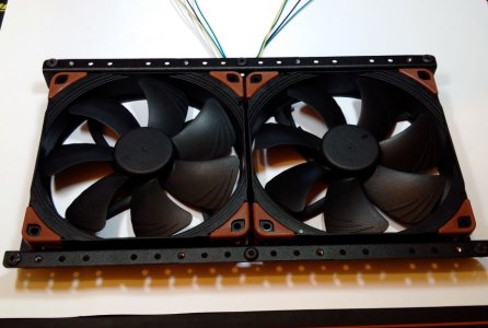
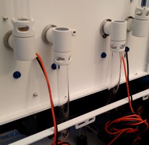
 Bring on the power cables
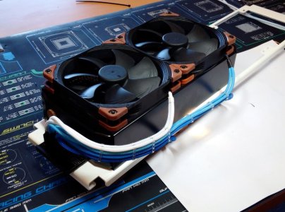
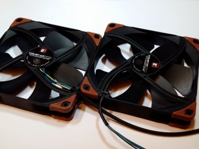
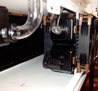
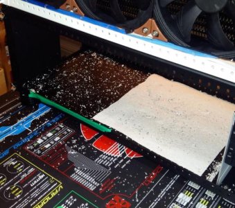
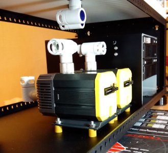
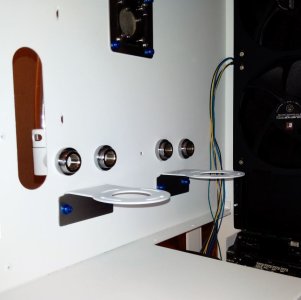
 What noctua fans are those?, NF-A14's Industrial?... how are they performing, have you tested them yet?, are they loud?...
As I used to have 2 NF-F12's Industrial 2000RPM PWM and they were so quiet when doing smaller stuff on the PC, but once I turned the PC on and they went full speed, I was like "Shit! The fuck is that?!... I thought it was the graphcis card first, but then realized it was the NF-F12's on the H100 lol.
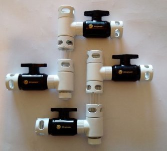
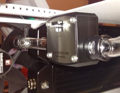
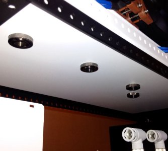
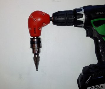
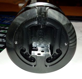
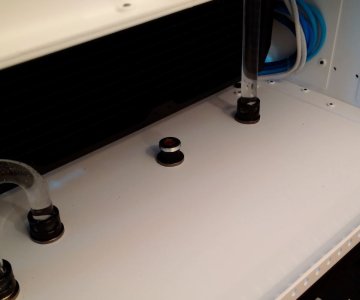
Nice job blade. Dont make my mistake. Ensure no spray got inside the fitting. any residue will wear off from the water flow/water heat and contaminate your loop. In my case, I had radiator white flecks build up in the CPU block which had worn off from some of my sprayed fittings and had a shitty performance hit on my loop.
I had to roll up some wet n dry and smoke that shi.. I mean sand the inside of the fittings to remove the paint. Even a couple of flecks was enough to annoy me.
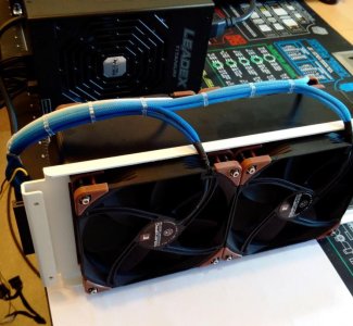
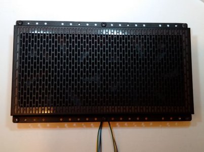
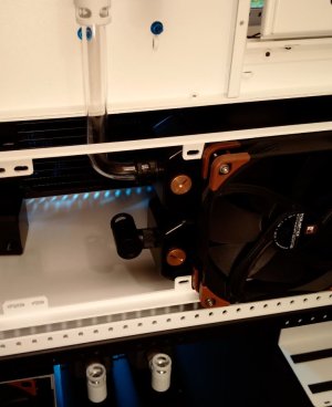
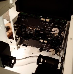
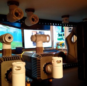
Never seen such an clean CaseLab build. Nice job love the fan wiring/cable management. Can't wait to view the complete build. Would love a video overview
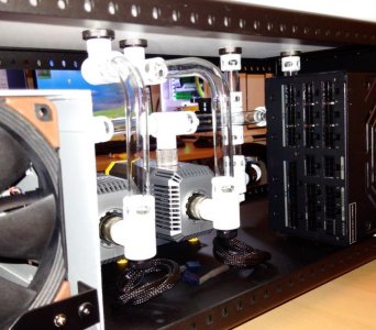
Hurry up please I wanna see more pics lol , I even bought more tissues .
But seriously it's coming together beautifully , super clean build , I really do envy this build on so many levels.