APOLLO (2CPU LGA1366 Server | InWin PP689) - by alpenwasser

Yummy, perfect SATA spacing, for once. :) I never understood why power supply manufactures always left so much bloody space between SATA connectors! HDD cages have been pretty much standard for spacing since the dawn of time.

Yup, I'm very much looking forward to seeing how it looks with some disks
in it. :D

And agreed, HDD spacing in most cases is ridiculous, you only need a little
bit of space and a little airflow so that the air doesn't just sit there and heat
up, that's it.


Also, the build has been share by MaximumPC on Twitter and Facebook
as well as on The Mod Zoo's FB feed. Yay!

(Is it OK to post these links here? If not, apologies.)

https://twitter.com/maximumpc/status/451821285924827136
https://www.facebook.com/TheModZoo/posts/538321302951013
https://www.facebook.com/maximumpc/posts/10152397893578885?stream_ref=10
 
Good to have you back around here with your awesome builds, looks mighty finefine..

Thanks mate, it is indeed.

Sadly I don't have as much time as I used to to just browse around forums
(well, I don't have as much spare time as I used to in general, hence why it
took so long to get this properly moving), but I have no intention of abandoning
ship. ;)
 
Chipset Cooling & Adventures in Instability

Chipset Cooling, Adventures in Instability


As some may be aware, I originally had some issues when trying to
get this machine to run stable. While stress testing with mprime,
it repeatedly and reproduceably crashed after less than an hour,
sometimes even already after a few minutes. Each time after
crashing, it took me several tries and about 10 to 20 minutes to
get the board to POST again.

After some troubleshooting and running a few diagnostics, it
turned out that the 5520 chipset was running really hot. It's
temperature threshold as indicated by the system is 95 degrees
Celsius, and when I was last able to check on it before a crash,
it had already passed 85 deg C, so I suspected that it was bumping
up against the threshold, upon which the board did an emergency
shutoff and mandated a cooldown period until it would run again.

As an emergency fix, I took the 80 mm San Ace fan that came with
the case and mounted it to the chipset heatsink with some waxed
cotton cord, and voilà somewhere slightly above 70 deg C maximum.
:)

Unfortunately I forgot to take pictures of that rather ghetto
setup before dismantling it again and replacing it with something
more solid, but I have managed to blow up some sections from
another picture that should at least give you an idea of how it
looked.


Some Improvisation

Apologies for the horrid picture quality, as said this is a blowup
from a picture of which this section is only a small part.
(click image for full res)


A More Permanent Solution

The chipset heatsink is just your run of the mill alu heatsink held
on by a spring clamp with some hooks.

(click image for full res)


And the naked chipset after cleaning off the TIM. That stuff was a
bitch to get off, it had dried up rather significantly.

(click image for full res)


Since the 80 mm fan is quite a bit larger than the chipset
heatsink itself, I needed to either replace the heatsink or modify
it in order to be able to mount the fan to it. I took a
rather crude, but very effective approach: I took an L piece of
aluminium, drilled two holes across the heatsink, cut some M4
threads on those two holes (which worked despite the holes only
going through the fins and not being continuous), then bolted the
L piece to the heatsink with two M4 screws. Works like a charm. :)

Don't mind the unclean alu bits from the drilling and cutting on
the heatsink between the fins, it wasn't really possible to
properly clean that off and make the holes as clean as one usually
does.

(click image for full res)


And from the other side...

(click image for full res)


The fan itself is held down by three screws, two in the L piece...

(click image for full res)


... and one in the corner of the heatsink itself. The bent fins
are from drilling and cutting the thread, they got a bit
structurally weak at their edges due to that. Doesn't impair
functionality, so not such a big deal since it won't be visible
anyway.

(click image for full res)


And the whole package:

(click image for full res)


The heatsink unit mounted on the M/B. You need to unmount the fan
to do that. You can again see the bent fins here.

(click image for full res)


And mounted, with the fan:

(click image for full res)


That's it for today, thanks for stopping by. :)


-aw
 
Maybe crude, but as long as it works and it's inside a server so wont be seen anyway so all is good :)

Precisely my line of thinking.


I must admit, I would have loved to make this build all pretty and such, I
even had a colour scheme: Powdercoat the interior black, make purple
custom cables. I think the purple might have gone well with the green PCBs
of all those server parts if it's the right shade.

But alas, it just doesn't really make sense from a financial POV (my dad is
paying for part of the build since he uses it for his business too), and even
if, I don't have the time at the moment to go that far with it.

Still, I have grown very fond of this machine and the mods I've done on it,
it might not be the prettiest thing ever, but it does get the job done, and
done well, which is what I set out to do above all else. :)
 
Disk Ventilation


Although disks have become quite frugal when it comes to
power consumption these days (at least some of them) and HDD
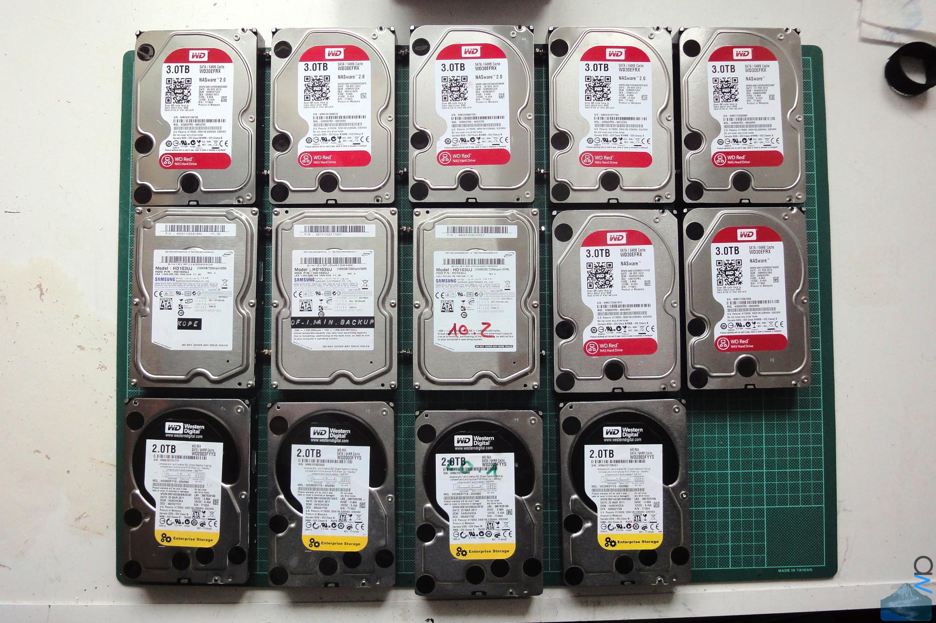
cooling is not really a huge issue for most people, packing
24 disks as closely together as in this build will cause
heat issues without ventilation. There is no need for 3k rpm
Delta fans though, a whiff of cool air breezing over the
disks should do the job nicely.

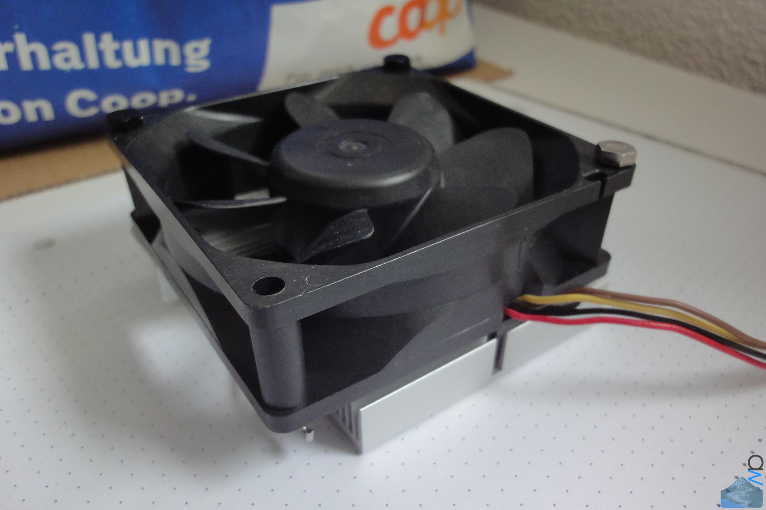
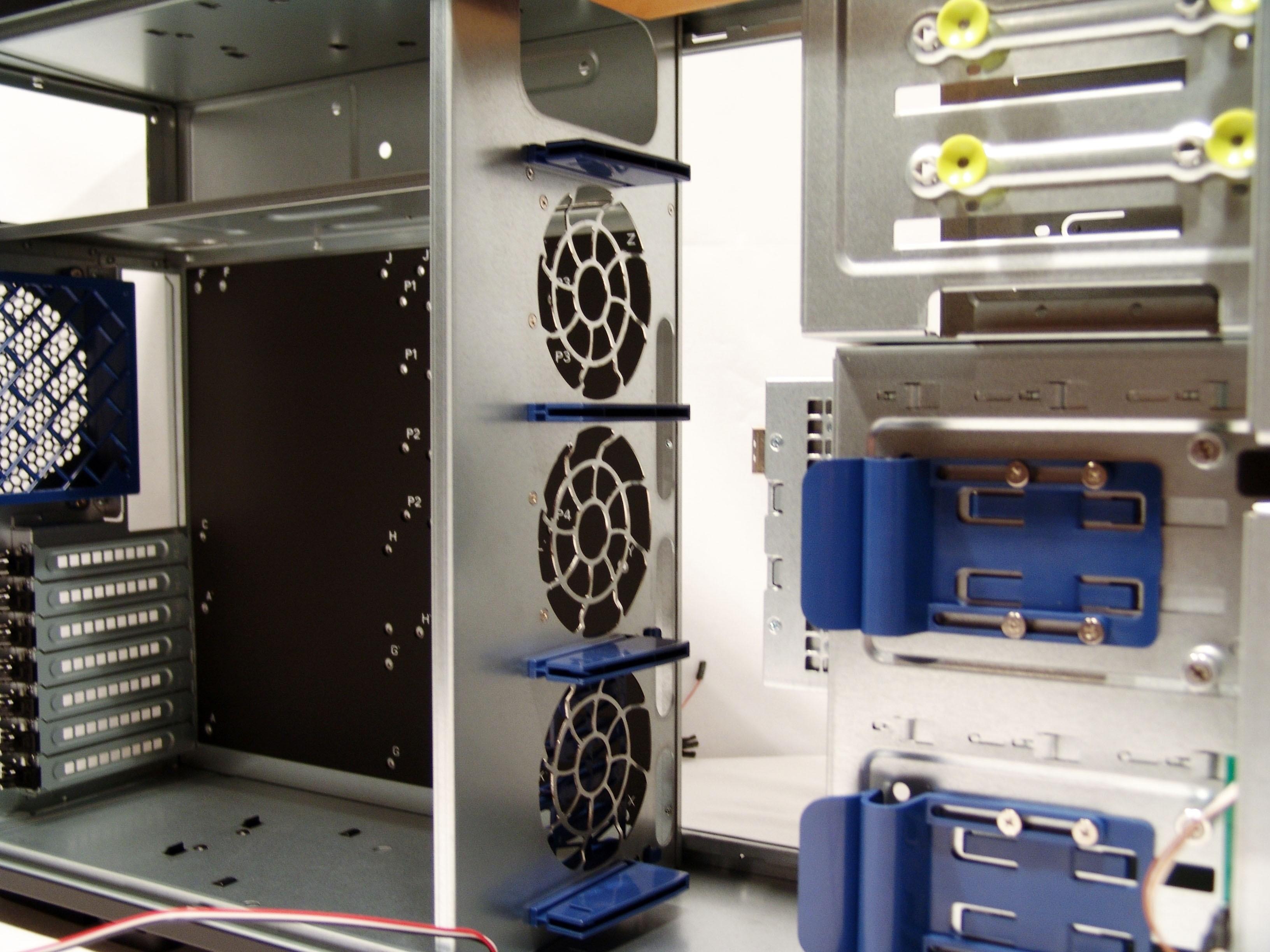
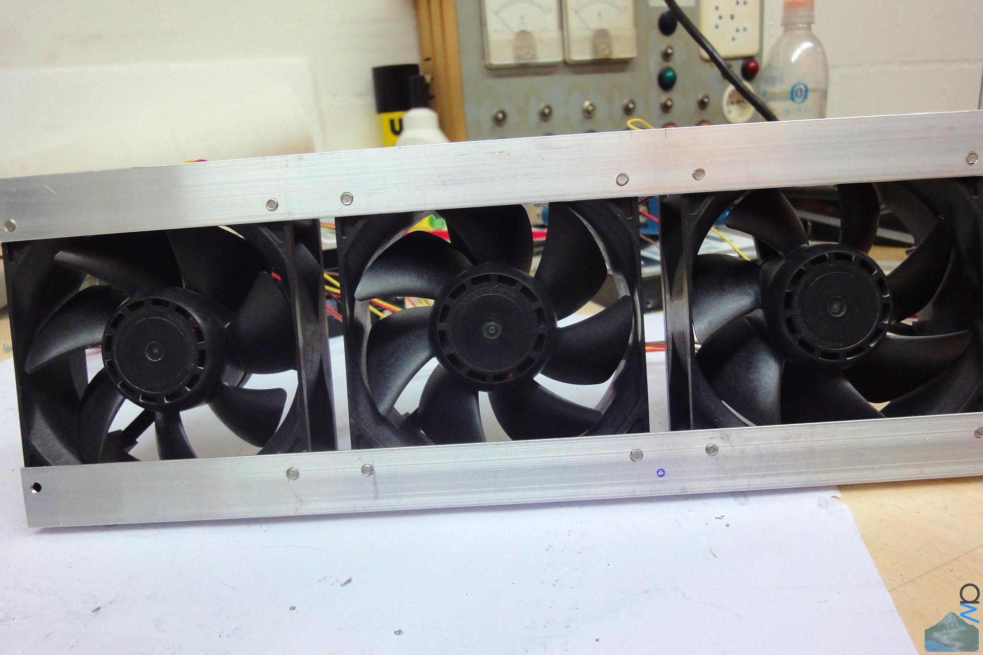
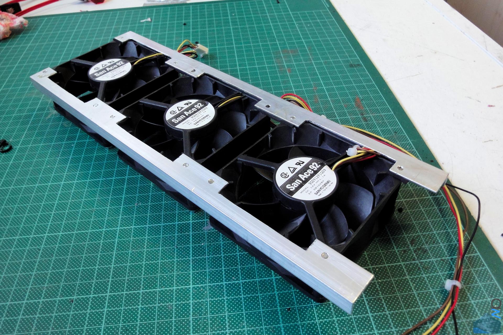
For this purpose, as you may have seen in some previous
pics, I have chosen 6 120 mm Papst fans, specifically the
4412 GLL model, and am running them at 7 V. The fans draw
air in through a vent area, and it then gets passed through
the M/B compartment and out the back.

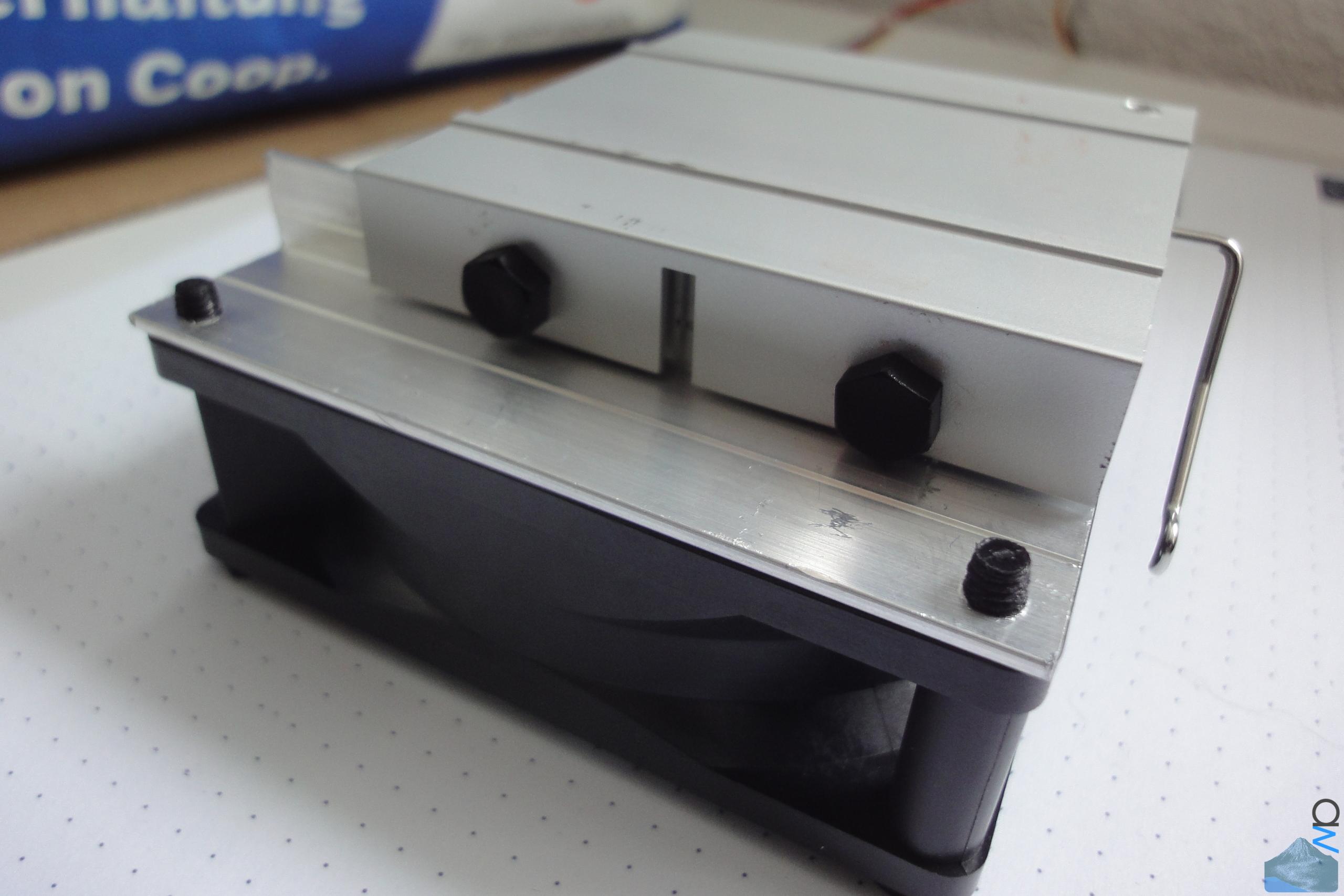
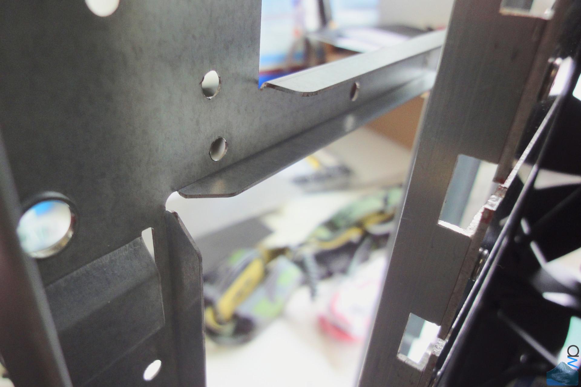
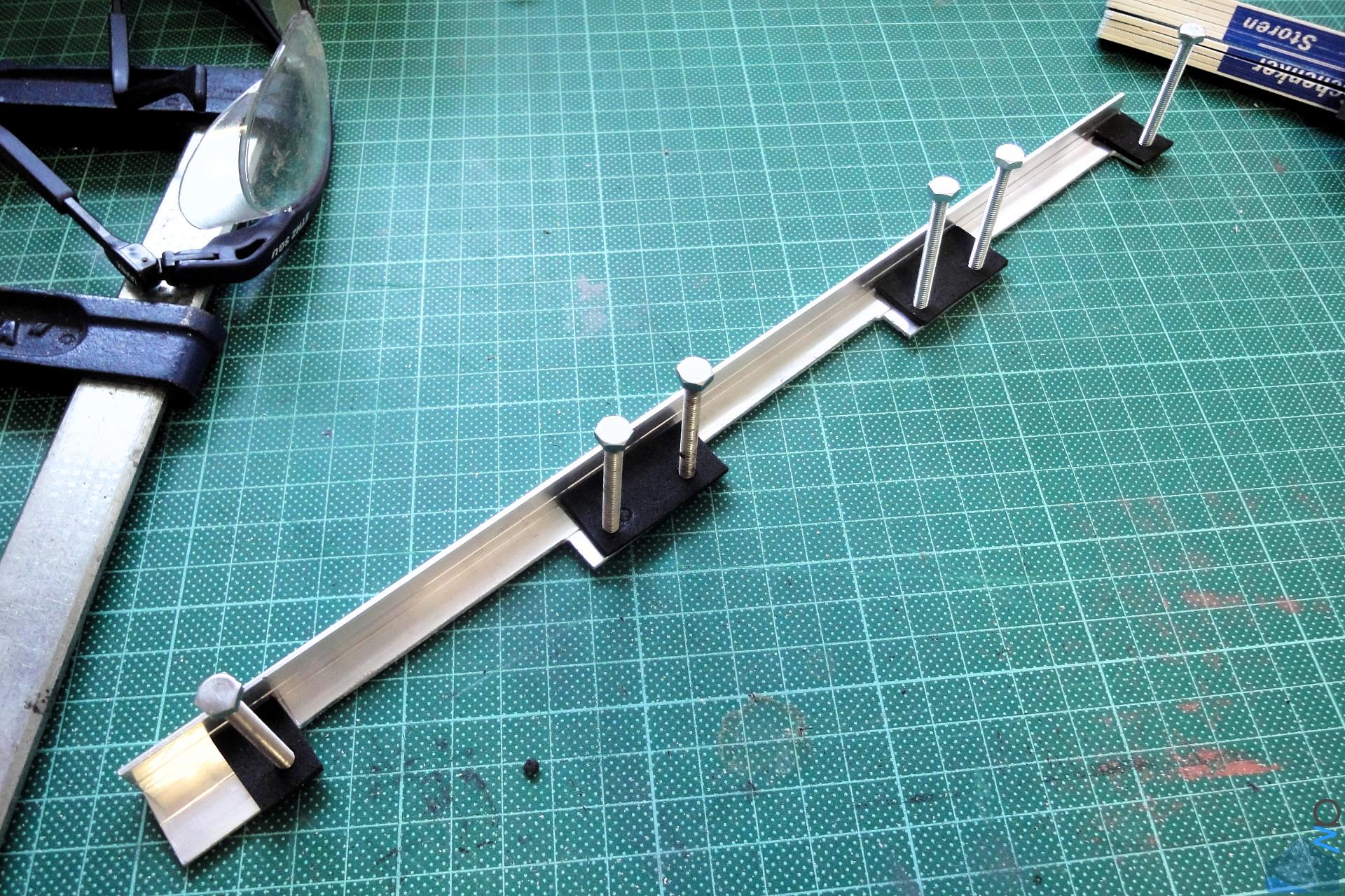
Each fan is fixed to a rail riveted to one of the disk rack
panels with two screws.


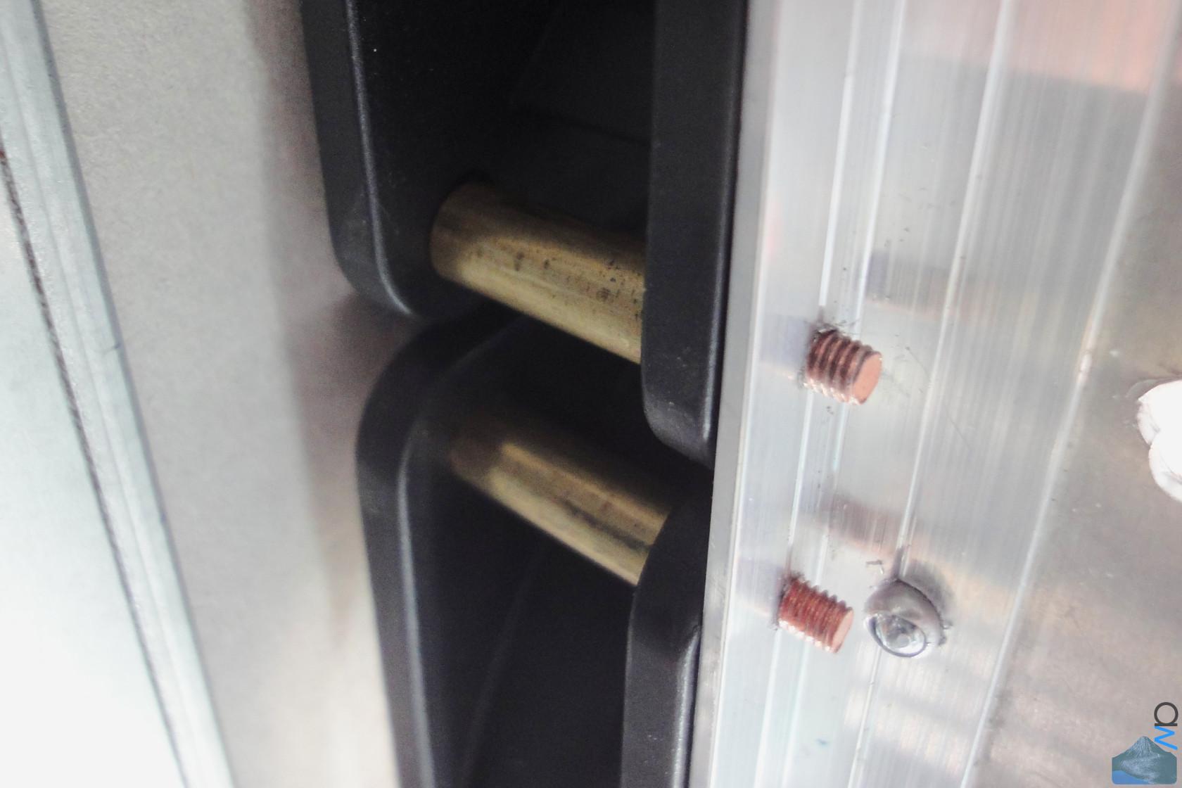
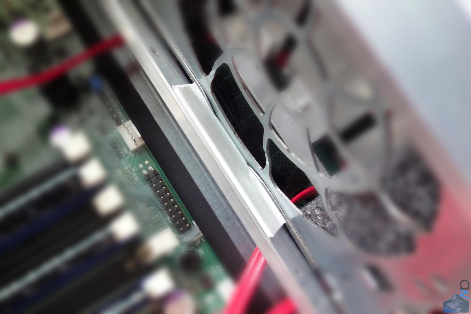
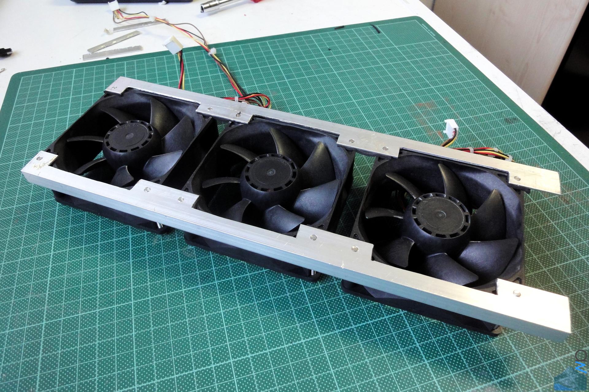
You've seen this before, but for completeness' sake I'm
adding the pics of the bushings used to prevent the fan
frames from being crushed to this update as well:

(click image for full res)


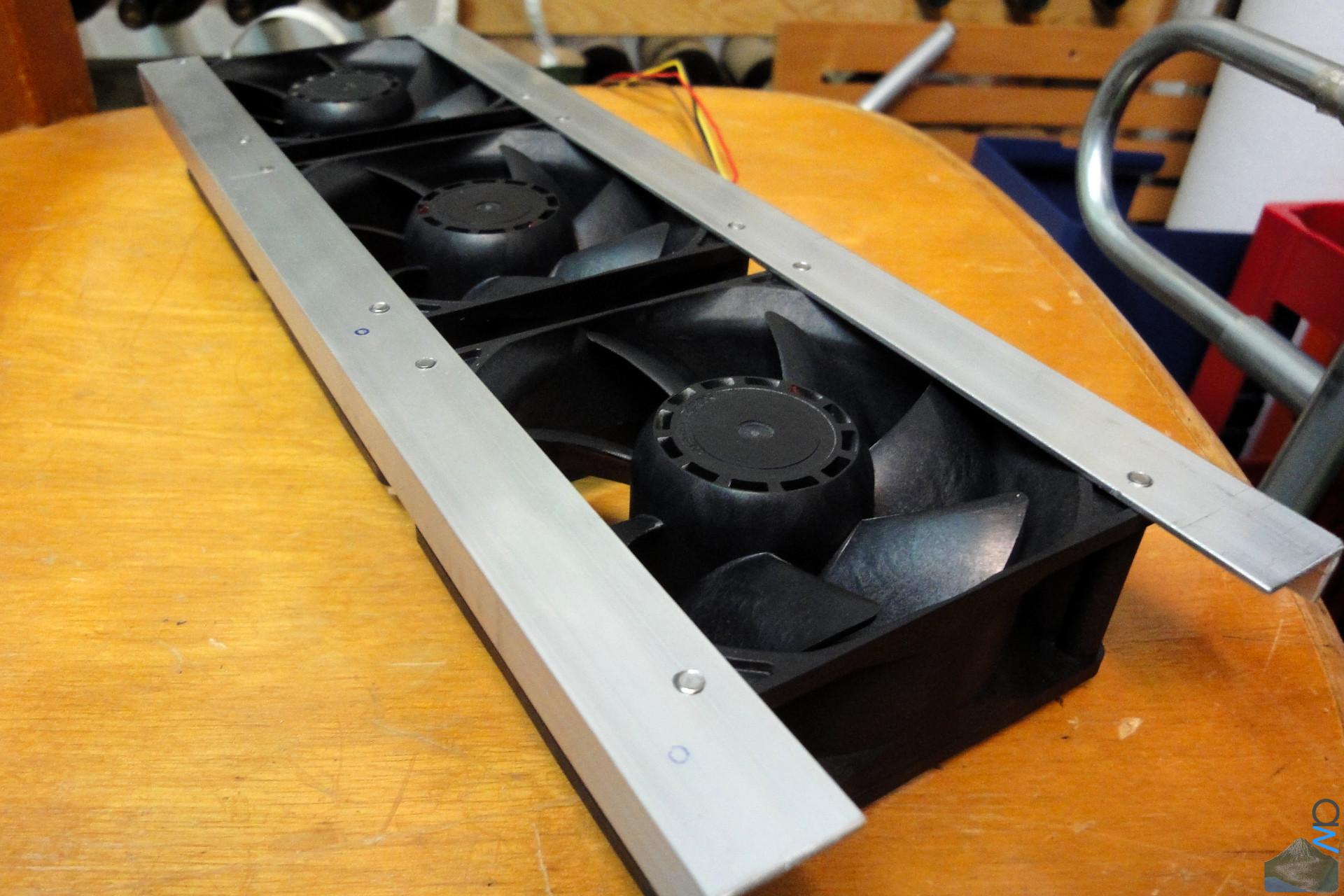
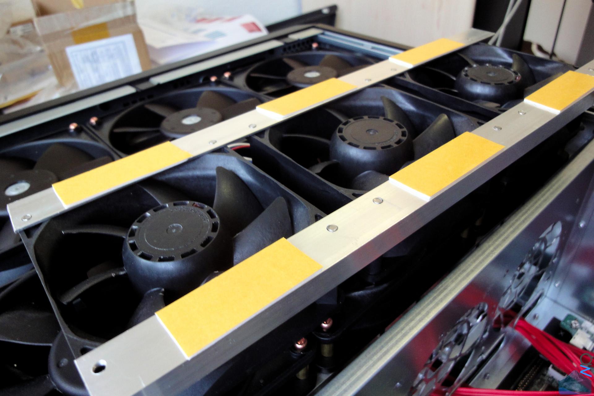
I exchanged the copper screws for some silver ones, and in
the process added some dampening foam between the mouning
rails and the fan frame.

(click image for full res)


The whole fan panel assembly:

(click image for full res)


While doing some test runs, I noticed that a rather large
amount of air was being expelled through the front of the
case instead of going into the M/B compartment and out the
back (I wasn't really surprised by this seeing as how open
the front was). Obviously, this was not optimal. So I took a
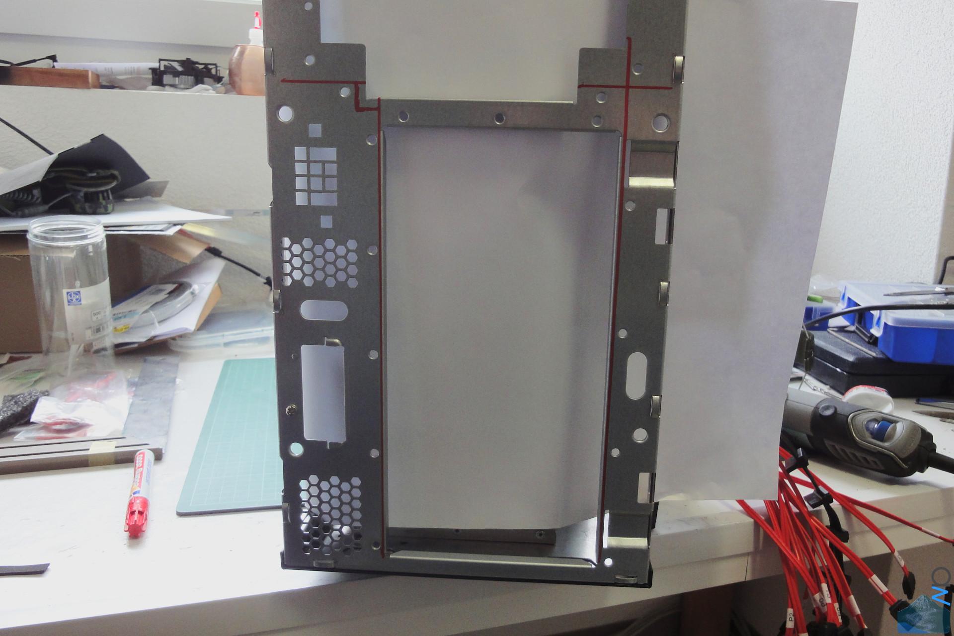
1.5 mm panel of alu and bolted it to the front.

Because the existing front has a few folds in it, I needed
to do some cutting on the case first.


(click image for full res)


(click image for full res)


(click image for full res)


(click image for full res)


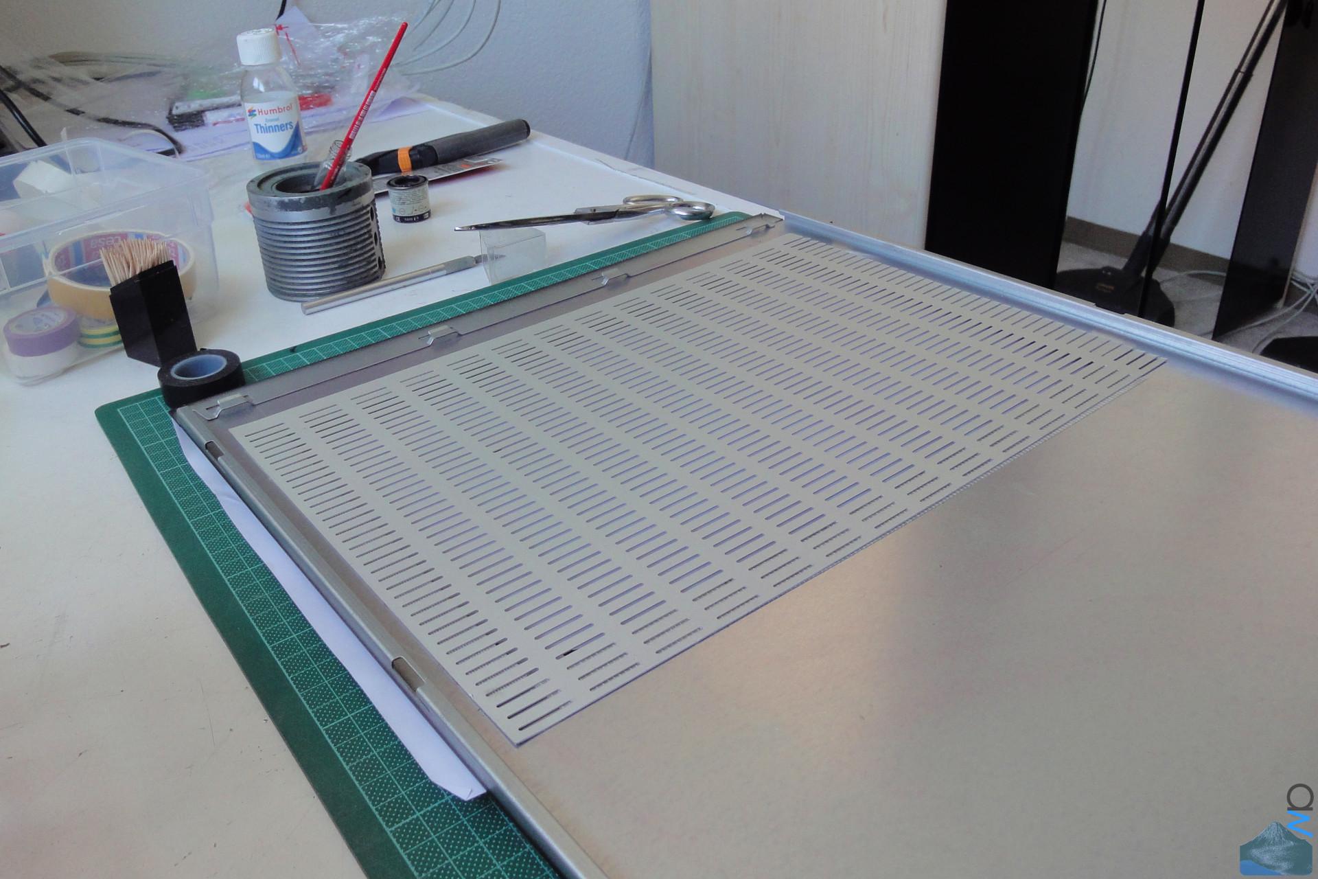
After having done that, I turned my attention to the side
panel, making an opening for the ventilation. I thought of
several ways of doing this, but all of them were a bit more
complicated than I'd have liked them to be. Cutting such a
big hole with a dremel isn't really practical, so I
considered doing it with our jigsaw, but after doing a few
test cuts I didn't really like the result as I couldn't get
a straight enough cut. And the cut needed to be clean,
because there's no space to fit a U channel over the edge,
and I don't really like the idea of covering it up on the
outside.

Anyway, the guy just used a nice big angle grinder for the
cut, and since he's a metal worker by trade, it turned out
almost perfectly straight (not 100%, but it's still cut by
hand, after all ;)). After that, I painted the bare edge
with some model paint to not have the blank metal staring at
me.

I thought about painting the mesh, but at the moment I don't
really have the time, plus I kind of like the look of this
bare piece of alu, so I've left it as-is.

(click image for full res)


The mesh doesn't cover the whole fan area (nor is it very
open with those rather narrow slots), but there is no need
for high-power ventilation here, so this is not a big deal.

(click image for full res)


It's fixed to the inside of the panel with some double-sided
adhesive tape.

(click image for full res)


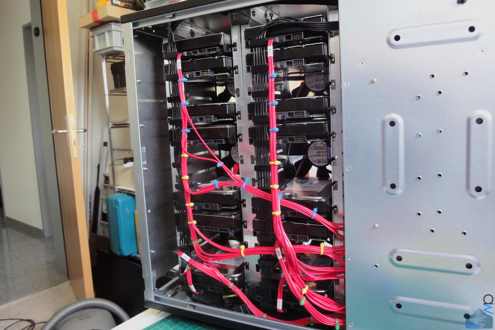
And in its final config:

(click image for full res)


Drive temperatures hover between 28 deg C and 35 deg C at
the moment, ambient is about 23 deg C. :)


Until next time,
-aw
 
I have to agree here. This is an Epic server build!


Thanks, much appreciated! :)

Anyway:

Triple Fan Unit


As hinted at earlier, the airflow in this build will go from
the front compartment through the middle wall into the M/B
compartment and out the back.

This is pretty much how the stock configuration works,
except in that the air gets in through the front panel, not
through the side panel.

Unfortunately I forgot to take pics of the stock config, but
luckily tweaktown.com did a review on this case and took them
for me. :D


Source article where I got the image from can be found here.

In the stock config, the 92 mm fans are mounted inside
some plastic fan cages that allow quick and toolless fan
replacement in case of failure.

(click image for full res)


And without the fan cages:

(click image for full res)


Originally I just screwed the fans to two aluminium L
profile bars.

(click image for full res)


(click image for full res)


(click image for full res)


It was fixed to the middle wall with double-sided adhesive
tape. It's very strong stuff, so the fan unit falling off
was not a concern. Additionally, the tape has some thickness
to it, which should provide some dampening between the fan
unit and the middle wall.

(click image for full res)


Unfortunately, due to some bumps on the middle wall getting in
the way, the tape on the rear angle didn't make proper contact
with the wall. It held, but not very well.

Additinoally, I noticed that there were rather strong
vibtrations on the middle wall. It turned out that the tape
did indeed offer some decoupling, but it also did not
offer any additional strength to the middle wall (i.e. no
additional stiffness), which meant the wall could easily
vibrate.

(click image for full res)


So, I took the unit out, and while I was at it, I also cut
out some recesses for the fans which I didn't bother doing
before. I also put some dampening foam between the fans and
the alu angles.

(click image for full res)


Aaand of course I mounted the fans the wrong way
round. Sigh.

(click image for full res)


Disassemble again, reassemble.

(click image for full res)


Also: Foam between the alu angles and the wall itself:
(click image for full res)


This time I bolted it to the wall with some screws. Much
more solid now, no more vibrations. :)

(click image for full res)


How it looks from the other side:

(click image for full res)


Cheers,
-aw
 
Storage Topology & Cabling

I see what you did there :lol:


lol, and I didn't even do that one on purpose. :D


Storage Topology & Cabling


Storage Topology


In case you can't read the text, the full res version should
be more easily readable.

(click image for full res)


The idea behind the storage topology is based on the concept
Any one of the three LSI controllers can fail and I still
have all my data available.

You'll see below that I haven't yet gotten around to
installing the Velociraptor.

I use coloured zip ties to mark the cables that go to the
different controllers.

BLUE = controller 0
YELLOW = controller 1
GREEN = controller 2


Tidiness

There isn't really any space to hide the cables, so this was
rather tricky and required three attempts until I was
satisfied with the result. In the end I hid the extra cable
behind the triple fan unit, good thing they're 38 mm fans,
which makes the space behind them just about large enough to
fit the extra cable bits.

The power cables for the disks are two cables that came with
the PSU and onto which I just put a lot more connectors
while taking off the stock connectors because those were
neither placed in the correct locations nor facing in the
right direction.


Looks harmless, right? Yeah...

(click image for full res)


And the disks:
(click image for full res)


OK then, first try:
(click image for full res)


I soon realized that this wasn't going to work. The problem
was that I had the disks arranged in the same way as the
will be set up in the storage pool layout, so the disks
which go into the same storage pool were also mounted below
each other. Sounds nice in theory, but if you want to
have disk from each pool distributed among the different
controllers, you'll get quite the cable mess.

(click image for full res)


(click image for full res)


Second Try

Next try, this time I arranged the disks to that the cables
to the controllers could be better laid out. Since I wanted
to set up all the cables for all the disk slots, even ones
that will stay empty for now, I had to shuffle the disks
around when laying out the cables.

(click image for full res)


(click image for full res)


(click image for full res)


Better. But I still wasn't quite happy, mainly because...

(click image for full res)


(click image for full res)


(click image for full res)


... of this:

(click image for full res)


Third Try


This time I made sure the cables stayed tidy on both ends
while hiding the mess (which cannot be avoided since all
cables are the same length but lead to different end points,
obviously) behind the triple fan unit.

(click image for full res)


The loop of extra cable length for the top cable loom:

(click image for full res)


And the cable loom for controller 0, from the disk side...

(click image for full res)


and the M/B side. Much better IMHO. :)

(click image for full res)


The bottom controller had a bit more extra cable length to hide, so
that part is a bit messier.

(click image for full res)


And the middle one:
(click image for full res)


Tada! While not perfect (I'd need longer cables for that to
make cleaner runs, but I'm not buying more cables just for
the sake of that for a build that has a closed side panel),
with this iteration of my cabling I'm now rather happy:

(click image for full res)


(click image for full res)


(click image for full res)


And the other side. Much better than before methinks. :)

(click image for full res)


(click image for full res)


The SATA cable for the system SSD:

(click image for full res)


And the controller LEDs when there's some activity:

(click image for full res)


Now if you'll excuse me, there's a dinner waiting to be
cooked. :)


Cheers,
-aw
 
Very cool project dude (as usual), nice work with the custom hd mounting system
Amazing how you managed to get even this amount of bright red cables looking tidy :)
 
Very cool project dude (as usual), nice work with the custom hd mounting system
Amazing how you managed to get even this amount of bright red cables looking tidy :)

Thanks mate, much appreciated! :)

And yeah, TBH I had my doubts about the cable tidiness, it was a rather
tricky undertaking. I suppose that's why it took three tries until I had an
acceptable result. :D
 
Last edited:
Back
Top