You are using an out of date browser. It may not display this or other websites correctly.
You should upgrade or use an alternative browser.
You should upgrade or use an alternative browser.
Project: Angel
- Thread starter w3bbo
- Start date
Here's how the front of the case looks:
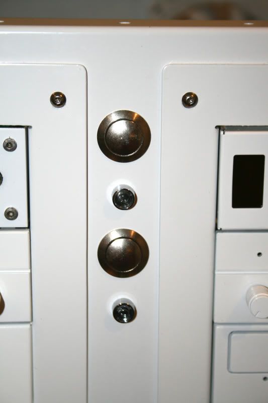
While the buttons look 'ok' they are not bling enough so I got hold of a couple of switches:
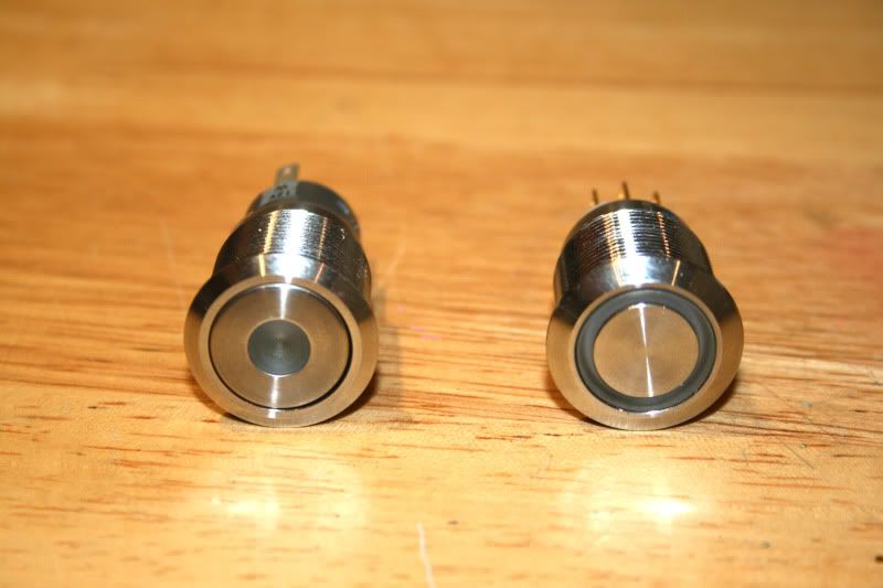
As ealrlier mentioned, the fact I am now forced to use two psu's one is a latch switch which by definition locks into place (push on - latched/ release off unlatched). This is the one on the left and will control everything bar the motherboard. It's a single white led but thanks to the opaque cover it's not too bright.
The one on the right is a momentary switch (blue ring) and will control the motherboard. The ring will be attached to the HD led header.
I tend to get quite a few emails asking how these are wired up, particulary the momentary switches which are best used fo a 'normal' pc. So here's a quick 'how-to'....
While the buttons look 'ok' they are not bling enough so I got hold of a couple of switches:
As ealrlier mentioned, the fact I am now forced to use two psu's one is a latch switch which by definition locks into place (push on - latched/ release off unlatched). This is the one on the left and will control everything bar the motherboard. It's a single white led but thanks to the opaque cover it's not too bright.
The one on the right is a momentary switch (blue ring) and will control the motherboard. The ring will be attached to the HD led header.
I tend to get quite a few emails asking how these are wired up, particulary the momentary switches which are best used fo a 'normal' pc. So here's a quick 'how-to'....
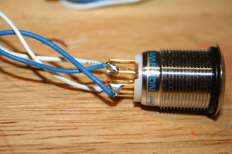
Heres a shot of the latch (left) and momentary right. I'll do a quick guide on the momentary as they are the most common used:
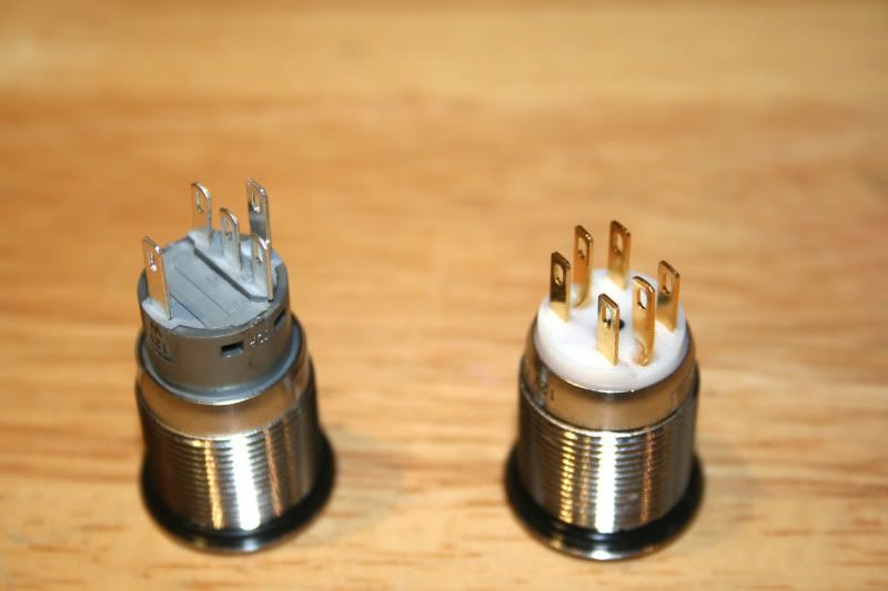
These are the 'spade' type and in all honesty the screw type are much easier to install so if you can get those do so, especially if like me you are not good with a soldering iron!
You could use spade connectors for the ones I have tbh and it would be easier but I didn't have any spare at the time so I decided to solder mine.
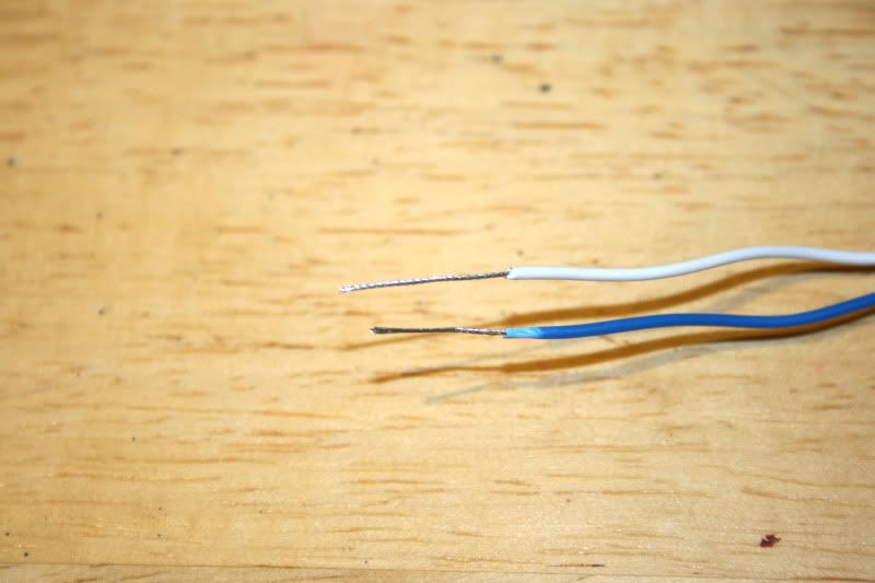
First sort your wires out. Twisting the ends makes for a neat and tidy job:
Then connect the LED wires to the + and - connectors (middle):
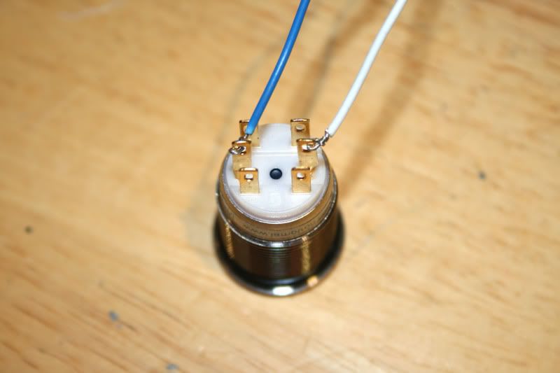
If your LEDs dont work then switch the motherboard headers around. Don't worry, you wont do damage if they are the wrong way around. Also note that the leds are rated for 3.4v but motherboard headers give out 3.3v. This is within the threshold so no bad things will happen
 . The led's will be very slightly dimmer thats all. I wouldn't advise wiring up the leds to anything other than the rated spec though as you will most likely burn out the LED.
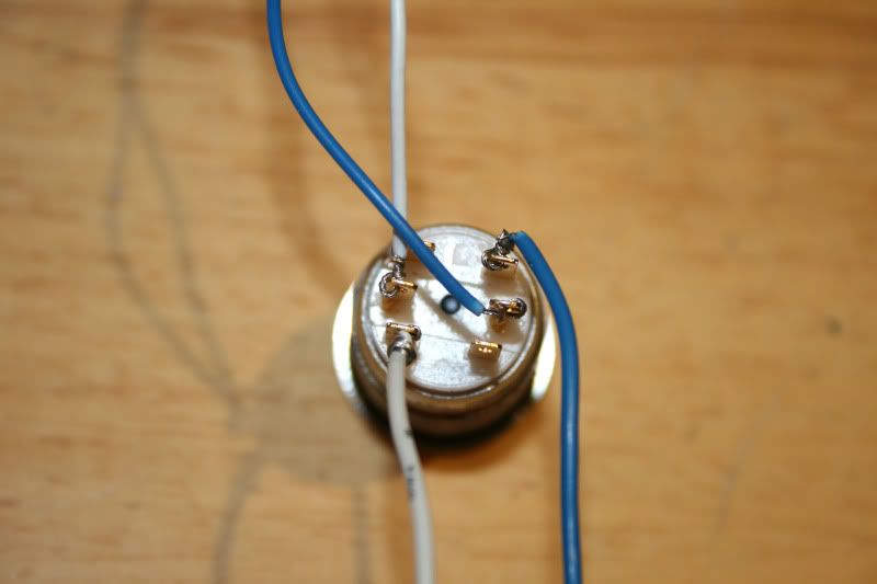
Then connect your motherboard header (in this case power + and - but the same goes for a reset switch) to tabs 3 & 4.
Heres a diagram:
Here they are wired:
Then all that is left is to solder the wires to neaten things up and to prevent a short:
Then braid the cables to complete the job:
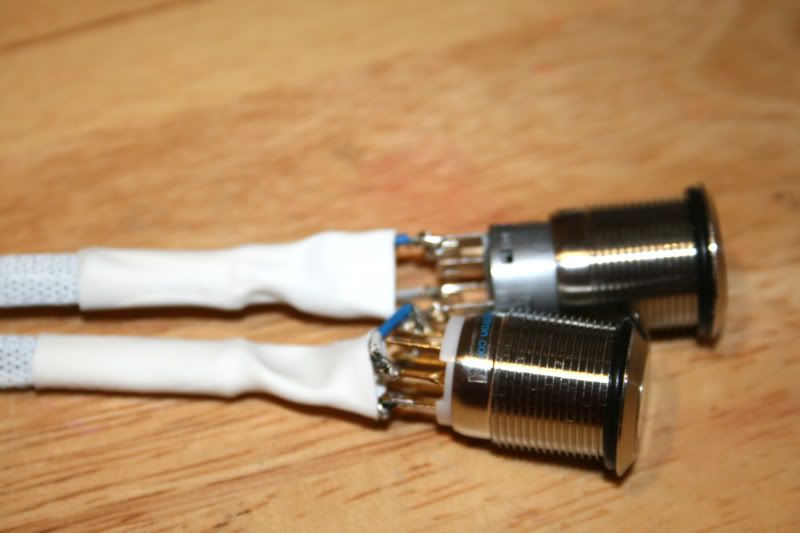
I left the blades exposed as I 'may' wish to solder other wires to the swiches to control other sections (lights etc) so not quite finished with those yet
 .
.
Hope this helps somewhat.
These are the 'spade' type and in all honesty the screw type are much easier to install so if you can get those do so, especially if like me you are not good with a soldering iron!
You could use spade connectors for the ones I have tbh and it would be easier but I didn't have any spare at the time so I decided to solder mine.
First sort your wires out. Twisting the ends makes for a neat and tidy job:
Then connect the LED wires to the + and - connectors (middle):
If your LEDs dont work then switch the motherboard headers around. Don't worry, you wont do damage if they are the wrong way around. Also note that the leds are rated for 3.4v but motherboard headers give out 3.3v. This is within the threshold so no bad things will happen
Then connect your motherboard header (in this case power + and - but the same goes for a reset switch) to tabs 3 & 4.
Heres a diagram:
Here they are wired:
Then all that is left is to solder the wires to neaten things up and to prevent a short:
Then braid the cables to complete the job:
I left the blades exposed as I 'may' wish to solder other wires to the swiches to control other sections (lights etc) so not quite finished with those yet
Hope this helps somewhat.
After a little jiggery pokery (sliced my thumb, note to self - scalpels are dangerous!), I fitted the switches I wired up earlier. Here's how they look:
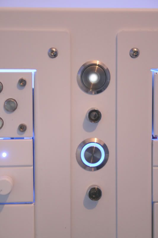
The Aquero is gonna take some configuring with this setup but it's a handy device which will hopefully keep an eye on things for me
 .
.
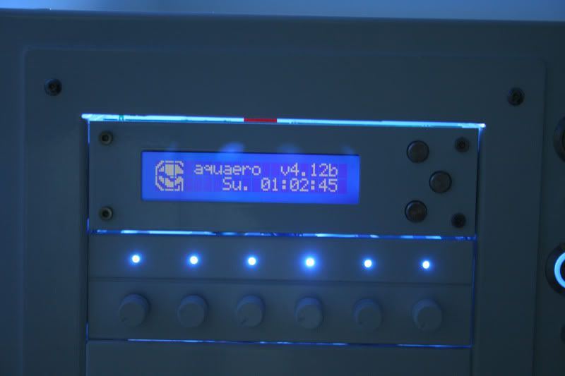
Along with the aquero I got a Matrix Orbital GX Typhoon:
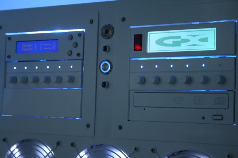
The typhoons screen colour can be configured to display the same colour as the aquero but thats something I'll have to sort out once the OS and software is installed. Look forward to playing with those two goodies
 .
.
The Aquero is gonna take some configuring with this setup but it's a handy device which will hopefully keep an eye on things for me
Along with the aquero I got a Matrix Orbital GX Typhoon:
The typhoons screen colour can be configured to display the same colour as the aquero but thats something I'll have to sort out once the OS and software is installed. Look forward to playing with those two goodies
Well I've finally come to the part I was dreading - cable tidy!
To give you an idea of what I am up against here's a basic list of cables I have to tidy:
2xPSU's (4 molex cables, 2 SATA cables, 2x 24pin ATX, 2x 8pin CPU, 4xPCIe 8pin, 4xPCIe 6pin).
5x SATA data cables
2x Pumps (+2x sensor cables + 2x LED cables)
16x fans
Fan controllers x2
GX Typhoon + aquero + sensor cables
Motherboard headers
4x Cold Cathodes
...all to be hidden in a case with 3 windows and not alot to hide them behind!
So i did a quick mock up and found that no matter what I did, in whatever orientation, the thing looked liked a rats nest! My last hope was to use the thick motherboard tray support bracket.
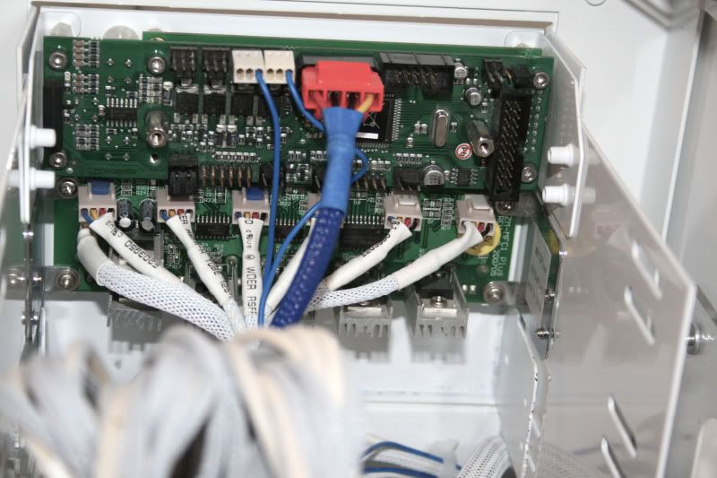
I made a few extension cables so most of the wires can be hidden behind the bracket as well as cutting down the amount of excess wiring inside the case. Here's a shot of the zalman fan controller and above it the aquero with barely anything attached!!!
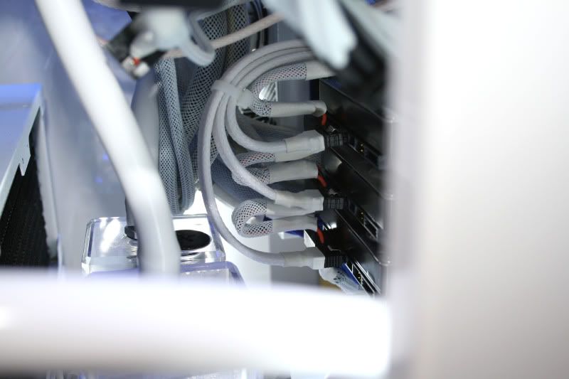
One problem that I found with braiding the SATA cables was that it made them much stiffer and more difficult to bend/route in a neat manner due to the decrease in flexibility. However, I persevered and managed to get the HD rack (2x1TB raid 0, 1x2tb, 1xSSD, 1xDVD) looking reasonable:
Fitting the bracket while everything was in place was an absolute PITA. I had to drain the loops, remove all cabling then adjust it slightly from it's correct mounting position as I wanted the bracket to cover the modular fittings of the PSUs to make the whole thing look as neat and tidy as possible:
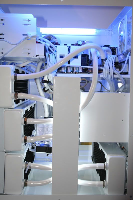
It's getting there now! Still a bit more tidying to do (the above shot is the 'messy' end but certainly starting to take shape
.
To give you an idea of what I am up against here's a basic list of cables I have to tidy:
2xPSU's (4 molex cables, 2 SATA cables, 2x 24pin ATX, 2x 8pin CPU, 4xPCIe 8pin, 4xPCIe 6pin).
5x SATA data cables
2x Pumps (+2x sensor cables + 2x LED cables)
16x fans
Fan controllers x2
GX Typhoon + aquero + sensor cables
Motherboard headers
4x Cold Cathodes
...all to be hidden in a case with 3 windows and not alot to hide them behind!
So i did a quick mock up and found that no matter what I did, in whatever orientation, the thing looked liked a rats nest! My last hope was to use the thick motherboard tray support bracket.
I made a few extension cables so most of the wires can be hidden behind the bracket as well as cutting down the amount of excess wiring inside the case. Here's a shot of the zalman fan controller and above it the aquero with barely anything attached!!!
One problem that I found with braiding the SATA cables was that it made them much stiffer and more difficult to bend/route in a neat manner due to the decrease in flexibility. However, I persevered and managed to get the HD rack (2x1TB raid 0, 1x2tb, 1xSSD, 1xDVD) looking reasonable:
Fitting the bracket while everything was in place was an absolute PITA. I had to drain the loops, remove all cabling then adjust it slightly from it's correct mounting position as I wanted the bracket to cover the modular fittings of the PSUs to make the whole thing look as neat and tidy as possible:
It's getting there now! Still a bit more tidying to do (the above shot is the 'messy' end but certainly starting to take shape
The reason why I didn't originally want to fit the brack was because of the window engraving as it tends to 'bleach' it out being opaque on white:
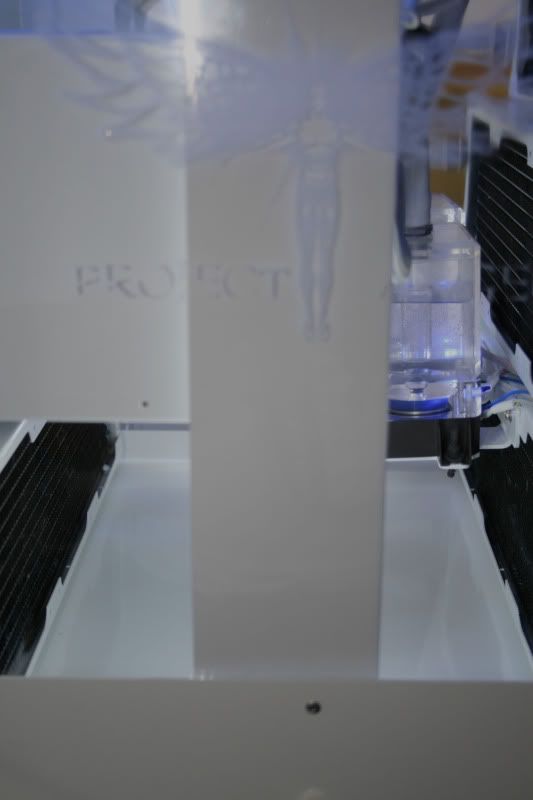
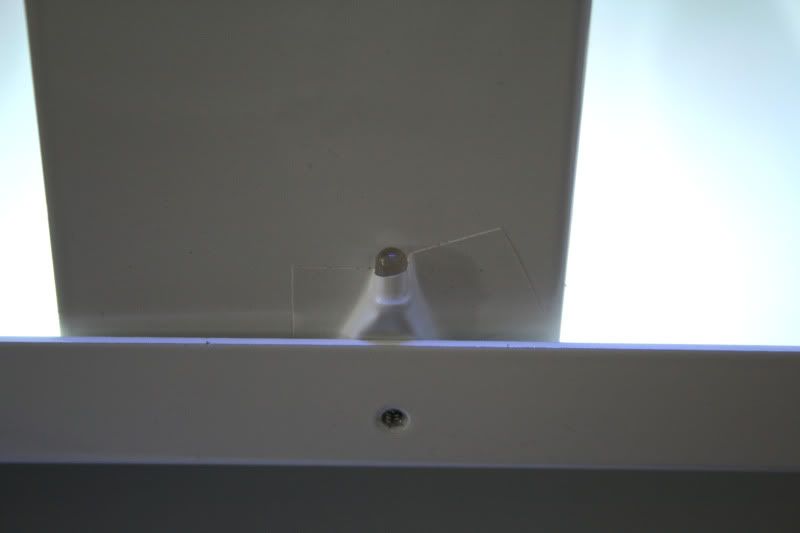
So my next task was to make the Angel engraving stand out a little more without making it look like some cheap sticker. I opted for placing an LED under the edge of the perspex which would hopefully refract the blught light on the engraving. The LED was not directional so I blanked out the side of the led with some good old insulation tape as I just wanted the beam to point upwards toward the perspex of the side panel:
With the side panel on (white cathodes off):
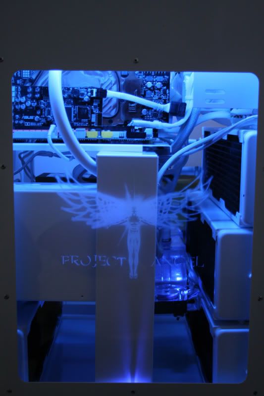
With the side panel on (white cathodes on):
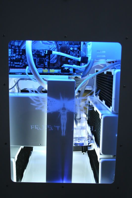
Worked out quite well. It's a shame the photos really don't capture the full glowing effect of the Angel.
So my next task was to make the Angel engraving stand out a little more without making it look like some cheap sticker. I opted for placing an LED under the edge of the perspex which would hopefully refract the blught light on the engraving. The LED was not directional so I blanked out the side of the led with some good old insulation tape as I just wanted the beam to point upwards toward the perspex of the side panel:
With the side panel on (white cathodes off):
With the side panel on (white cathodes on):
Worked out quite well. It's a shame the photos really don't capture the full glowing effect of the Angel.

1.7gb, jesus man wtf format is that? Even my 15min vids are under 800mb
Gratz dude! Now you can relaxCan't wait to see the vid man, have loved watching this build come together.
Cheers m8. It's been a long journey and a rollercoaster year but finally got it all together now (life & PC!)
1.7gb, jesus man wtf format is that? Even my 15min vids are under 800mb
Tried numerous, PAL DivX being the one which compressed it down to 150mb but quality was pixelated crap. Settled for HD1080p using DivX. Did it all on the laptop so the vid aint the best quality anyway so made the best I could using the tools I had (Angel is priming atm
nice work matey
great to see this finished .... sooo what next
Dunno m8. I might do a TJ07 build, or maybe I'll spoon my eyes out with a poop scoop - either way the effect is the same lol (imo). Tbh I'm liking the new Lian-Li V2120 so might bag one of those. Gonna enjoy what I have for the minute though and get back into 'geeking' as I've been out of the loop for too long - keeping my options open I guess
Just use windows movie maker and encode to wmp, its all I ever use. Even my 1080p stuff done in sony vegas at 8MB/s never his a gb

Nice vid dude, no wonder its huge, theres loads of images. Bet that took a while to edit!
delusion77
New member
intense pc, its massive!
Nice vid dude, no wonder its huge, theres loads of images. Bet that took a while to edit!
Yeah. Tbh the rendering is a bit fubar as the video and pictures were taken at a different res resulting in slightly 'squashed' images. I did a normal res HD one too but that looked worse with dirty great black borders lol. Tried numerous codecs but aac (mp4) resulted in the best knocking the vid down to just 94 mb! Amazingly the quality was best on this one too!
Hopefully MM and enermax will be happy with it!