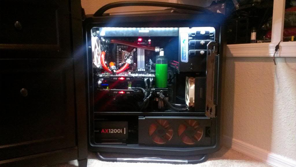
The cooling loop is complete!
[BEGIN TRANSMISSION]
Hello again everybody! I know it has been quite sometime since my last post and I said it would only be two to three days or so. Well, naturally, I ran into complications along the way in the course of building my watercooling loop. I found that I couldn't build the loop according to my original design so I had to change things and ended up with some parts missing so I ordered those and made more changes and ordered some more things and so on. My apologies for taking so long people. In my own defense this is my
first attempt at a true watercooling build so please go easy on me! With that said I'll try to lay out the process from beginning to end so bear with me.
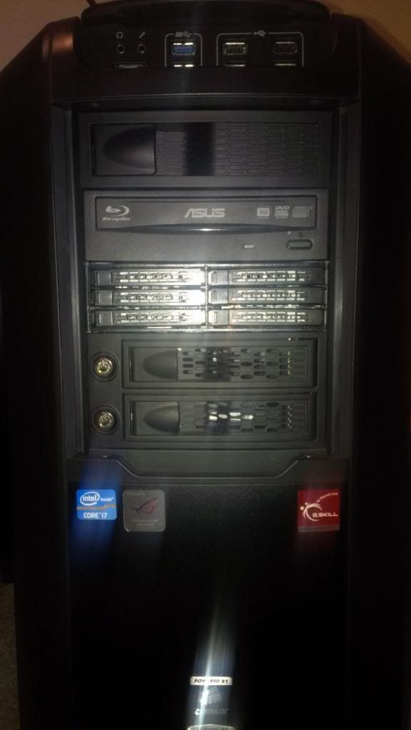
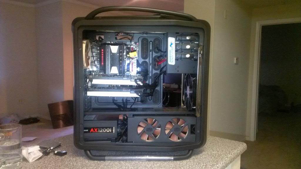
One last look at Paradox in an aircooled configuration
and my horrendous cable management.
So let's begin the process then. First I want to remind everybody that I have been intending to do this for a long time now (hence the reason I chose the Cosmos II in the first place) and that this is my first effort so many of you may find things wrong with my work and be tempted to suggest better ways of doing things (which I welcome but please keep it civil). With that said I will acknowledge that some things did not turn out that way I would have wanted.
OK now let's talk design. I wanted to use the full potential of the Cosmos II case so the first consideration was to plant a radiator in every place that I possibly can (which there are three). Secondly, I thought about the flow path of the loop. It took a lot of research and asking questions to get this right. I have opted for a completely serial loop that is as short as possible. Here is the complete list of components used:
Pump: Swiftech MCP655 PWM with Bitspower modkit and pump top
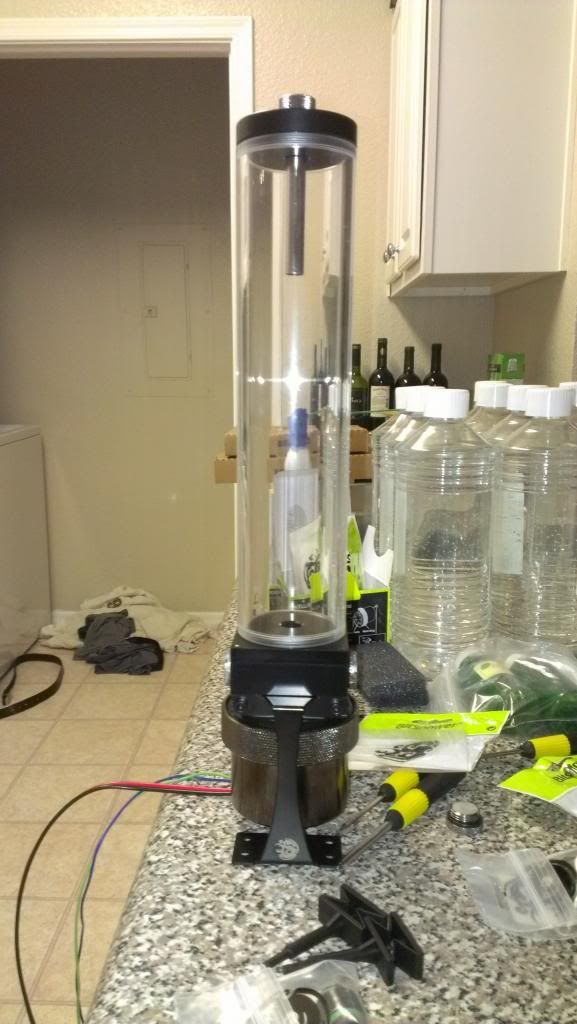
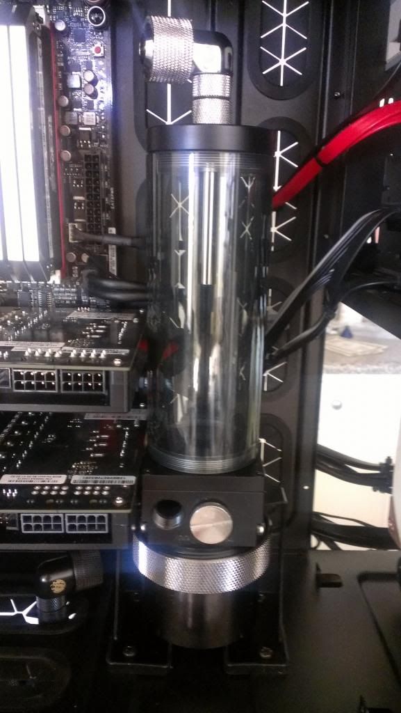
Reservoir: Bitspower 150mm with pumptop attachment
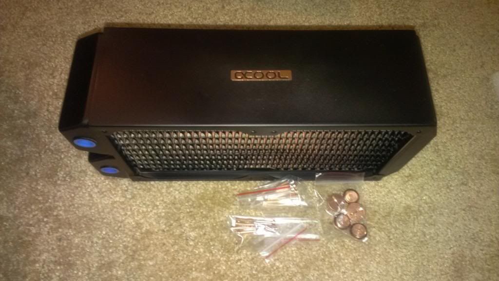
Radiators: Alphacool NexXxos XT45 360 (top), UT60 140 (front), Monsta 240 (bottom)
Coolant: Alphacool laboratory grade water with Swiftech HydrX anit-corrosion/anti-microbial additive
Fittings: All Bitspower compression fittings and various adapters
Tubing: Primochill Primoflex Advanced LRT black and red tubing 1/2" ID 3/4" OD
CPU Block: EK Supremacy full nickel
VRM Block: EK nickel acetal
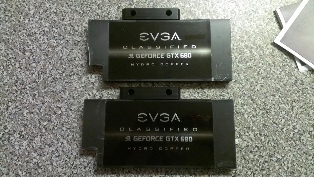
GPU blocks: EVGA Hydro Copper
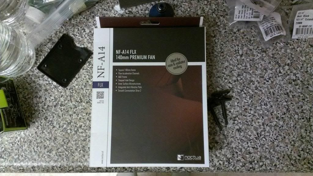
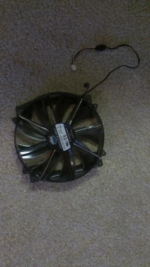
Fans: Noctua NF-F12 x7, NF-A14 FLX x2
Extras:
- Bitspower inline temperature sensors
- Bitfenix Alchemy 600mm white LED light strip
- Corsair Dominator Platinum 4x4GB 2400 MHz
- Samsung 840 Pro 128GB SSD
- Koolance VL3N quick disconnect fitting
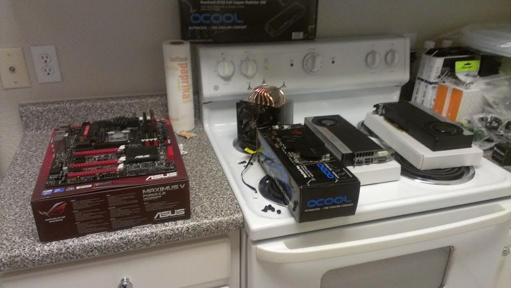
Now on to the teardown:
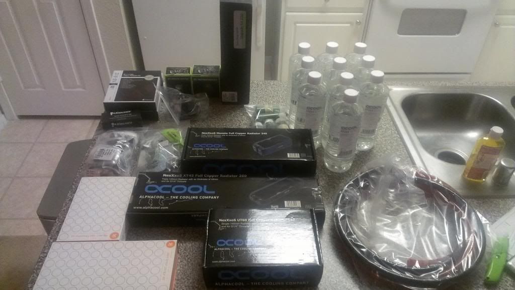
All participants are prepped and ready for surgery.
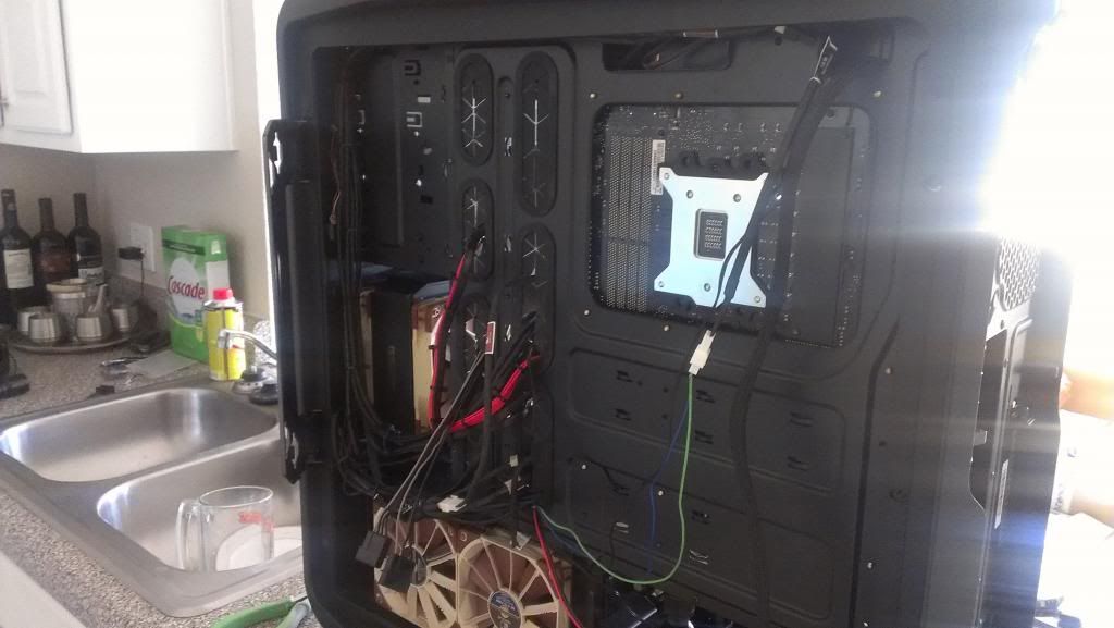
I had to do all of this in my kitchen because I don't have any other horizontal space to work with and also that was the only place in my home that is not carpeted. I didn't cook much during this time obviously. Ah, such is the challenge of living in an apartment...
Here is the pump and res. Mounting this was a bit of a challenge because the bottom of the motherboard area is not flat so I was forced to mount it extra close to the graphics cards. Ideally it should be placed right in the middle between the graphics cards and the 5.25" area. I might in the future put a plate on the bottom to facilitate that. The flow path will start from here and go the the front rad...
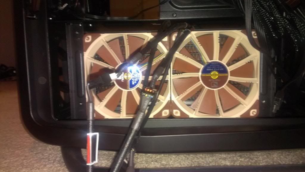
The stock 200mm fan comes out to mount the 140 rad.
Using both NF-A14 FLX fans in push-pull here. The input will be the output of the pump and will flow out to the bottom rad...
The output of the front rad flows into the top port and comes out of the bottom. The grommet holes line up perfectly so the lines are vertical. I used a 90 degree compression fitting, then a 50mm extension, then a 90 degree adapter.
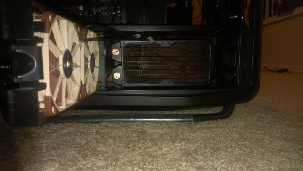
Here is the bottom radiator. This is a 80mm rad so push-pull is a must. The fans pushing air in are mounted on the door and not the rad to help bring fresh air in.
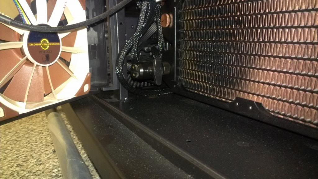
You will notice the output of the bottom rad goes to a 20mm extension then a five-port adapter. I used the five-port to place the first of the two inline temperature sensors. This allows me to monitor the temperature of the water before it enters the heat-producing components. This also presents a challenge in connecting my PSU cables as you will see later on.
I sure do love these Alphacool rads! Those multiple ports allow for some interesting possibilities. This is my solution for draining the loop. A simple valve with a plug on the end. I just unscrew the plug, attach a line, open the valve and out it goes. Its at the lowest point in the system too.
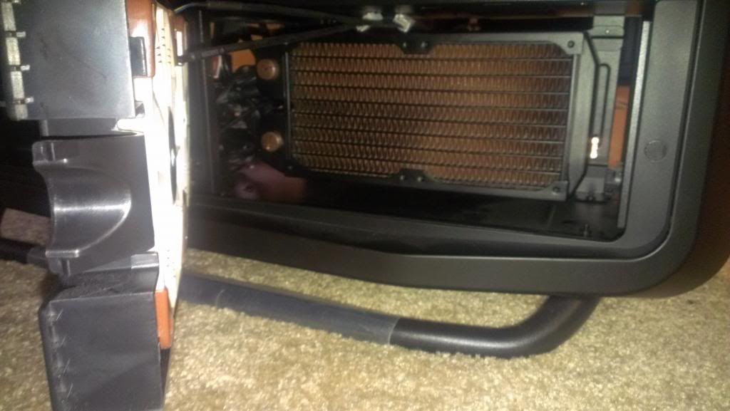
This presents a better representation of the flow to and from the bottom rad and into the graphics cards.
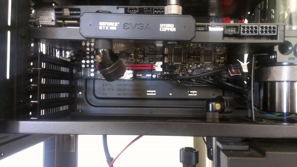
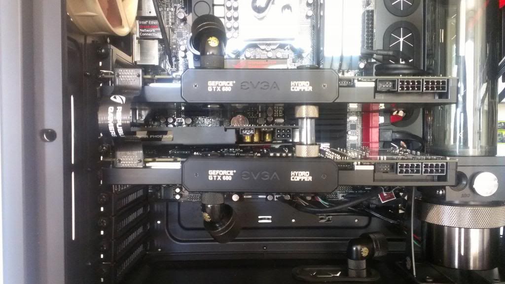
Here is the flow path thru the graphics cards. This is where the question of serial vs parallel flow came to a head. I decided on serial configuration thanks in no small part to the information in this forum and others like it. I used a Bitspower Crystal Link tube to connect the graphics card waterblocks. The EVGA logos light up red when powered on.

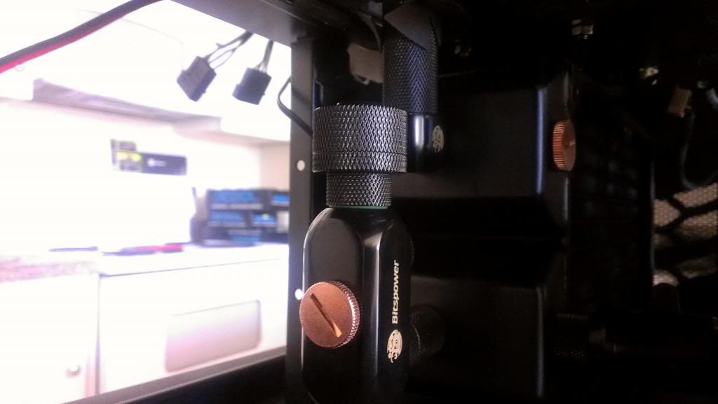
Here is where things get interesting. I used a 45 degree fitting to connect the output of the graphics cards to the lower part of the VRM block to ensure a short run of tubing. Then to connect the top part of the VRM block to the CPU block I used 90 degree fittings to connect those. I'd originally planned on using another Crystal Link tube for this part but the blocks were not level (off by 5mm or so) so I ended up having to settle for normal tubing and fittings. The rear exhaust fan has been reconfigured to supply air so the top rad gets cooler air. The above shot also shows my newly-acquired Dominator Platinums in all their glory. More on that later.
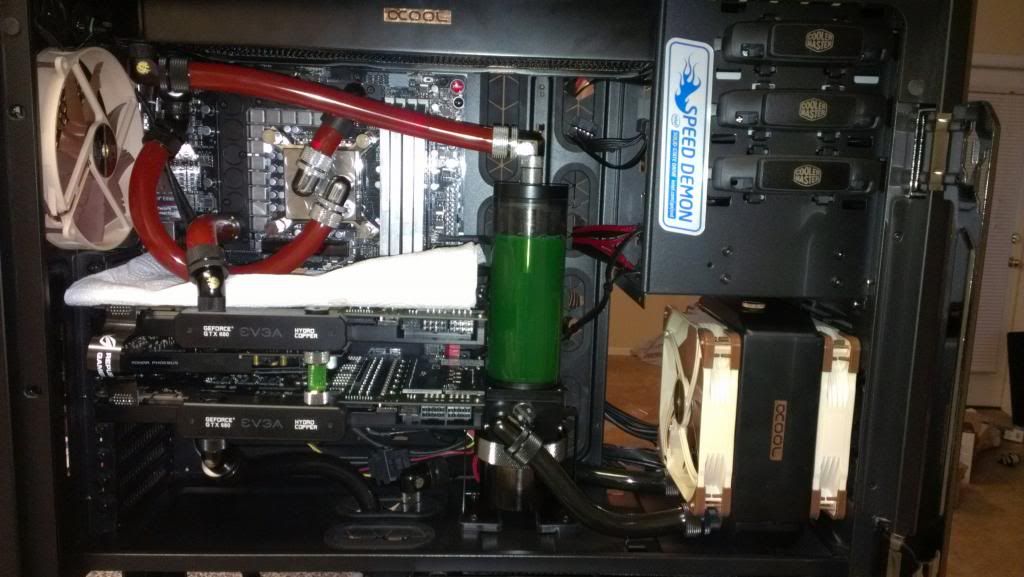
This picture is meant to show the flow path out of the CPU block and into the top rad. I originally meant to use an extension to come straight up from the CPU with the 90 degree fitting on top. I made the decision to do it this way for now because the extension I received ended up having two female ends instead of male/female and I didn't feel like waiting to exchange it. This is one of the two parts of the build that is not to my liking; the other part being that the coolant wound up being green and really mucking up the color scheme. I was more concerned with the properties of the additive at the time of purchase. Something I will definitely change next time round. Moving on to that flow path to the top rad...
It's quite busy up here. There is a 45 degree fitting where the output of the CPU block enters, a t-line adapter and a male-to-male adapter. That t-line adapter is where my second temperature sensor is connected, allowing me to determine the heat added to the loop before it gets cooled. You can't see it in this picture but there is also a second line that goes out to the back of the case to a Koolance VL3N quick disconnect fitting that I will use to help vent the loop during the draining process. This little part is made possible, again, by the multiple ports on these Alphacool rads. I initially tried to fill the loop this way but found it way easier to fill it directly into the res.
A better look at that vent. Outta sight, outta mind.
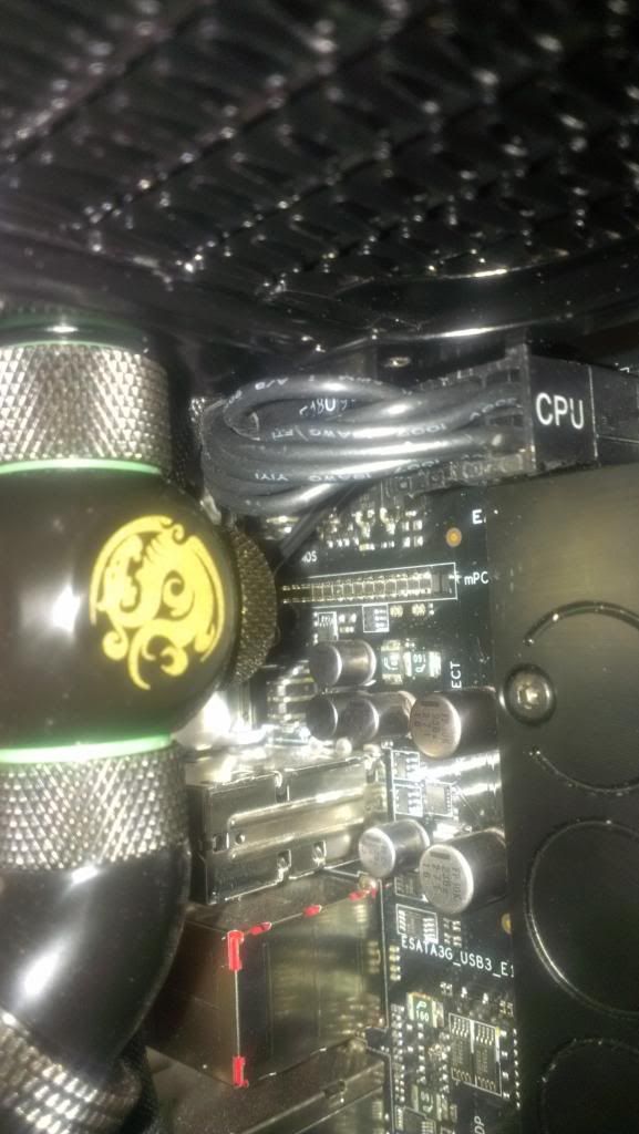
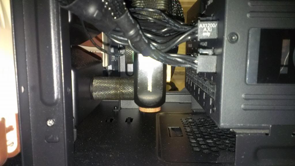
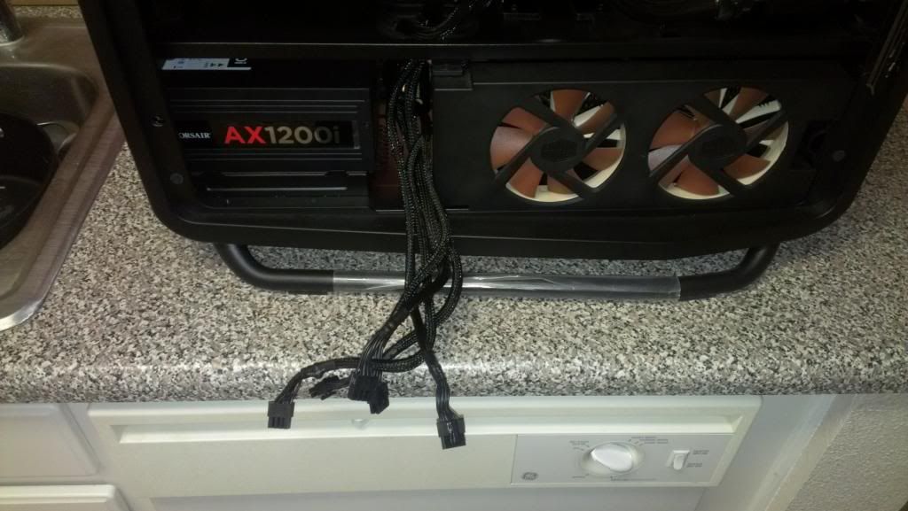
Lets talk about that 8-pin CPU power connector. Getting that connected was a *****! The Cosmos II does not allow for very thick radiators to be mounted on the top. And I managed to get a 45mm thick one up there. The spacing between that and and VRM block made it literally impossible to connect it with doing some cruel and unusual things to the connector. I had to shave the clip and other protrusions from the connector in order to get it to fit. Even then it barely fit. It is that tight.
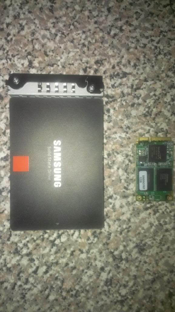
Also note that this is the same area where the mPCIE combo card connects to the motherboard (for those reading this log for the first time, the mobo is a Maximus V Formula). There is no longer enough space to connect that card, which presented a huge problem for me. I had an mSATA SSD connected to it which I used to boot Windows from, meaning I had to get a new SSD...
My new SSD is none other than the Samsung 840 Pro. I also took the opportunity to up the capacity to 128GB vice 60GB as I found myself in need of more. It's faster by leaps and bounds, naturally; the combo card is hard wired to a SATA II (not SATA III) port on the chipset anyway.
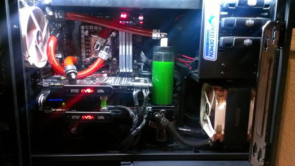
Here is a good look at everything powered on and running. Finally, the last part of the flow path from the top rad back to the res by means of 90 degree fitttings. The res is part of the flow path of the loop and where the loop is filled from. I chose this type of res because 1) bay-mounted reservoirs are known to not be very reliable, 2) it works better in removing air bubbles from the loop and 3) the vertically mounted res is better at providing suction for the pump via gravity. Take note of my placement of tubing; black on the bottom, red on the top. Interior lighting is provided by a Bitfenix Alchemy LED light strip. But damn, that antifreeze...
I haven't forgotten about the memory. At times I found myself using almost all 8 gigs of memory in my outgoing configuration (which was 2x4GB G.Skill Trident X 2400 Mhz CL10 BTW). I chose Platinum in particular because they are just badass and I couldn't resist. 4x4GB, 2400 MHz, 9-11-11-31. Pretty serious stuff. Unlike the Trident X, this stuff actually clocks to its rated XMP specs out of the box, no tweaking required. So now that the loop has been covered in its entirety we can move on to that wiring.
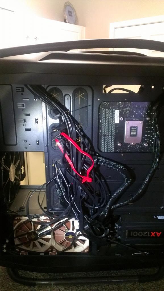
I have yet to
completely tidy up the cables but have made some progress. All of the front panel wiring is bundled up and tucked behind the edges of the case and the SATA data cables and bundled flush against one another. All fan cables on the top are tucked behind the rad and out of sight from the motherboard side.
No grommet holes directly underneath the motherboard and floor-mounted grommet holes are occupied by watercooling tubing and PCIe power cables. I'm not ready to cut holes underneath the motherboard at this time so I am stuck with this mess of cables visible on the bottom for the time being.
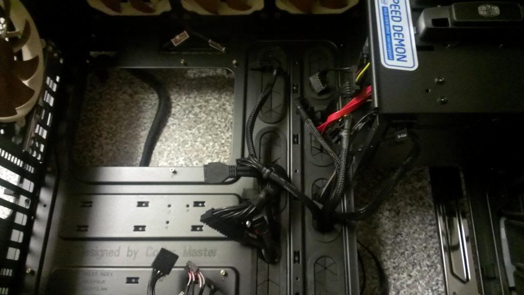
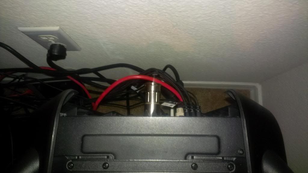
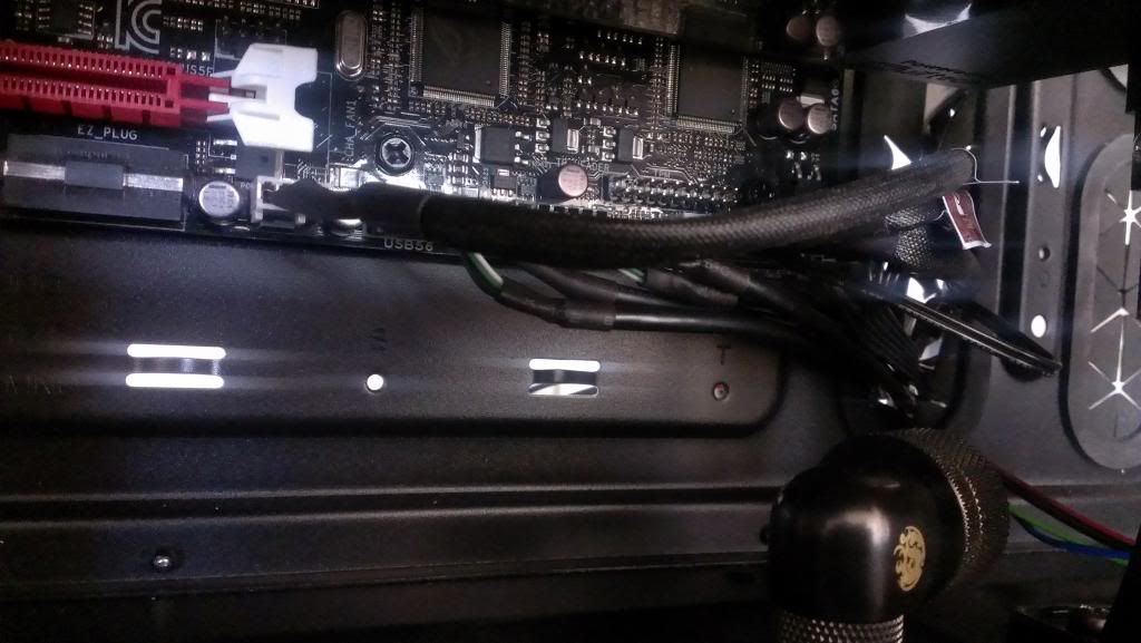
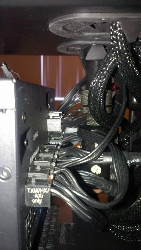
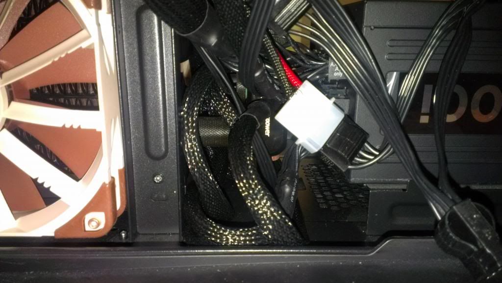
And now to connect the PSU.
The sleeved cables in the foreground go up to the graphics card and sound card thru the floor-mounted grommet holes but connect on the opposite side of the PSU and the accessory connectors for everything else connect to the side of the PSU in the foreground. And there is only 15mm or so of space between the watercooling fittings and the PSU. It took some time but I got it to work. The hard part was connecting all of the cables AND mounting the PSU to the back of the case.
CONCLUSION:
If you have made it this far then pat yourself on the back. Barring a few details I really like how this stage of the project has turned out. With that said I must report some bad news: my CPU still doesn't overclock worth a damn. Still can't get above 4.5 GHz. In fact it is getting more difficult to overclock as time goes on (crashes more; having to turn things down). Yep, the silicon is really starting to break down so I'll have to get a new one. At least now that my system is properly watercooled I have proven that fact beyond a shadow of a doubt. So until I replace the CPU I cannot share any benchmark scores as I'd originally intended.
Project Paradox in its current form is almost complete. In the next and final stage I will begin cutting my wires to length, sleeving them and getting them tidied 100%. Of course I will install a new CPU and OC and benchmark it (hopefully it will be better than this one)
Signing out
[END TRANSMISSION]
")


 Well as you can imagine I naturally tried all kinds of thing to improve the situation but in the end I resorted to acquiring a second 3770K. But wait it gets worse.


")
