AlienALX
Well-known member
I'm not going to lie this only came about yesterday. I saw a video and an idea I had had for about what? 17 years finally became viable.
So what in tarnation is a G.E.C.K? well any one who played Fallout 3 to completion will know. It is located in Vault 87 and you need it for Project Purity. It has something to do with farming and vitality of land, but more importantly it filters water from radiation etc making it safe. This is a GECK.

However, it also stands for something else. After Fallout 3 launched Bethesda released a tool for modders to make quests and items with. The Garden Of Eden Creation Kit. Very clever.
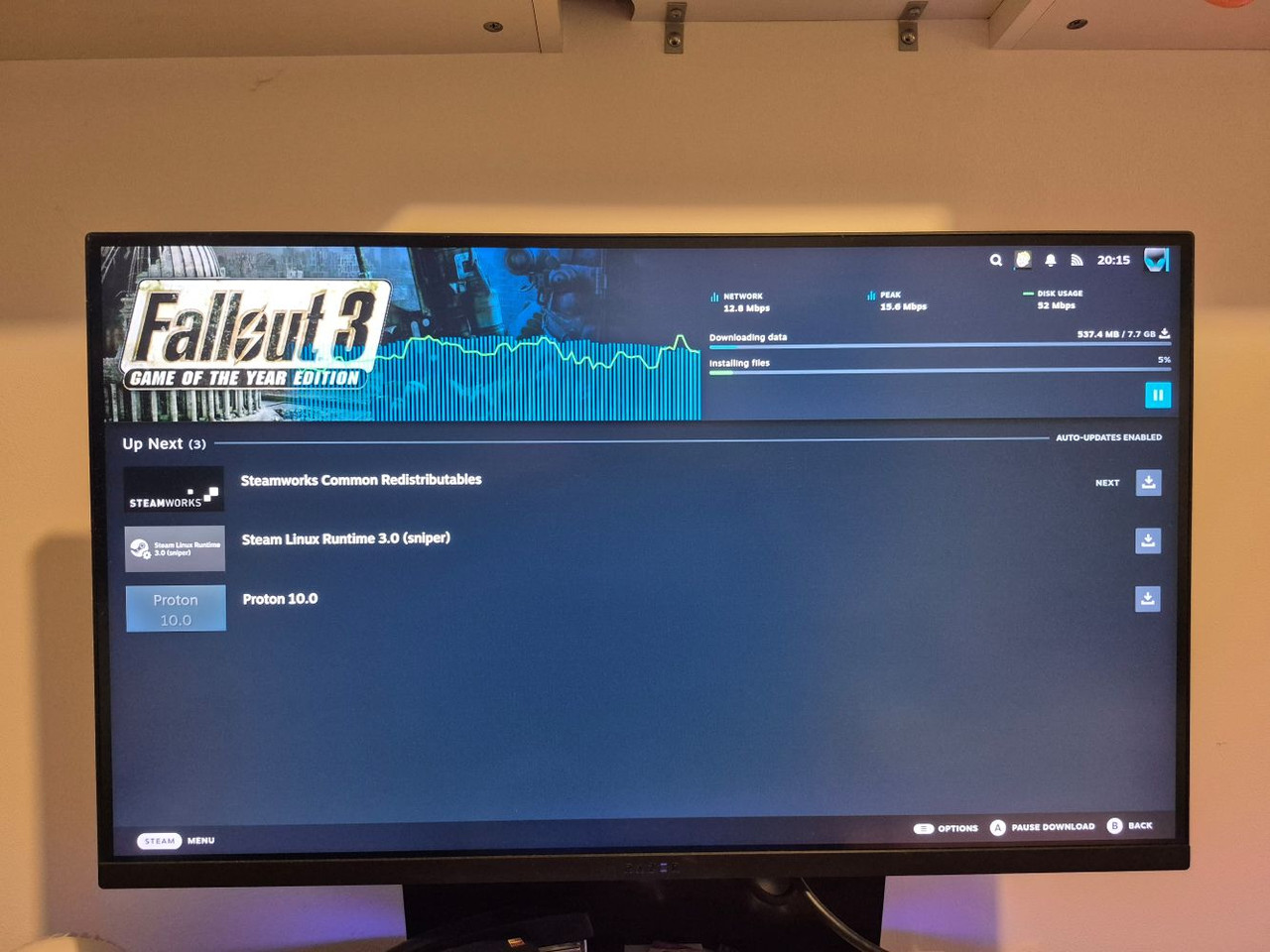
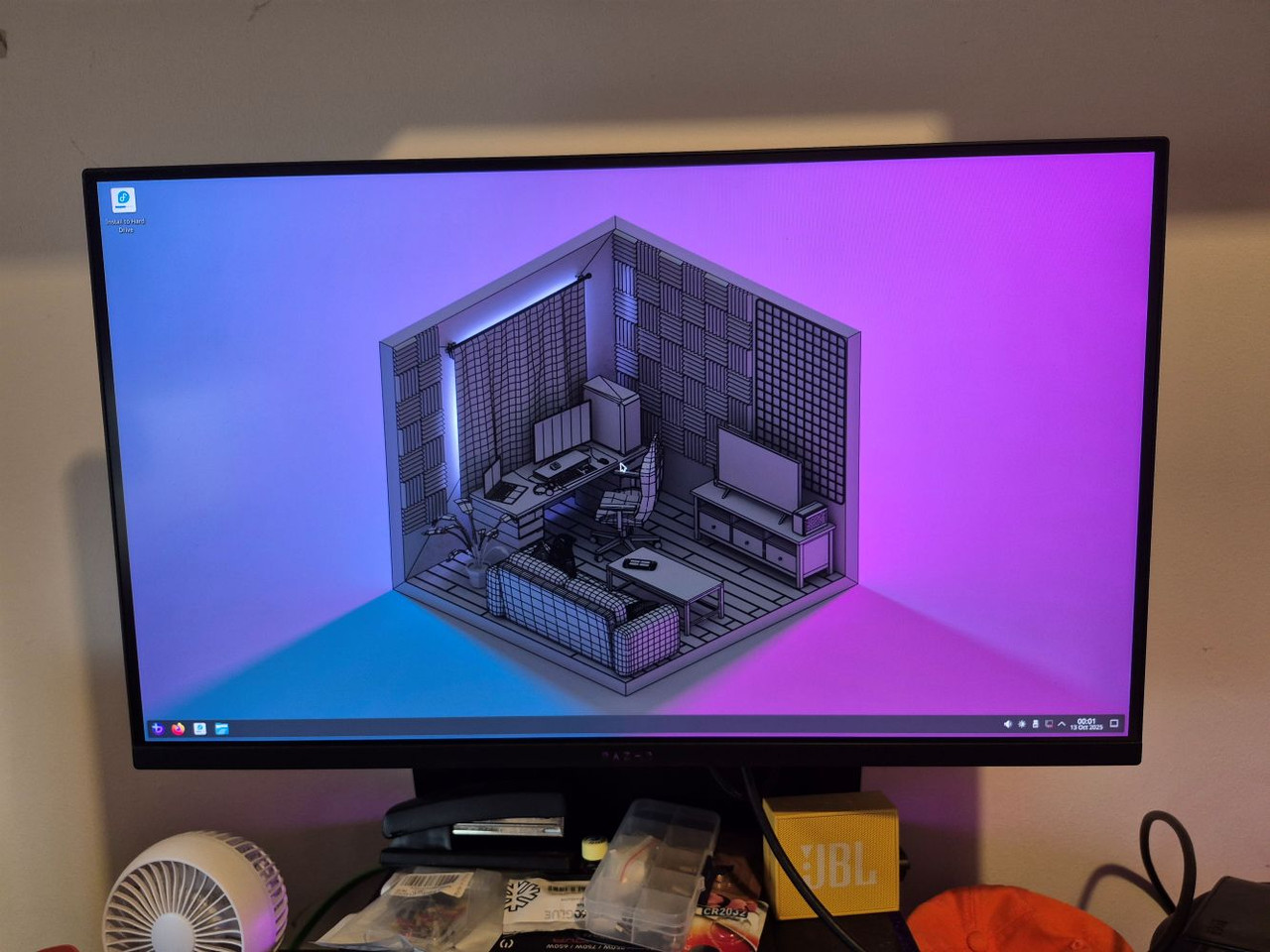
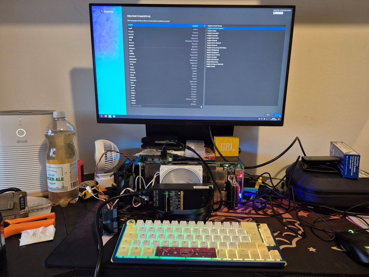
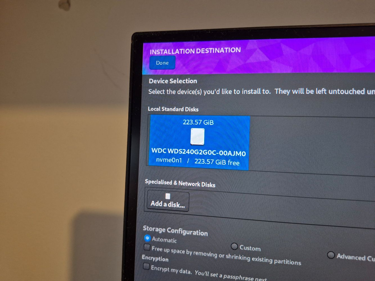
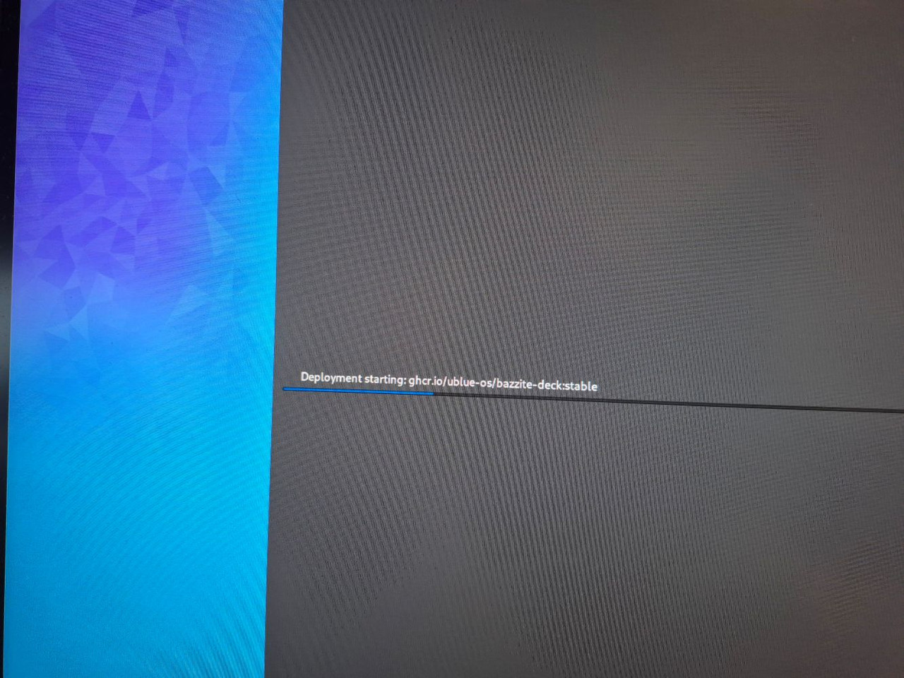
So what is my GECK for and what will it do? hilariously it will be a working computer (running Linux, it does not work with Windows **yet**) that is built solely for the playing of Fallout games.
And this is where it gets very different indeed.
So yes yesterday I was watching the tube of poo and a video popped up from Hamish, AKA Budget Builds Official. I mean no disrespect here but I don't sub to his channel because it is mostly him playing with cheap crap (literally) for lots of views. Picking the peanuts out of poo is not something I would normally partake in so yeah.
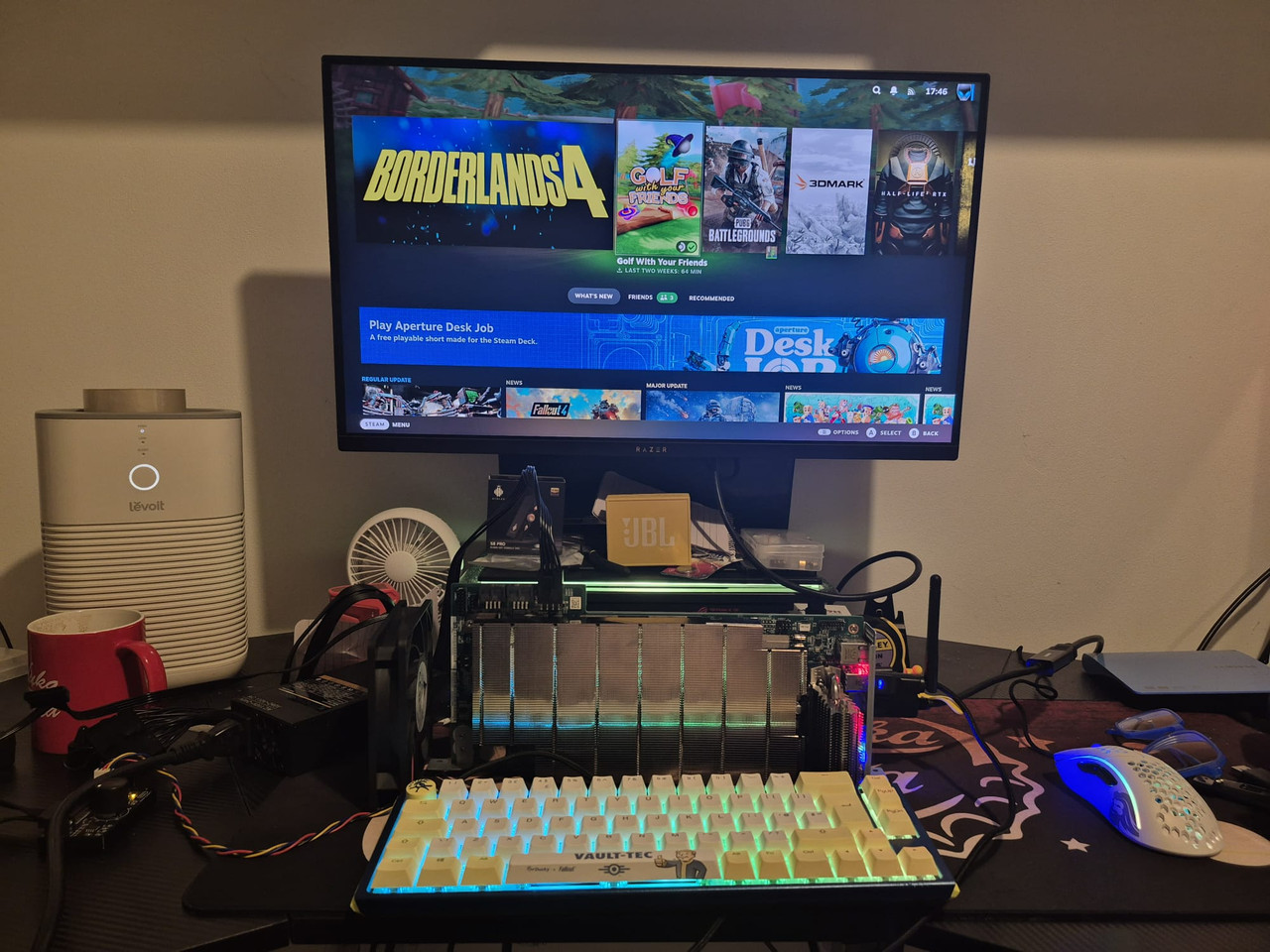
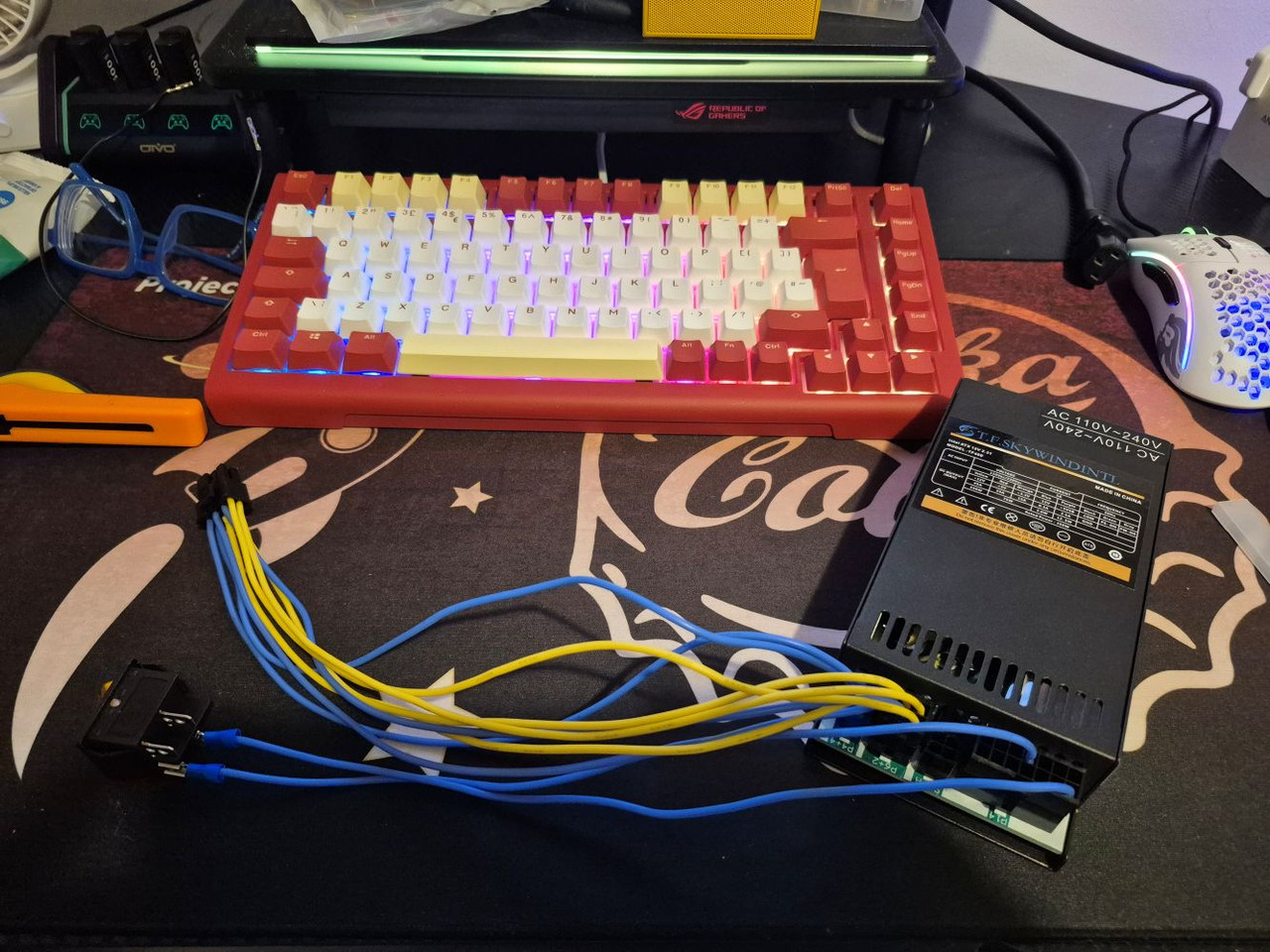
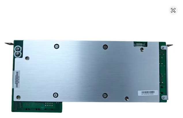
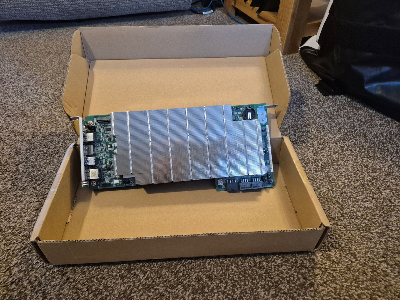
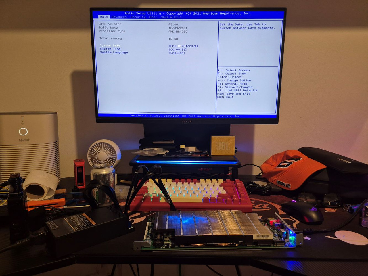
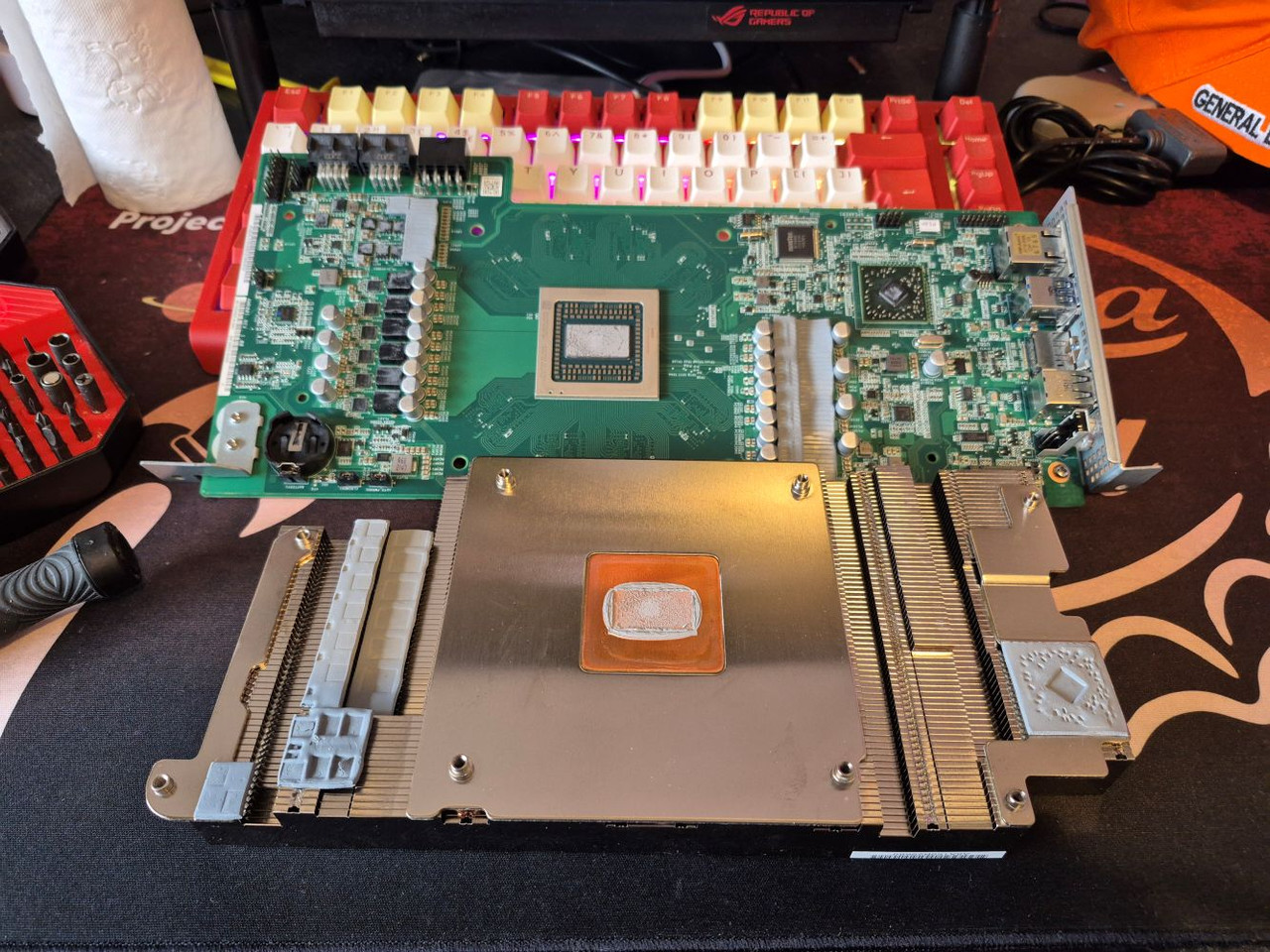
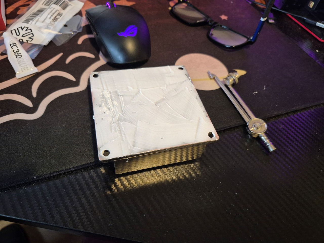
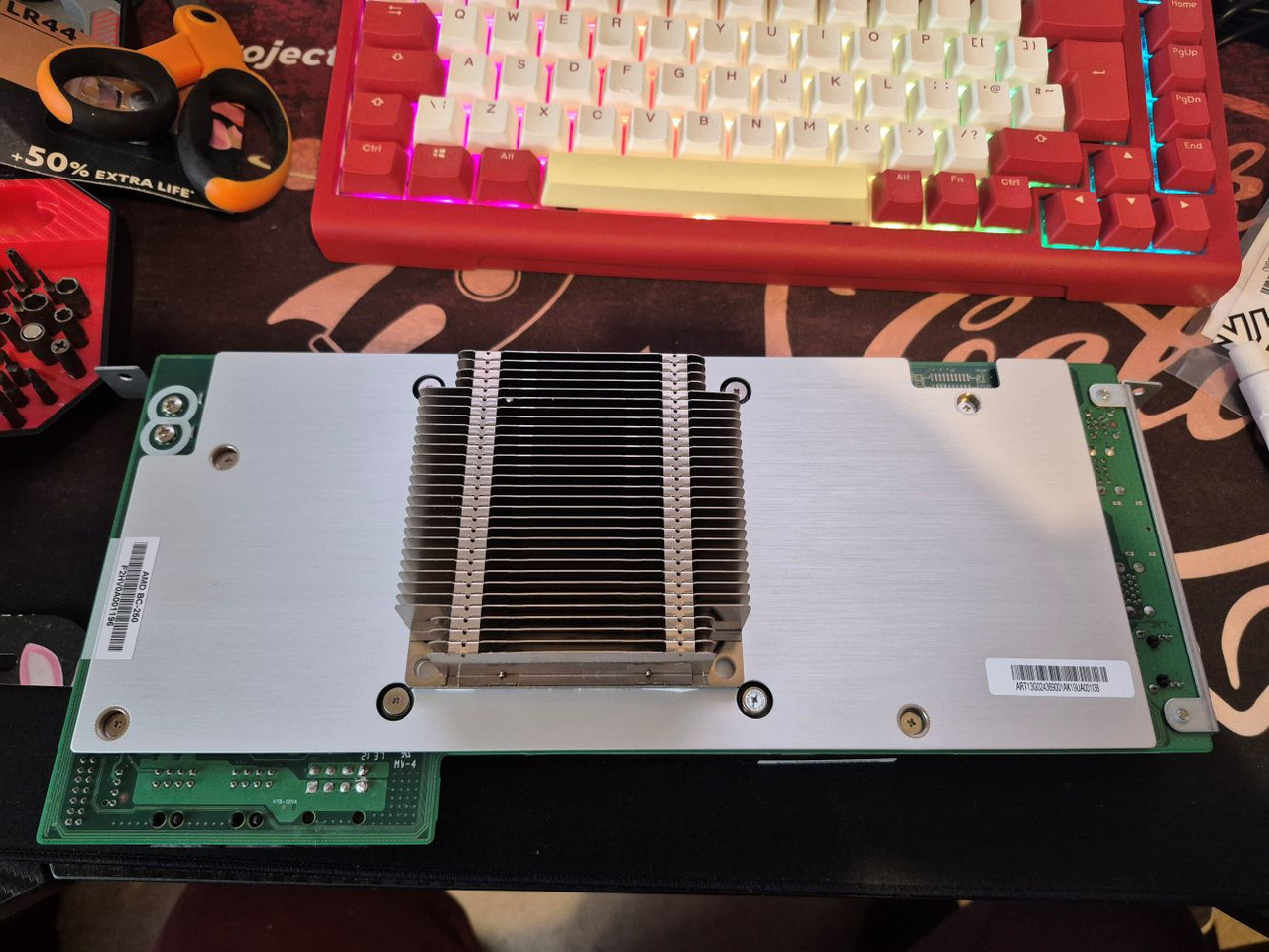
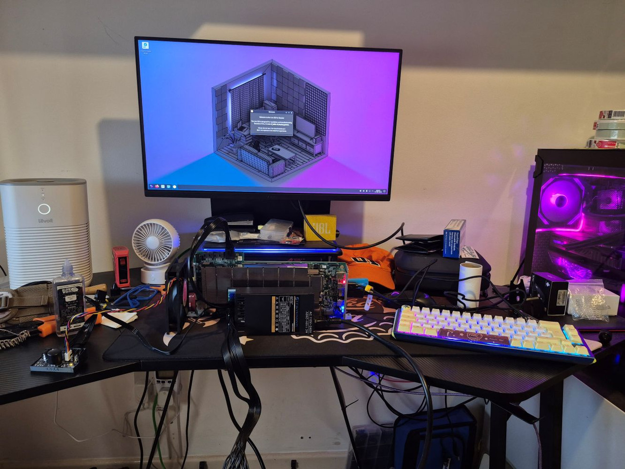
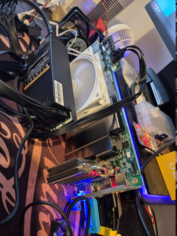
However, yesterday he posted what is, IMO, his most interesting video yet. Basically he got hold of a back plane that was built for mining that contains a Ryzen APU (most specifically the one from the PS5) as well as 16gb memory and etc. IE, a whole PC on a back plane. This.
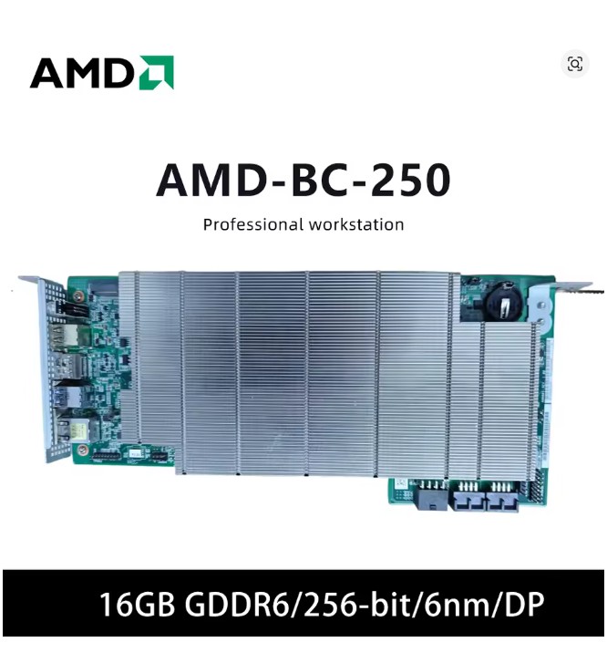
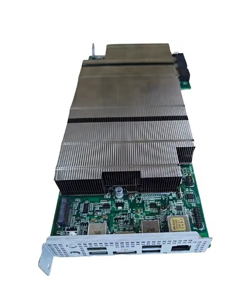
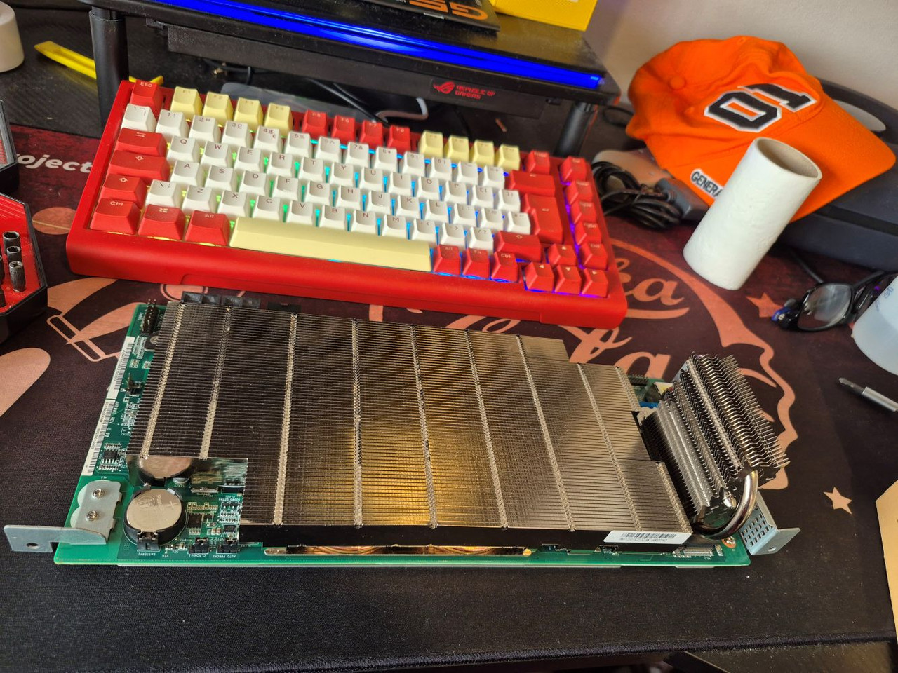
It is dual slot and about the size of a GPU. Yet, it is an entire computer on a single board. Couple more pics.
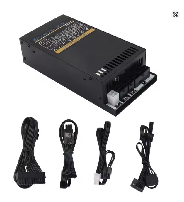
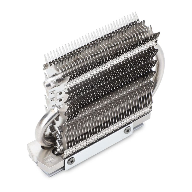
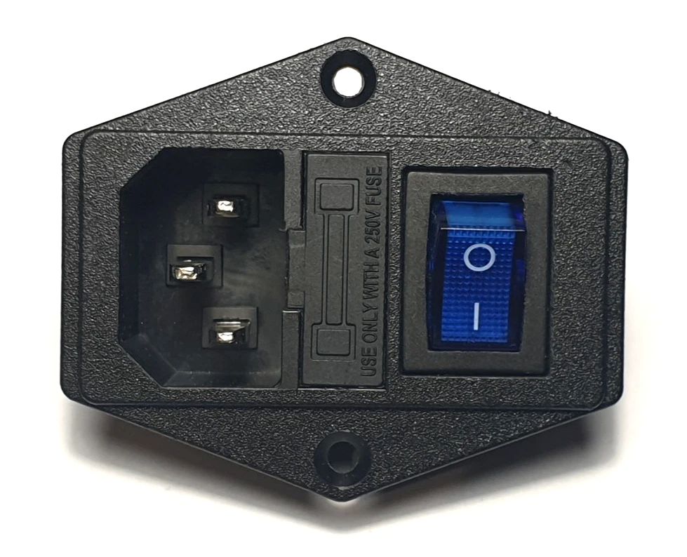
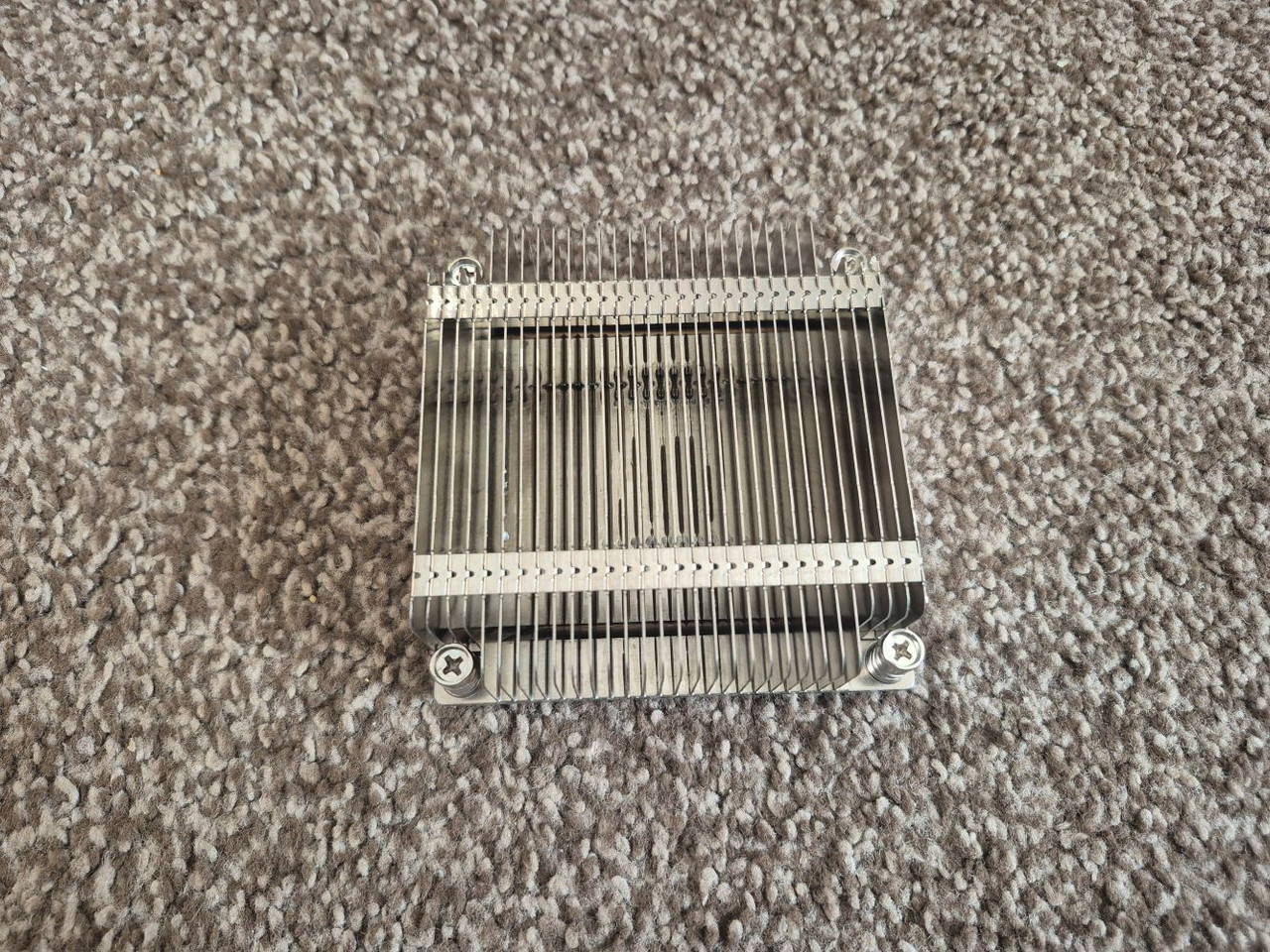
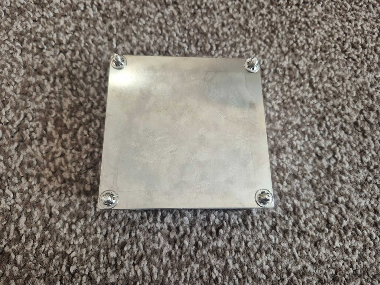
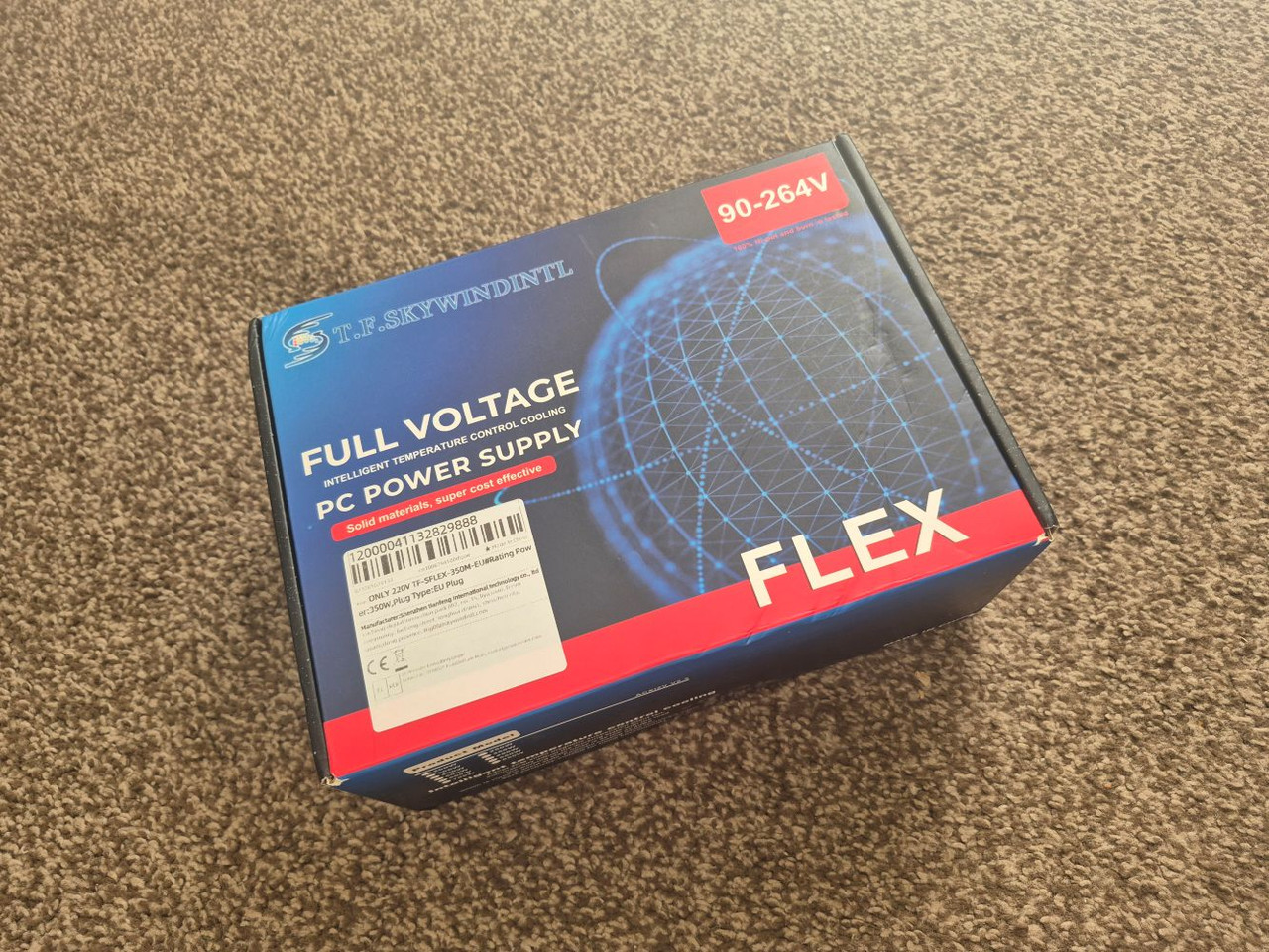
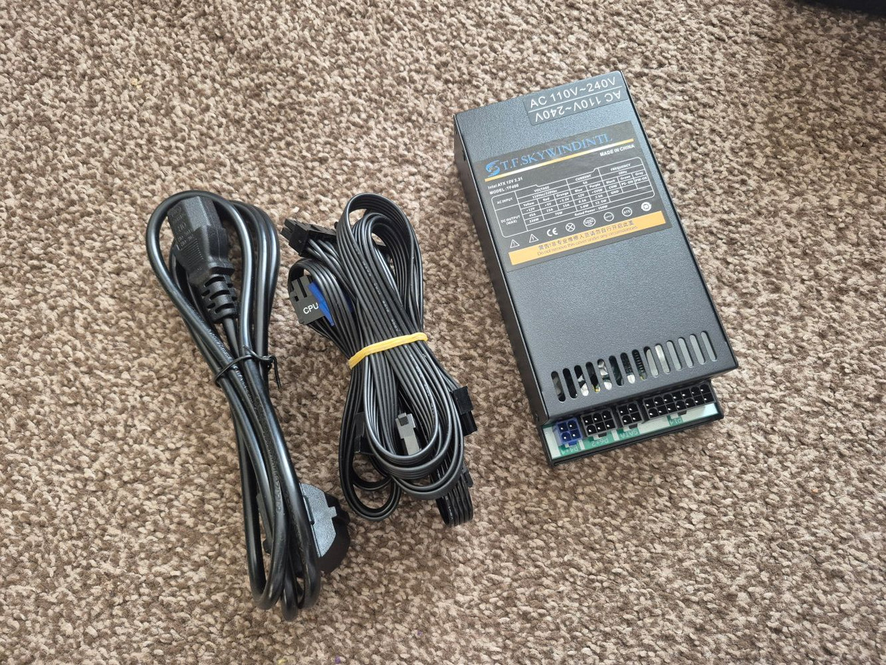
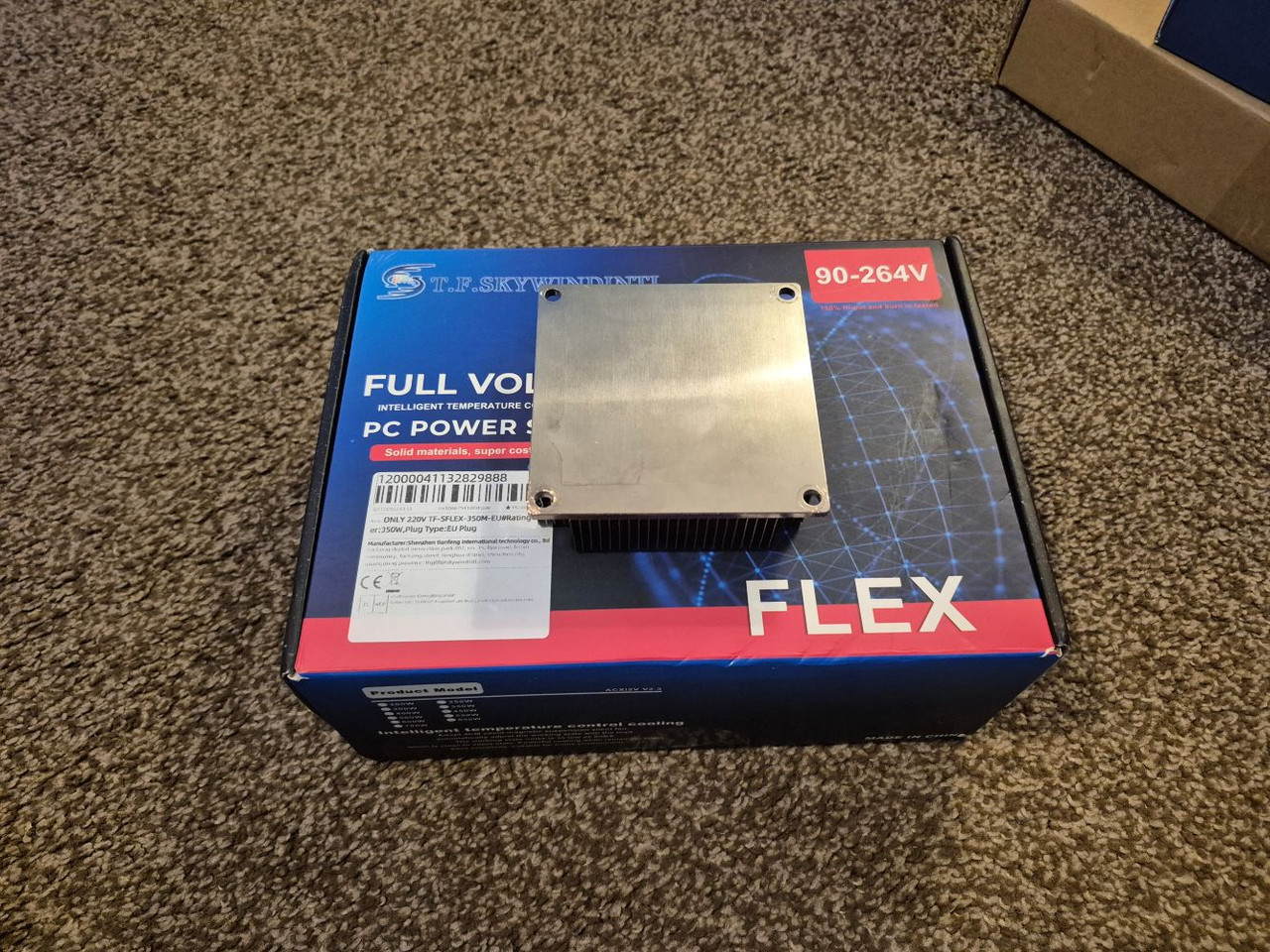
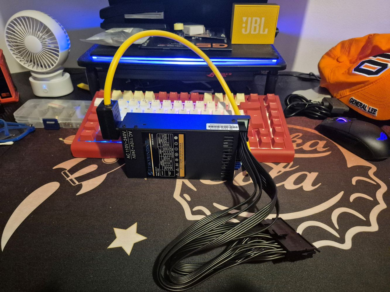
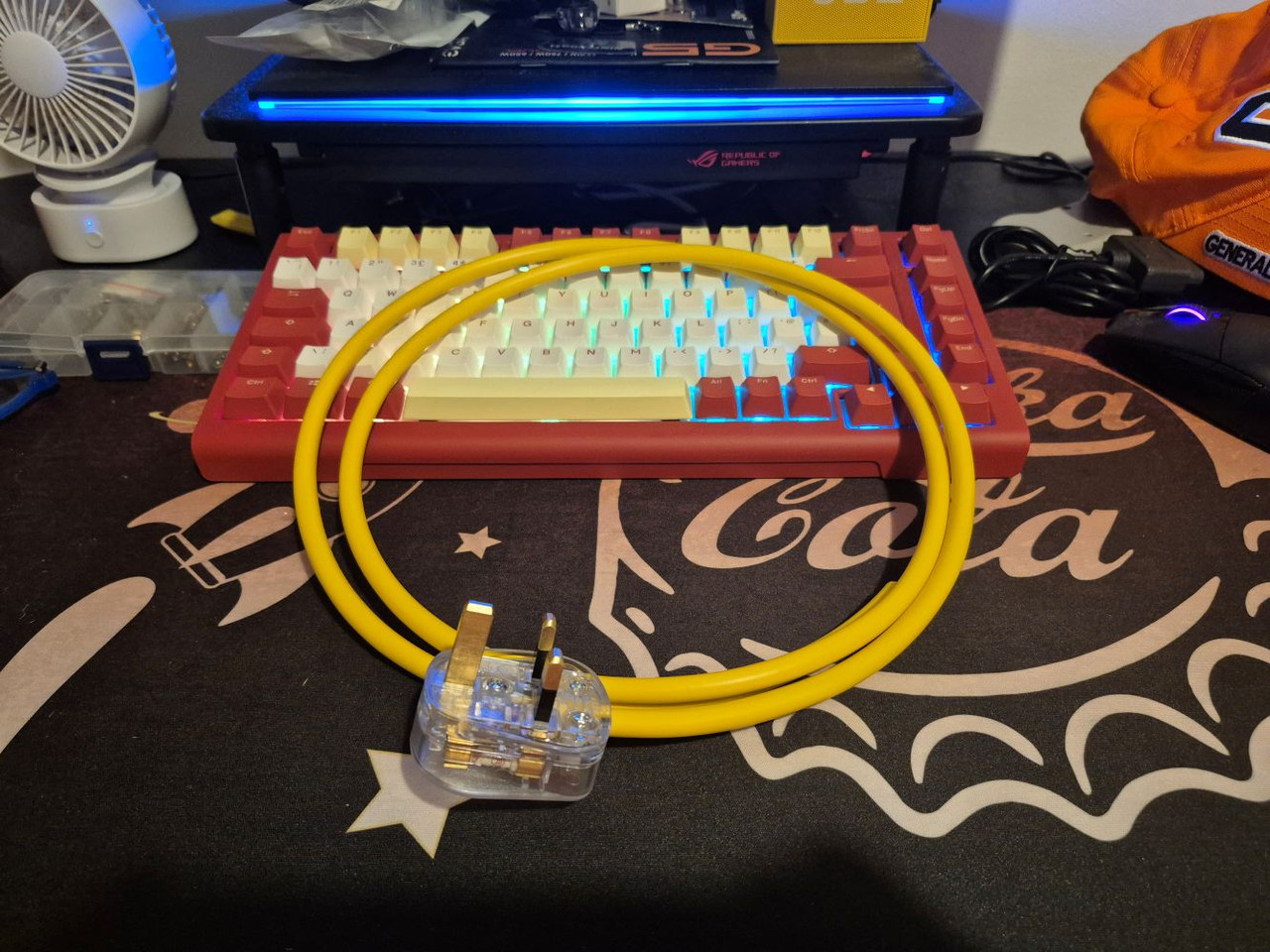
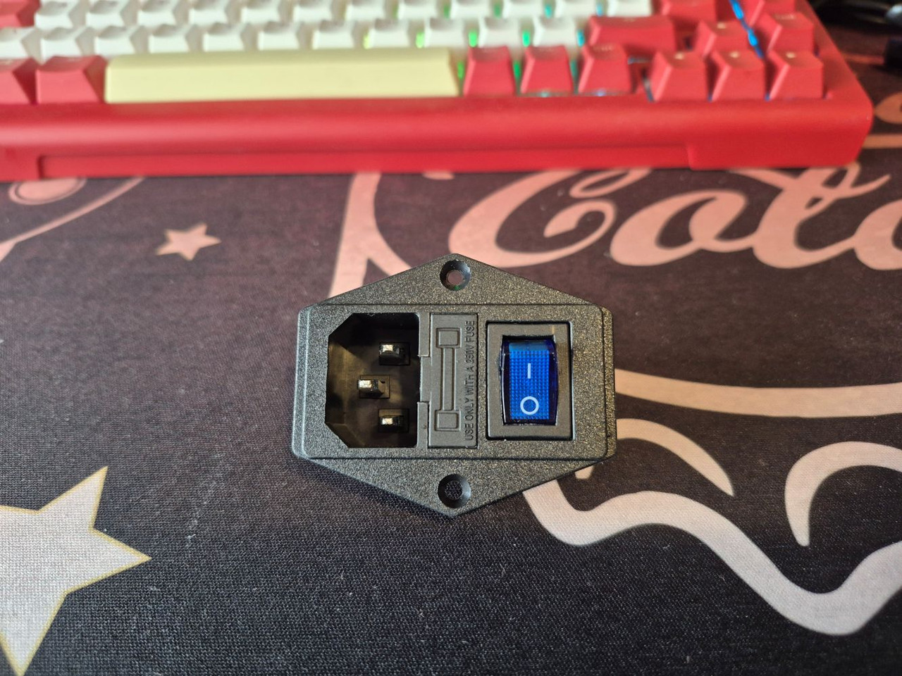
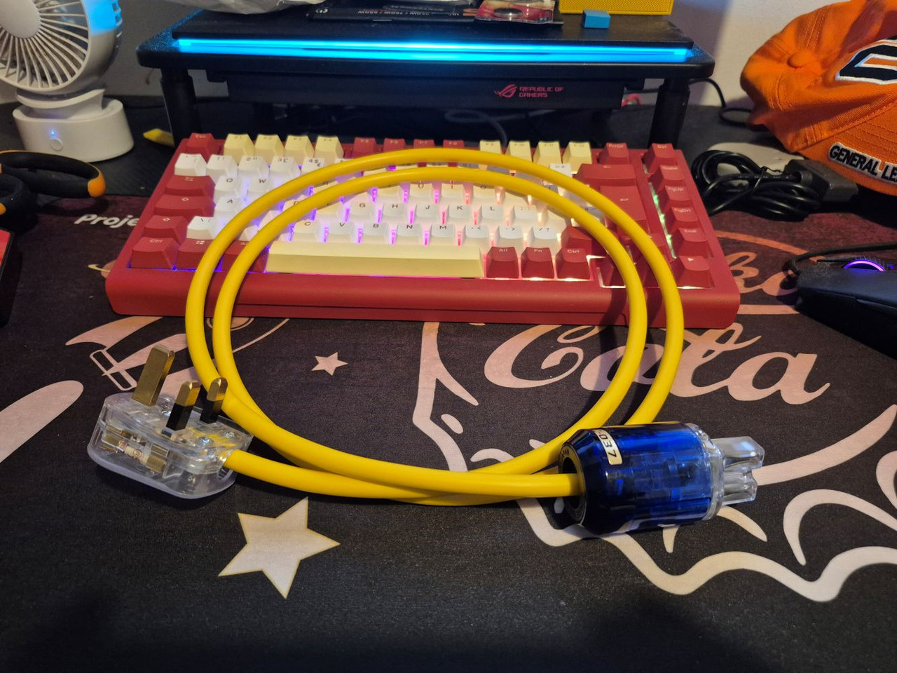
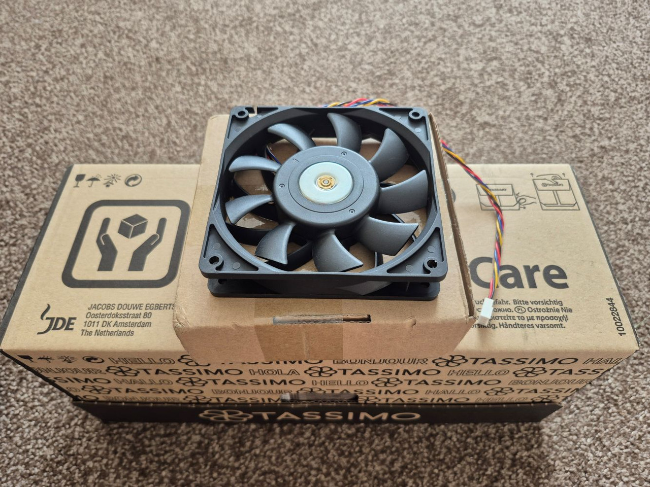
It is a very simple thing to power. You literally just need a PSU. Now I want to keep this thing as small as humanly possible, so I got this.
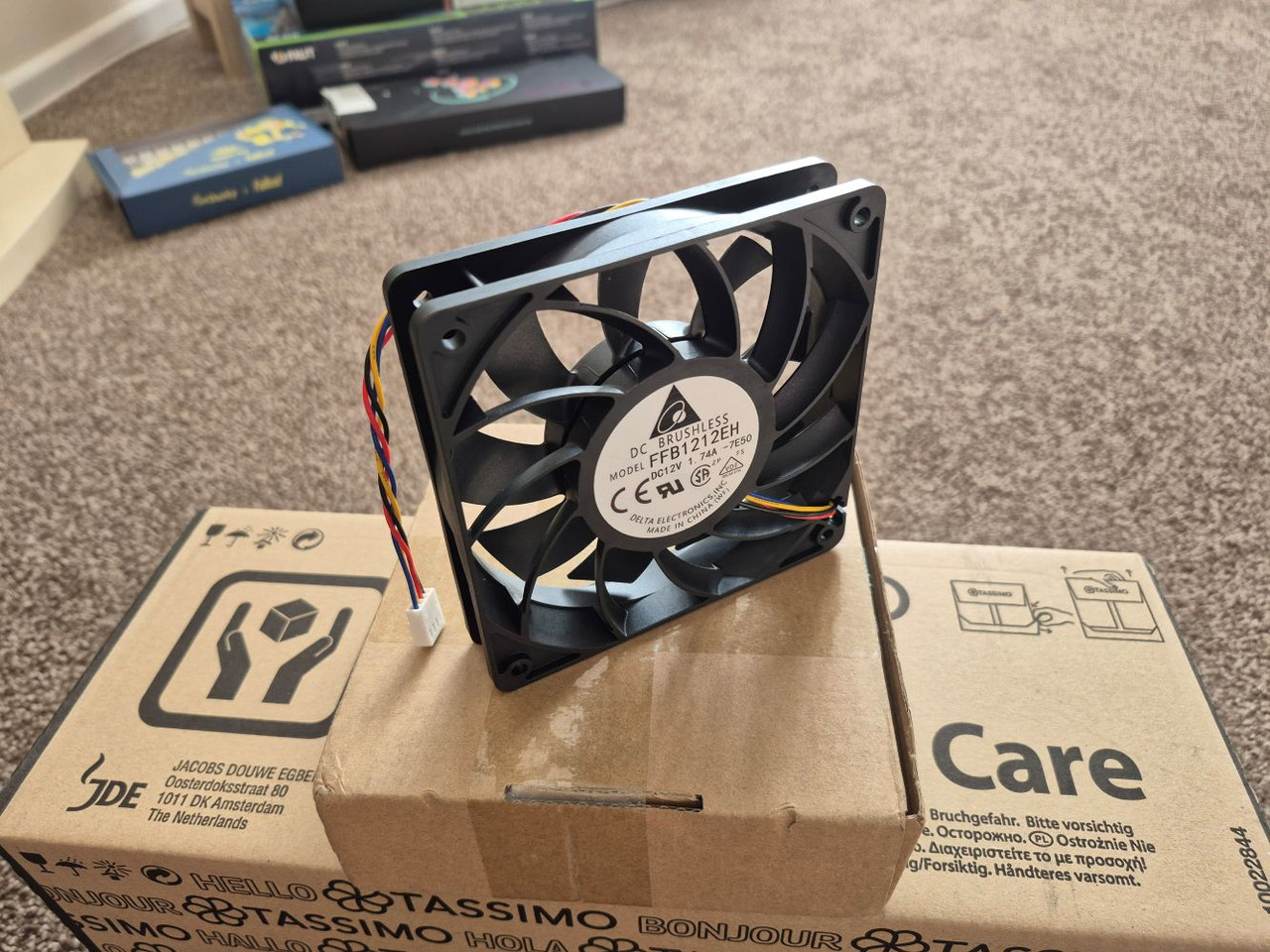
Now these are known for being noisy. However, I have two options. First one is to put a Noctua fan in it. Which will make it silent. The second option? remove the fan completely. This may sound sketchy, but the design of the unit will be such that it will get tons of air shoved through its bottom just like the plane. How? Well, imagine a PC with a front panel that is, IDK, 130mm x 130mm square. With a nice powerful fan in it. Then imagine the PC being the depth of the back plane so you can connect things to it. This design is also known as the wind tunnel. Which, amazingly, is how the server it once lived in would operate. Hamish stuck a fan to the top of it, but that is not how you would go about cooling it.
The plan.
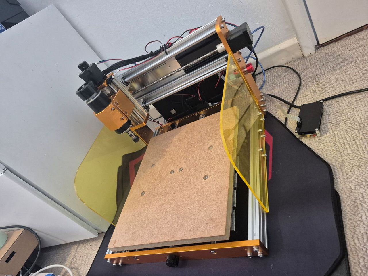
Machine the entire machine from 5mm acrylic, in the Vault Tec colours. Only unlike Modular I will not be relying on these pieces of acrylic to be straight. That was where I went wrong last time. This time around not only will I machine out any vents, details and logos myself but I will also cut the entire panels at the same time using the machine so I know they are all perfectly straight.
The cool part of this all is that it should cost less than 200 quid all done and running. I have been waiting for a project idea for my new CNC since I got it. So far it has machined out a few parts but nothing on this scale.
LFG !!
OK guys, so here is where I am at. I am unsure of the depth needed yet. I may as well wait until it arrives. However, I looked up the data sheet for the Delta fan, and came up with these. I also figured out how I want to hold it all together. I want to use M4 bolts, tapped into the plastic. However, for that you need some thick plastic. As such I decided the front and back will be doubled up 5mm acrylic, plastic welded, giving me 10mm to tap into. I should have done this with Modular, but figured I could glue it. Nightmare that was !
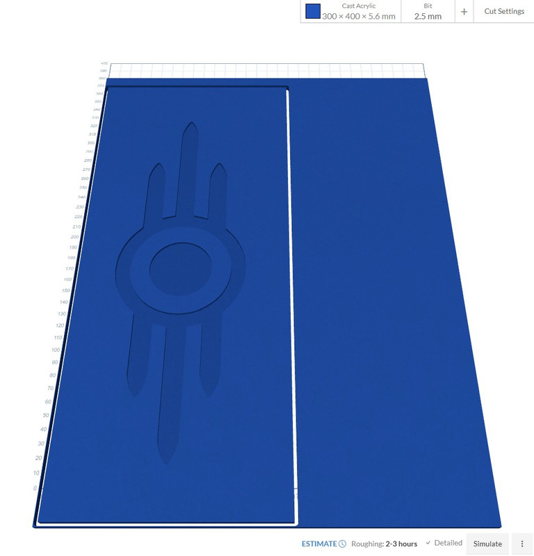
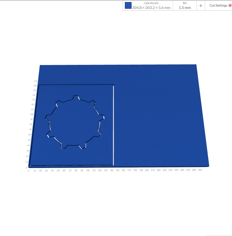
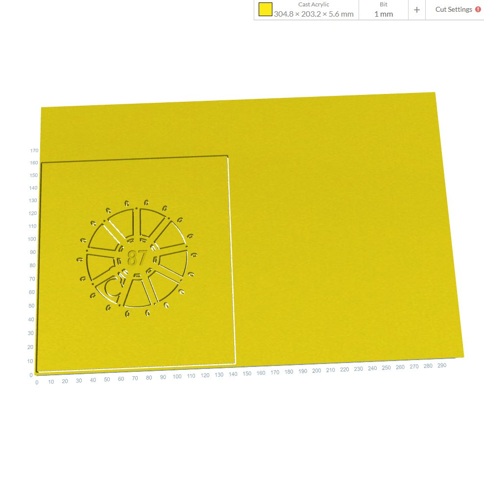
So this one will be the outer panel. It will be blue. I will put these into the CNC software soon and post some images of what it should look like as a piece. However, for right now just use your imagination.
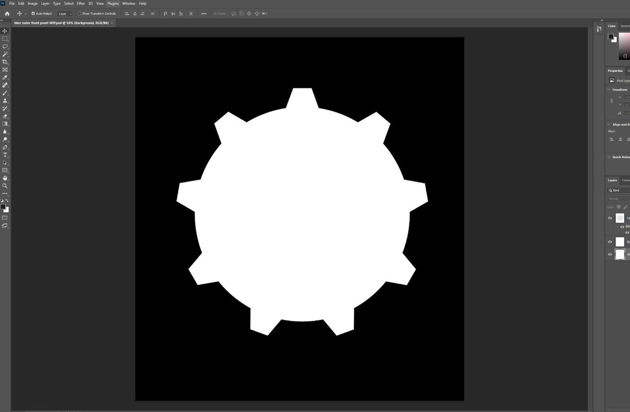
That part was reasonably easy tbh. Just find an image, trace it as a vector, put it back as a EPS so I can work on it in Photoshop and yeah. 10 min jobber. This one on the other hand started out life looking nothing like this. Had I ran the machine it would have fallen to bits. As such I had to basically draw in a load of pieces to attach it making it one solid piece.
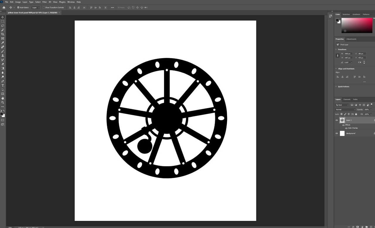
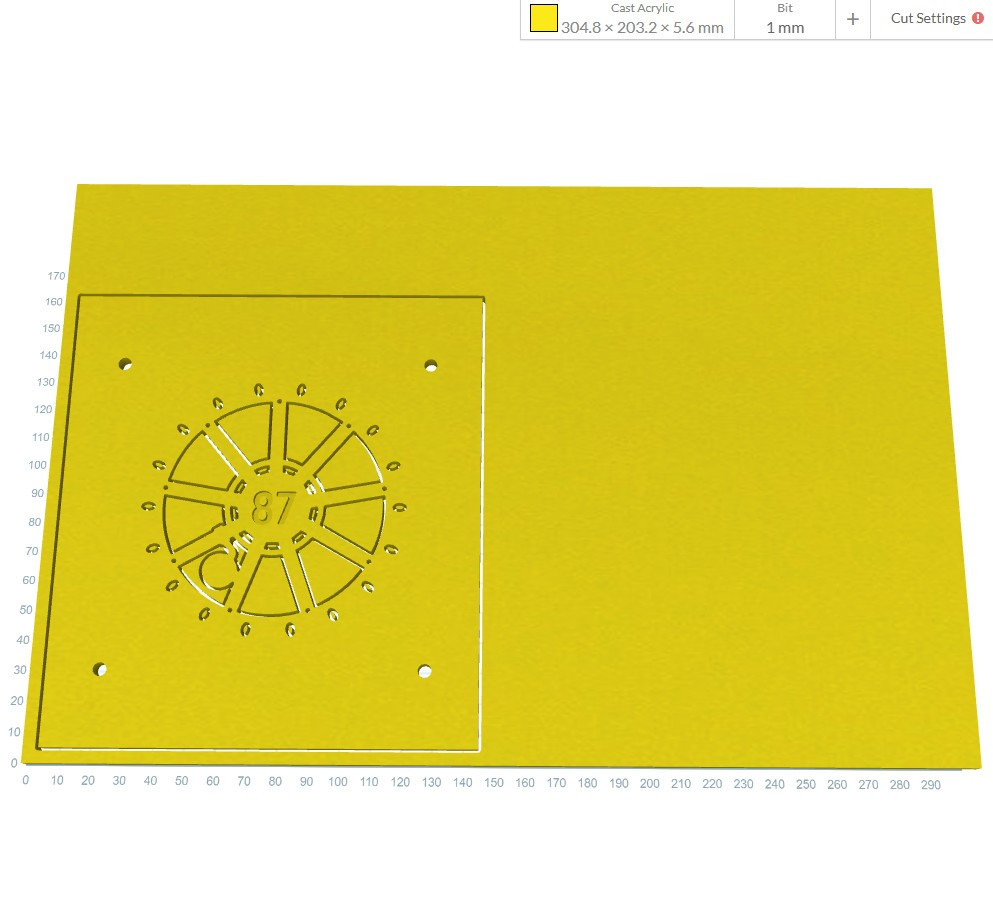
And then I could fill it in.
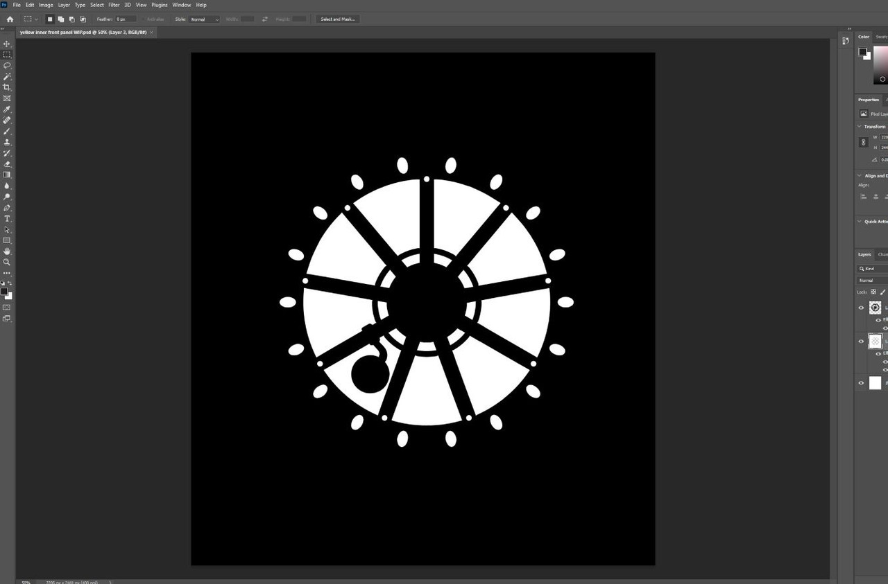
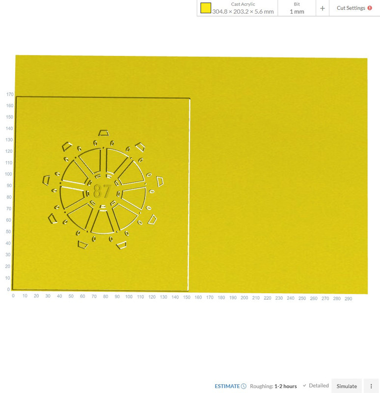
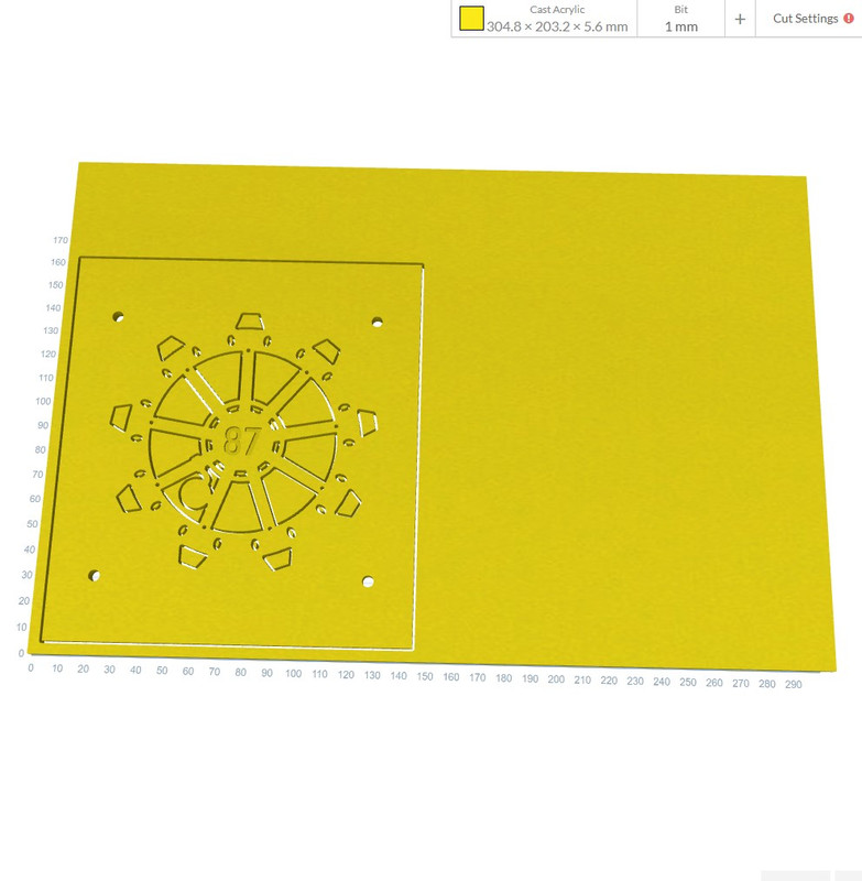
So imagine that the first pic will be a piece of 5mm blue. The piece above in the last pic will be in yellow, and will be plastic welded directly below the blue layer.
Don't worry, I will be putting a vault door number in the middle (87...) but that will come later, as anything in the image right now will machine all the way through. Again this would cause the number to basically fall out (pardon the pun !) so I need it as a separate object I can engrave in, rather than cutting out.
I hope that makes sense...
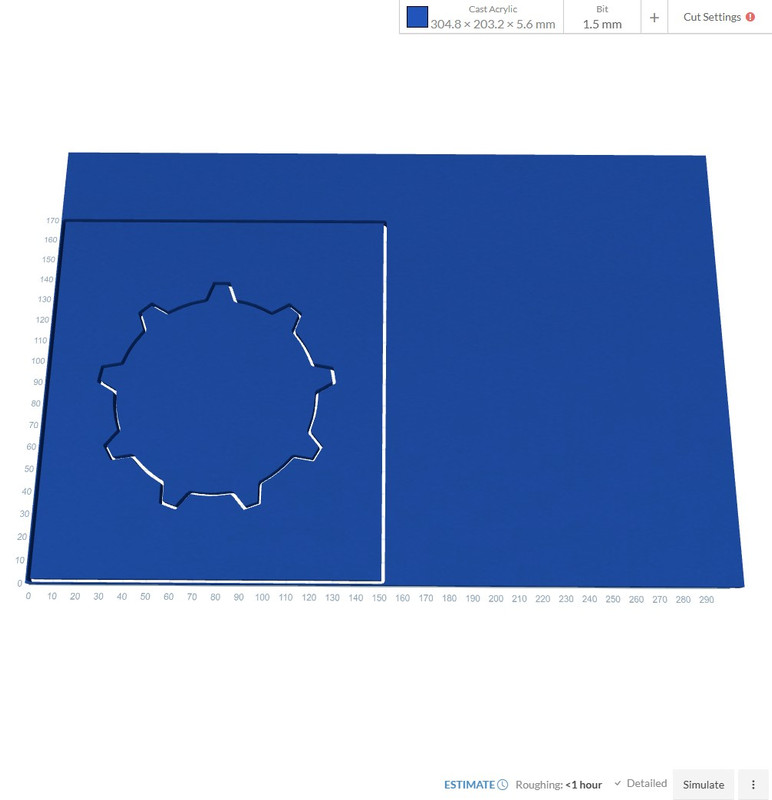
The back also will be two pieces. These will be the anchor points for the top, bottom and both sides to screw into. I may well bond a couple of them also, leaving the ones needed to access the hardware. However, what I am dead set on is M4 screws.
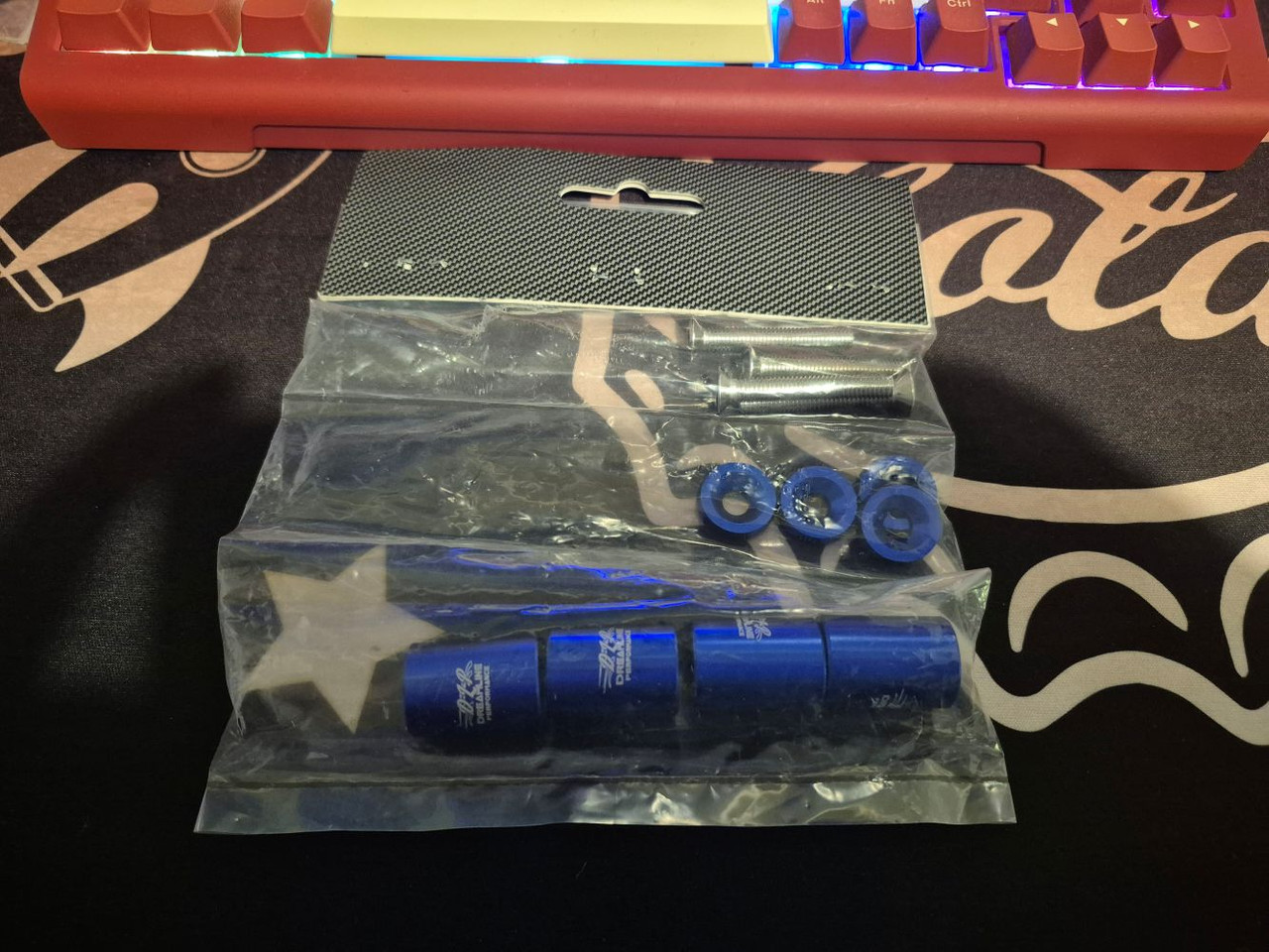
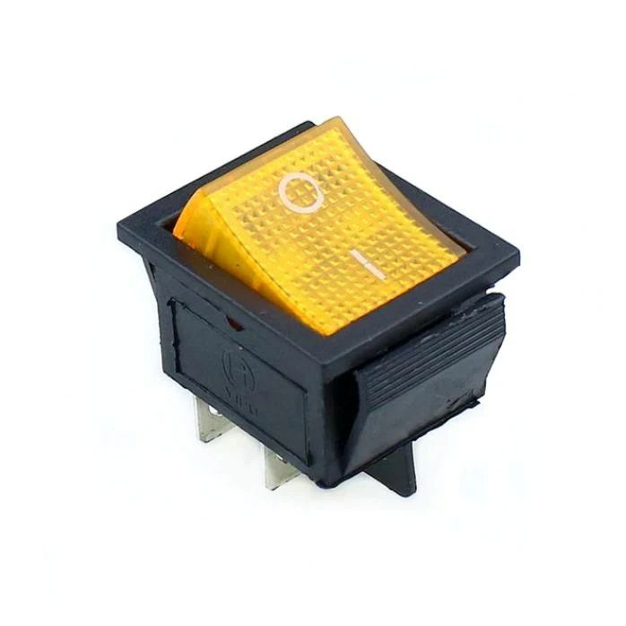
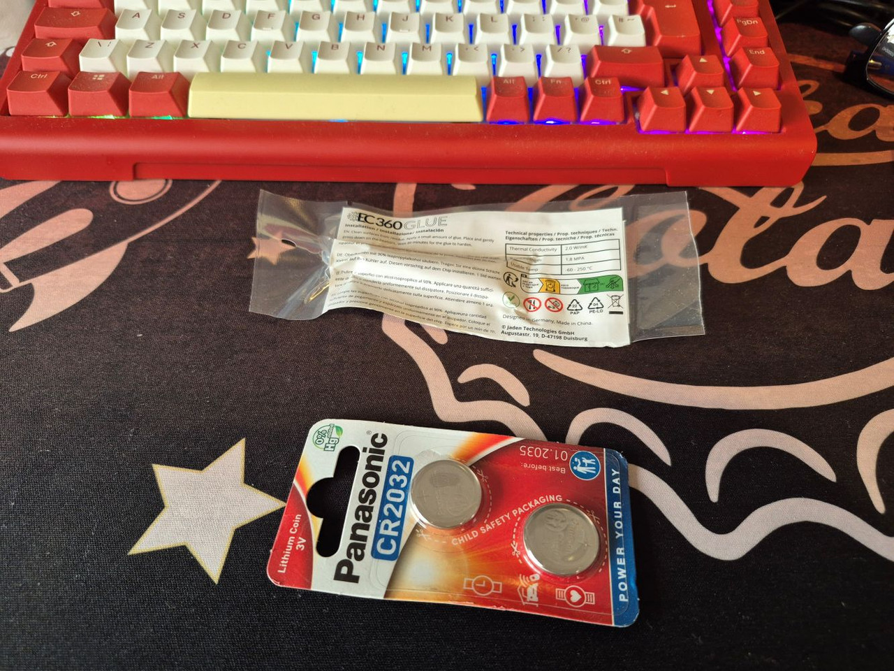
I have also been looking into ways to tame that beast of a fan. I found this. It is 3a capable, so more than enough to run the one single fan.
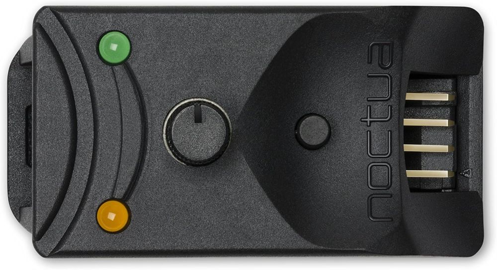
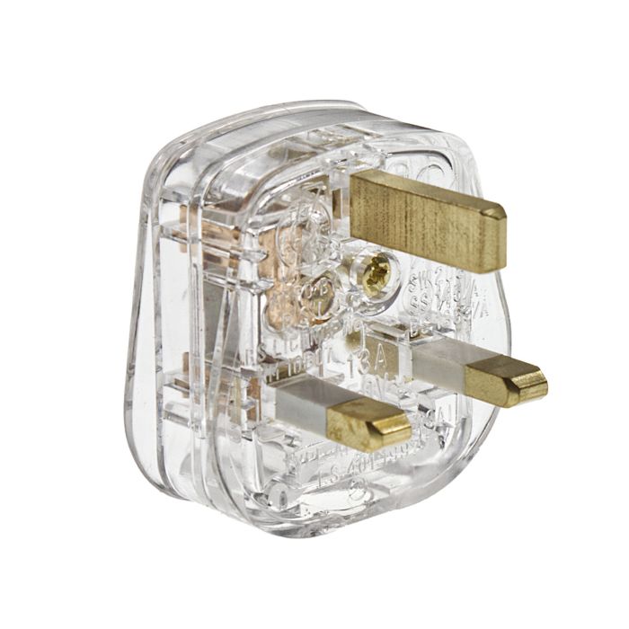
I can then manually set it. I also just ordered one of these. Again, this will be part of the wind tunnel. Overkill absolutely but it was cheap (11 quid) and will work very well.
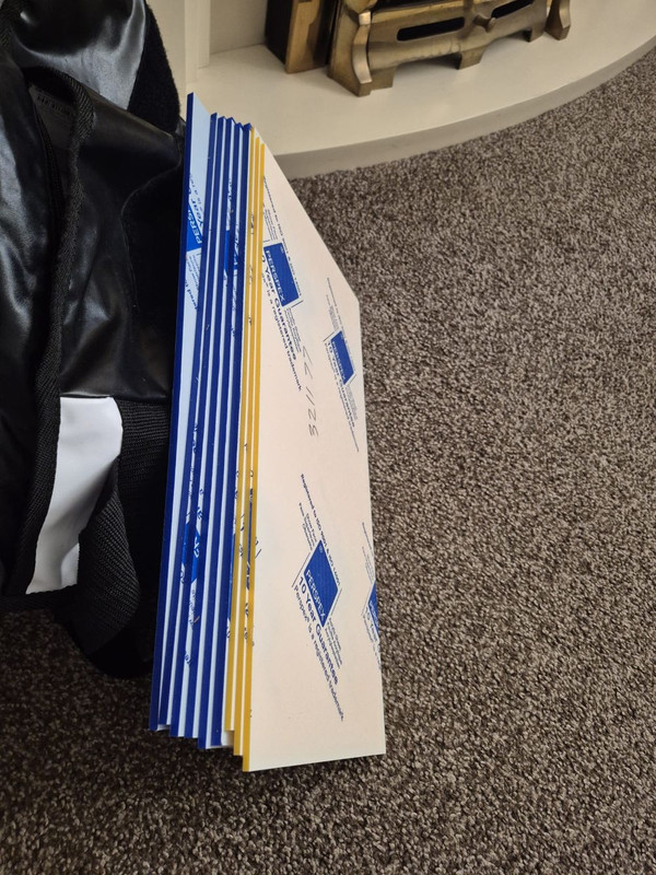
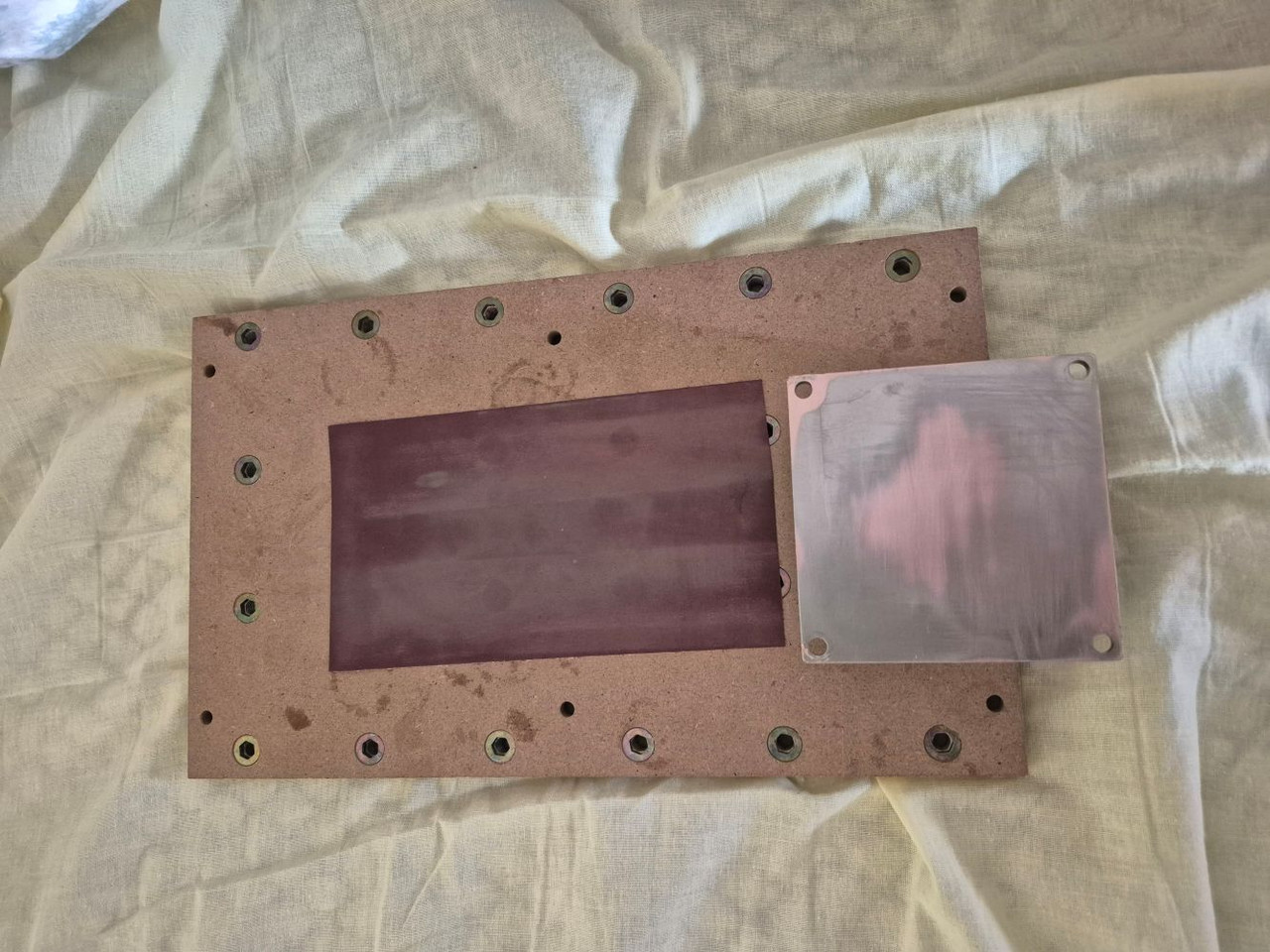
The only other thing purchased is this.
Now you may be wondering what the heck that has to do with anything. Well usually I use a special (and expensive) double sided masking tape called Kipp. It's awesome. However, I usually use old brown card envelopes from that place on the internet you buy crap from. Problem is they can be uneven etc. So I finally decided to buy something suited.
Basically it should be about a mil thick. You double side it down to the bed, and then double side the top to hold down the acrylic. It gives you some breathing space when you go through the acylic without dragging the bit through the spoil board. Which would, over time, reduce the ability to stick things down fully as you would have air channels.
So what in tarnation is a G.E.C.K? well any one who played Fallout 3 to completion will know. It is located in Vault 87 and you need it for Project Purity. It has something to do with farming and vitality of land, but more importantly it filters water from radiation etc making it safe. This is a GECK.
However, it also stands for something else. After Fallout 3 launched Bethesda released a tool for modders to make quests and items with. The Garden Of Eden Creation Kit. Very clever.
So what is my GECK for and what will it do? hilariously it will be a working computer (running Linux, it does not work with Windows **yet**) that is built solely for the playing of Fallout games.
And this is where it gets very different indeed.
So yes yesterday I was watching the tube of poo and a video popped up from Hamish, AKA Budget Builds Official. I mean no disrespect here but I don't sub to his channel because it is mostly him playing with cheap crap (literally) for lots of views. Picking the peanuts out of poo is not something I would normally partake in so yeah.
However, yesterday he posted what is, IMO, his most interesting video yet. Basically he got hold of a back plane that was built for mining that contains a Ryzen APU (most specifically the one from the PS5) as well as 16gb memory and etc. IE, a whole PC on a back plane. This.
It is dual slot and about the size of a GPU. Yet, it is an entire computer on a single board. Couple more pics.
It is a very simple thing to power. You literally just need a PSU. Now I want to keep this thing as small as humanly possible, so I got this.
Now these are known for being noisy. However, I have two options. First one is to put a Noctua fan in it. Which will make it silent. The second option? remove the fan completely. This may sound sketchy, but the design of the unit will be such that it will get tons of air shoved through its bottom just like the plane. How? Well, imagine a PC with a front panel that is, IDK, 130mm x 130mm square. With a nice powerful fan in it. Then imagine the PC being the depth of the back plane so you can connect things to it. This design is also known as the wind tunnel. Which, amazingly, is how the server it once lived in would operate. Hamish stuck a fan to the top of it, but that is not how you would go about cooling it.
The plan.
Machine the entire machine from 5mm acrylic, in the Vault Tec colours. Only unlike Modular I will not be relying on these pieces of acrylic to be straight. That was where I went wrong last time. This time around not only will I machine out any vents, details and logos myself but I will also cut the entire panels at the same time using the machine so I know they are all perfectly straight.
The cool part of this all is that it should cost less than 200 quid all done and running. I have been waiting for a project idea for my new CNC since I got it. So far it has machined out a few parts but nothing on this scale.
LFG !!
OK guys, so here is where I am at. I am unsure of the depth needed yet. I may as well wait until it arrives. However, I looked up the data sheet for the Delta fan, and came up with these. I also figured out how I want to hold it all together. I want to use M4 bolts, tapped into the plastic. However, for that you need some thick plastic. As such I decided the front and back will be doubled up 5mm acrylic, plastic welded, giving me 10mm to tap into. I should have done this with Modular, but figured I could glue it. Nightmare that was !
So this one will be the outer panel. It will be blue. I will put these into the CNC software soon and post some images of what it should look like as a piece. However, for right now just use your imagination.
That part was reasonably easy tbh. Just find an image, trace it as a vector, put it back as a EPS so I can work on it in Photoshop and yeah. 10 min jobber. This one on the other hand started out life looking nothing like this. Had I ran the machine it would have fallen to bits. As such I had to basically draw in a load of pieces to attach it making it one solid piece.
And then I could fill it in.
So imagine that the first pic will be a piece of 5mm blue. The piece above in the last pic will be in yellow, and will be plastic welded directly below the blue layer.
Don't worry, I will be putting a vault door number in the middle (87...) but that will come later, as anything in the image right now will machine all the way through. Again this would cause the number to basically fall out (pardon the pun !) so I need it as a separate object I can engrave in, rather than cutting out.
I hope that makes sense...
The back also will be two pieces. These will be the anchor points for the top, bottom and both sides to screw into. I may well bond a couple of them also, leaving the ones needed to access the hardware. However, what I am dead set on is M4 screws.
I have also been looking into ways to tame that beast of a fan. I found this. It is 3a capable, so more than enough to run the one single fan.
I can then manually set it. I also just ordered one of these. Again, this will be part of the wind tunnel. Overkill absolutely but it was cheap (11 quid) and will work very well.
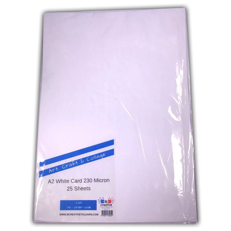
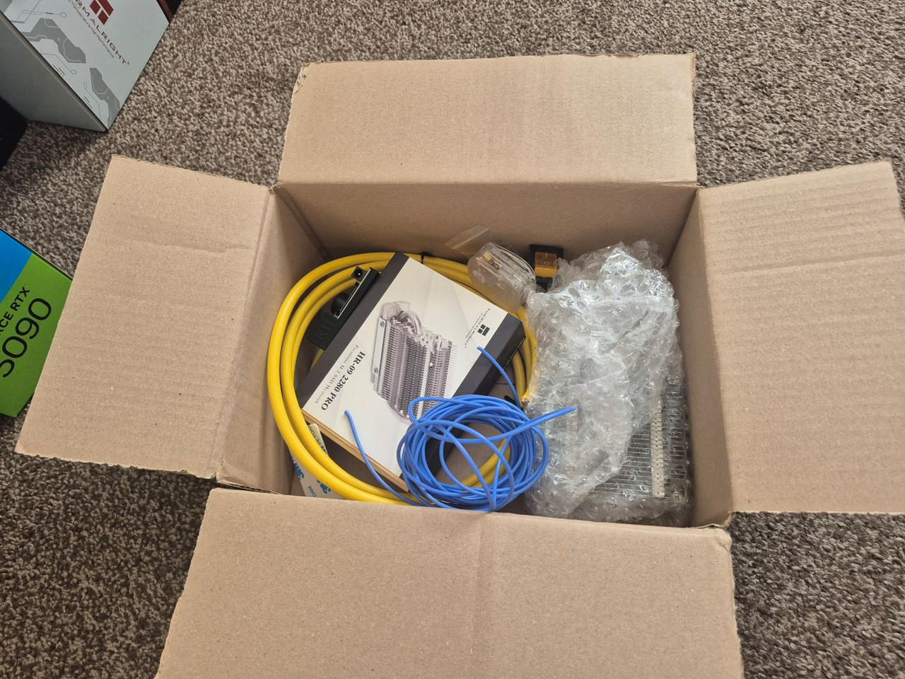
The only other thing purchased is this.
Now you may be wondering what the heck that has to do with anything. Well usually I use a special (and expensive) double sided masking tape called Kipp. It's awesome. However, I usually use old brown card envelopes from that place on the internet you buy crap from. Problem is they can be uneven etc. So I finally decided to buy something suited.
Basically it should be about a mil thick. You double side it down to the bed, and then double side the top to hold down the acrylic. It gives you some breathing space when you go through the acylic without dragging the bit through the spoil board. Which would, over time, reduce the ability to stick things down fully as you would have air channels.


")