You are using an out of date browser. It may not display this or other websites correctly.
You should upgrade or use an alternative browser.
You should upgrade or use an alternative browser.
[Scratch build] Floating Cave
- Thread starter mr.maler
- Start date
WYP
News Guru
Sorry for the lack of updates! Had no time to work on it, we found and bought a house on short notice. The renovation will take some time, but after it's done I'm going to come back to my floating cave!
I hope the renovations go well dude. I look forward to seeing how this build progresses when you get back to it.
Long time no see! Renovations went well ")
My Floating Cave survived all the moving without any harms. It just got very dusty J
Started my re-entry with the motherboard. I decided to remove all the blue. All the RGB-LEDs don’t make any sense, if there’s already a color theme.
The status quo:
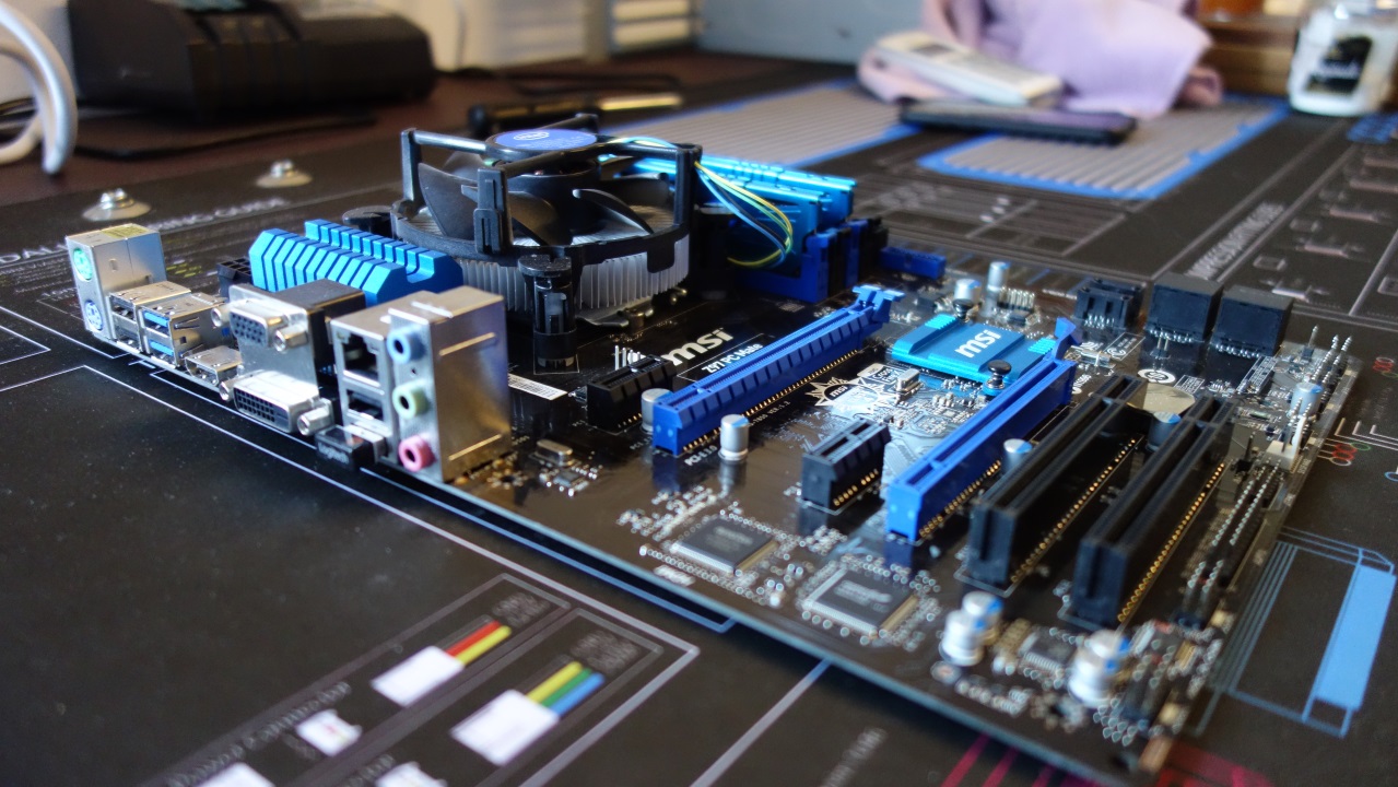
A lot of blue to remove. First I removed all heat sinks.

The heat gun was very useful for the RAM heat spreaders.
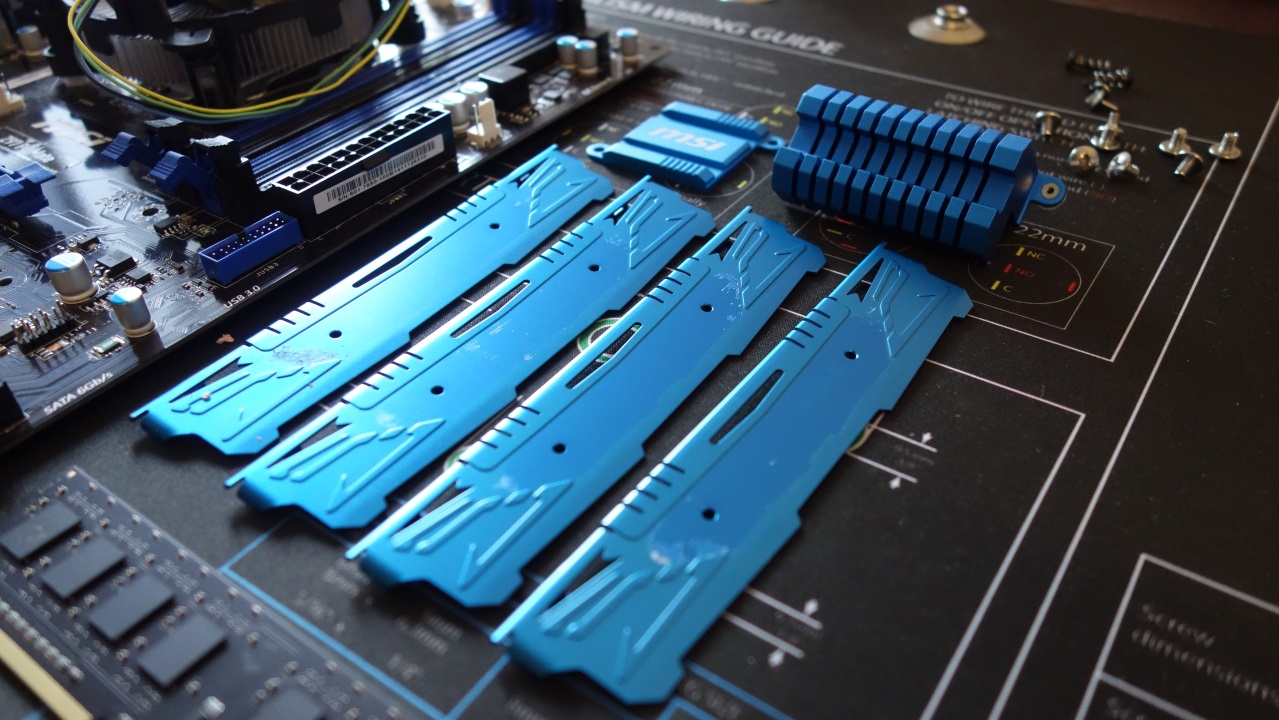
I cleaned the aluminium parts and used hot sodium hydroxide to remove the anodization. Worked very well. But quite dangerous, always wear protection gloves, safety glasses and respiratory protection. This is why I couldn’t manage to take some photos.
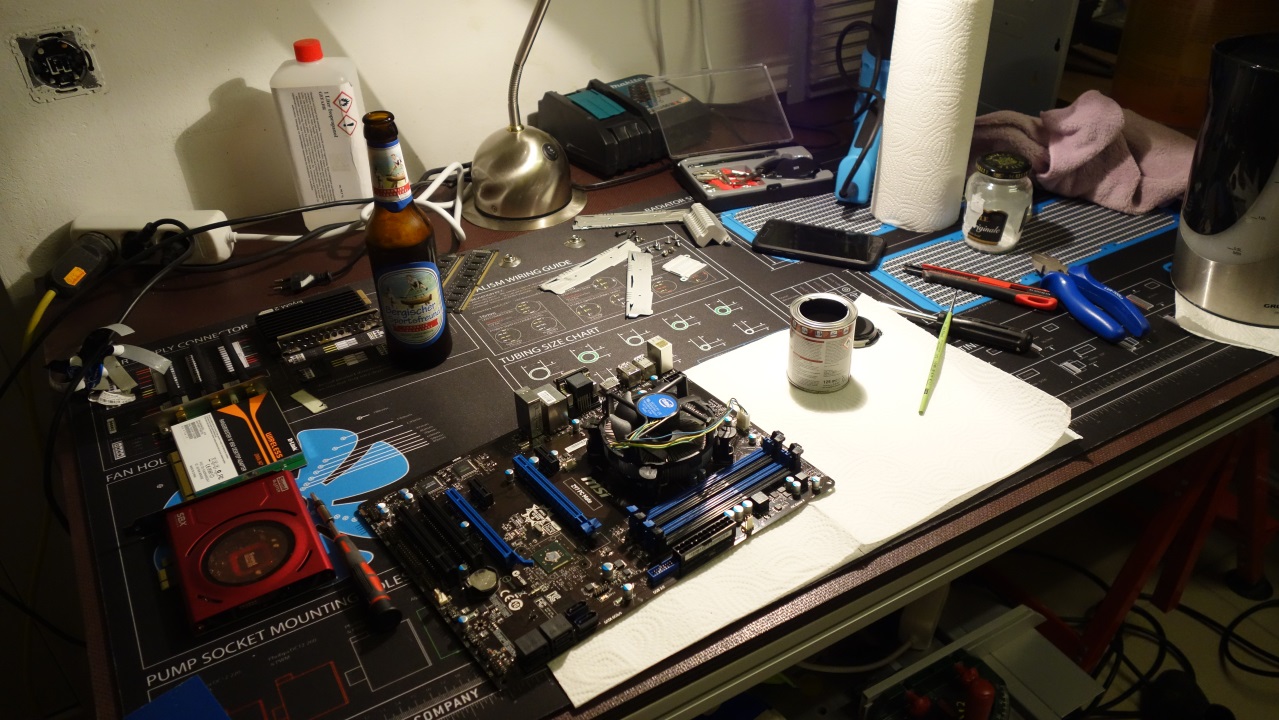
I colored the plastic parts of the motherboard with a synthetic resin varnish. I’ll have to do it a second time to clear all the imperfections.
Decided to not use the RAM heat spreaders again. They do not fit into my design concept. In my opinion, they look way better naked.

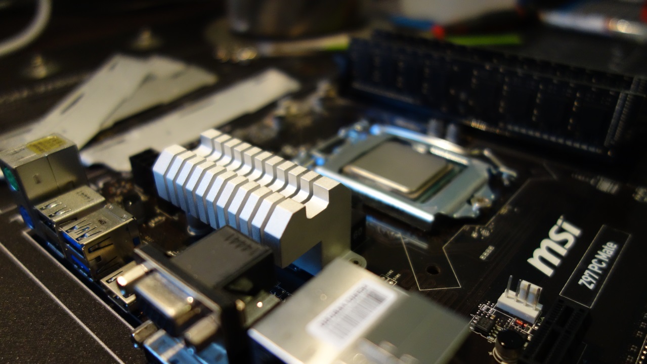

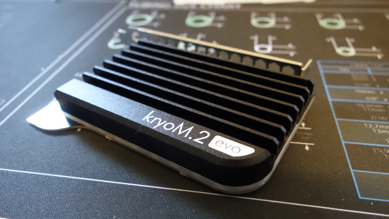
I removed the old HDD and replaced it with a Samsung 970 evo m.2. Needed an adapter for it. Luckily, there is one who matches my design concept nearly perfectly.
Time keeps short the next months, cannot say when I’m going to do the next update!
My Floating Cave survived all the moving without any harms. It just got very dusty J
Started my re-entry with the motherboard. I decided to remove all the blue. All the RGB-LEDs don’t make any sense, if there’s already a color theme.
The status quo:

A lot of blue to remove. First I removed all heat sinks.

The heat gun was very useful for the RAM heat spreaders.

I cleaned the aluminium parts and used hot sodium hydroxide to remove the anodization. Worked very well. But quite dangerous, always wear protection gloves, safety glasses and respiratory protection. This is why I couldn’t manage to take some photos.
I colored the plastic parts of the motherboard with a synthetic resin varnish. I’ll have to do it a second time to clear all the imperfections.

Decided to not use the RAM heat spreaders again. They do not fit into my design concept. In my opinion, they look way better naked.


I removed the old HDD and replaced it with a Samsung 970 evo m.2. Needed an adapter for it. Luckily, there is one who matches my design concept nearly perfectly.

Time keeps short the next months, cannot say when I’m going to do the next update!
C'mon dude, don't leave us hangin'. Can't believe I missed this build log - love scratch builds. Have just read it from start to finish, looks fantastic - needs that final push to finish it.
Thanks man! I'll do my very best
 Nobody wants to see it finished more than I do!
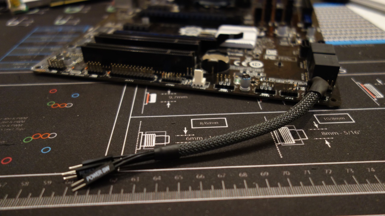
Had a free Saturday which i spend on the Floating Cave. The MB got a second painting. Now there’s no blue left (with mounted components). I soldered a custom made extension to the connectors for power-button etc.
The color of the sound card did not match the theme. First I removed the cover.

The sound processor got painted. A 3D-foil was used for masking the cover.
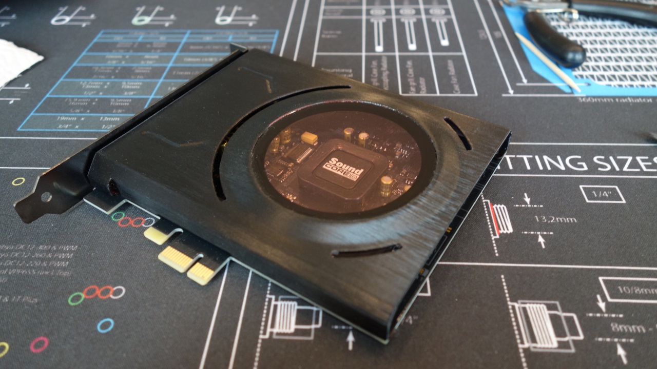
Unfortunately, the disc has a slight reddish tinge. Let's see, maybe I'll exchange them. I simply removed the two red illumination LEDs on the soundcard.
Then we went to the graphics card: the extensions of the power supply got sleeved and completed.
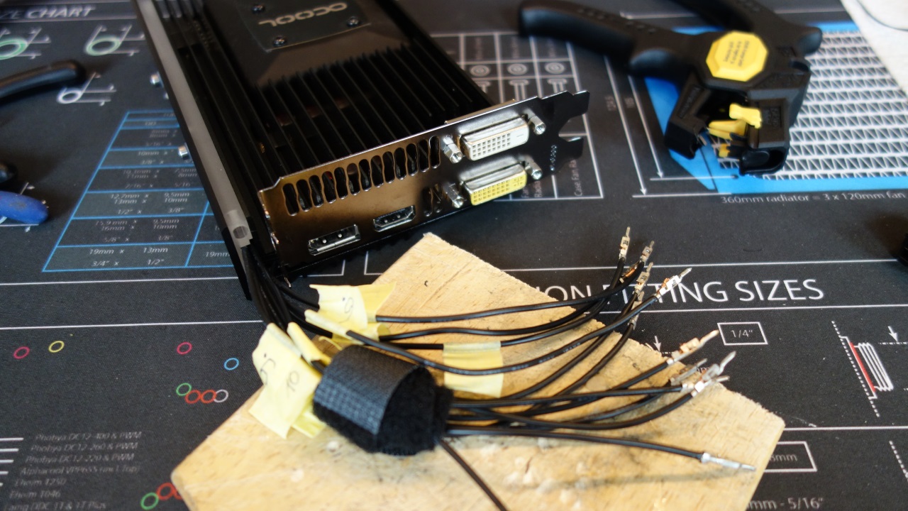
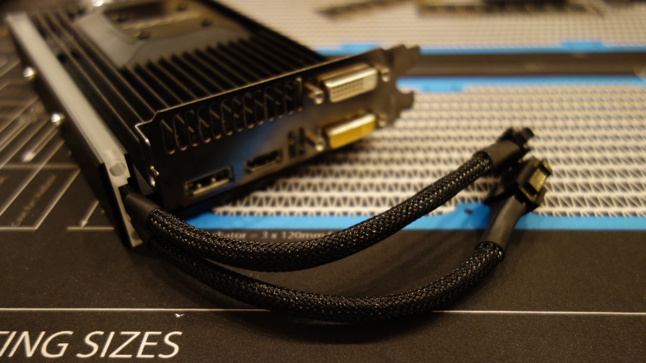
I also replaced the screws of the self-made cover.
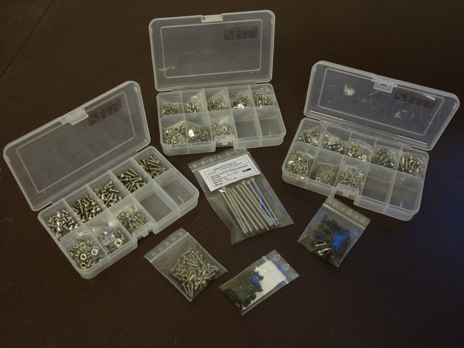
Was shopping and have increased my assortment stainless steel screws. But it was especially hard to find a few special screws that I needed for the case.
Here again the status quo of the case:


Actually, not much is missing for the move of the computer. I have already tested the majority of the loop in order to test the tightness of the components. Especially the quick couplings that were now dry for a long time. The good news: everything is tight. But I had big problems with the bleeding. The position of the pump with the small elevation loop compared to the AGB is conceivably bad. Inlet and outlet of the AGB at the same height prevent a clean full running of the lower components. As a test, I mounted the inlet at the lid. It was much better. Now I have to see if I manage to get in the lid a nice solution for water intake.

The color of the sound card did not match the theme. First I removed the cover.

The sound processor got painted. A 3D-foil was used for masking the cover.

Unfortunately, the disc has a slight reddish tinge. Let's see, maybe I'll exchange them. I simply removed the two red illumination LEDs on the soundcard.
Then we went to the graphics card: the extensions of the power supply got sleeved and completed.


I also replaced the screws of the self-made cover.

Was shopping and have increased my assortment stainless steel screws. But it was especially hard to find a few special screws that I needed for the case.

Here again the status quo of the case:


Actually, not much is missing for the move of the computer. I have already tested the majority of the loop in order to test the tightness of the components. Especially the quick couplings that were now dry for a long time. The good news: everything is tight. But I had big problems with the bleeding. The position of the pump with the small elevation loop compared to the AGB is conceivably bad. Inlet and outlet of the AGB at the same height prevent a clean full running of the lower components. As a test, I mounted the inlet at the lid. It was much better. Now I have to see if I manage to get in the lid a nice solution for water intake.
[FONT="]Happy New Year to you all![/FONT]
[FONT="]I think the Floating Cave can now be considered a long-term project without exaggeration.... In the last two years I really did nothing at all on it. Family, house and job always came first. Thanks to my GPU being removed for three years now, I couldn't even do any gaming to relax![/FONT]
[FONT="]This December it finally went on. [/FONT]
[FONT="]The second radiator still needed brackets. I milled them according to the same scheme as the first one. Then I filed the needed steel inserts and pasted them with decorative foil.[/FONT]
[FONT="] [/FONT]
[FONT="] [/FONT]
[FONT="]Due to time constraints, I refrained with a heavy heart from adding the self-made magnetic caps to the fans of the second radiator as well. I merged the cables of the fans of both radiators into one. However, they remained long enough in the non-visible area to be able to remove the fans without problems. With that, my cooling power plant is ready:[/FONT]
[FONT="]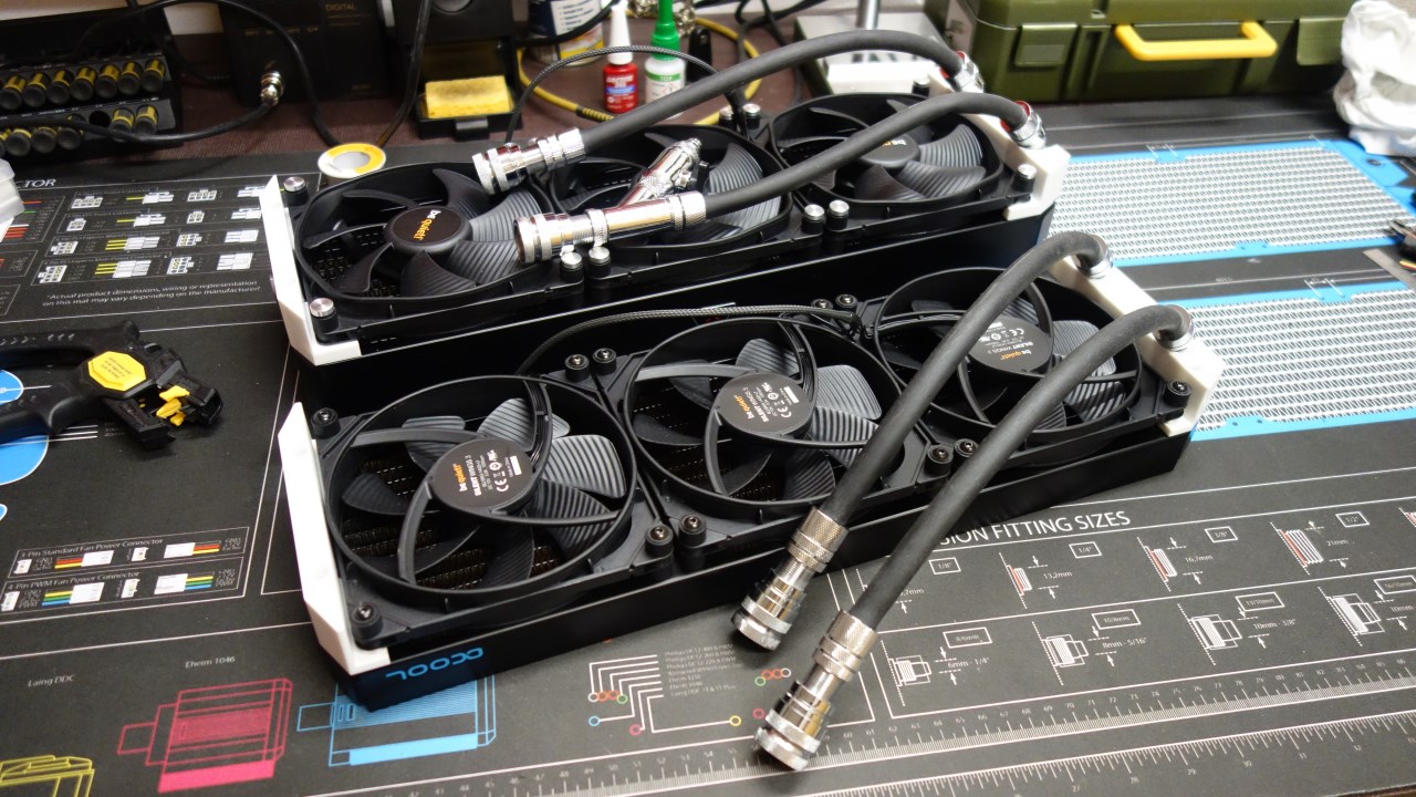 [/FONT]
[FONT="]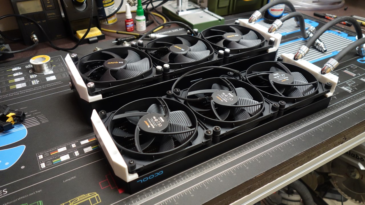 [/FONT]
[FONT="] [/FONT]
[FONT="]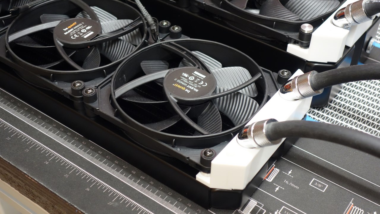 [/FONT]
[FONT="]A view of the "basement", with the front radi disassembled.[/FONT]
[FONT="] [/FONT]
[FONT="]I also redid the pump wiring, it draws power from the power supply, while the speed is controlled by PWM through the Aquaero. [/FONT]
[FONT="] [/FONT]
[FONT="]For the CPU cooler, I opted for a fairly subtle color combination. The cable has been shortened and resleeved as well, of course.[/FONT]
[FONT="] [/FONT]
[FONT="]Then I created the lighting for the fiber optics. This issue almost got on my last nerve. I need 6 LEDs in one strip, plus 2 more in a second. I drilled into the LEDs to get the fiber optics as close to the diode as possible. As tested years ago, this greatly increases the light output. I also coated the LEDs with a chrome varnish so that as little light as possible is lost laterally. [/FONT]
[FONT="] [/FONT]
[FONT="]Then I soldered the 6 LEDs together nicely in parallel and put appropriately powerful resistors in front of them. Who will notice my mistake here?[/FONT]
[FONT="]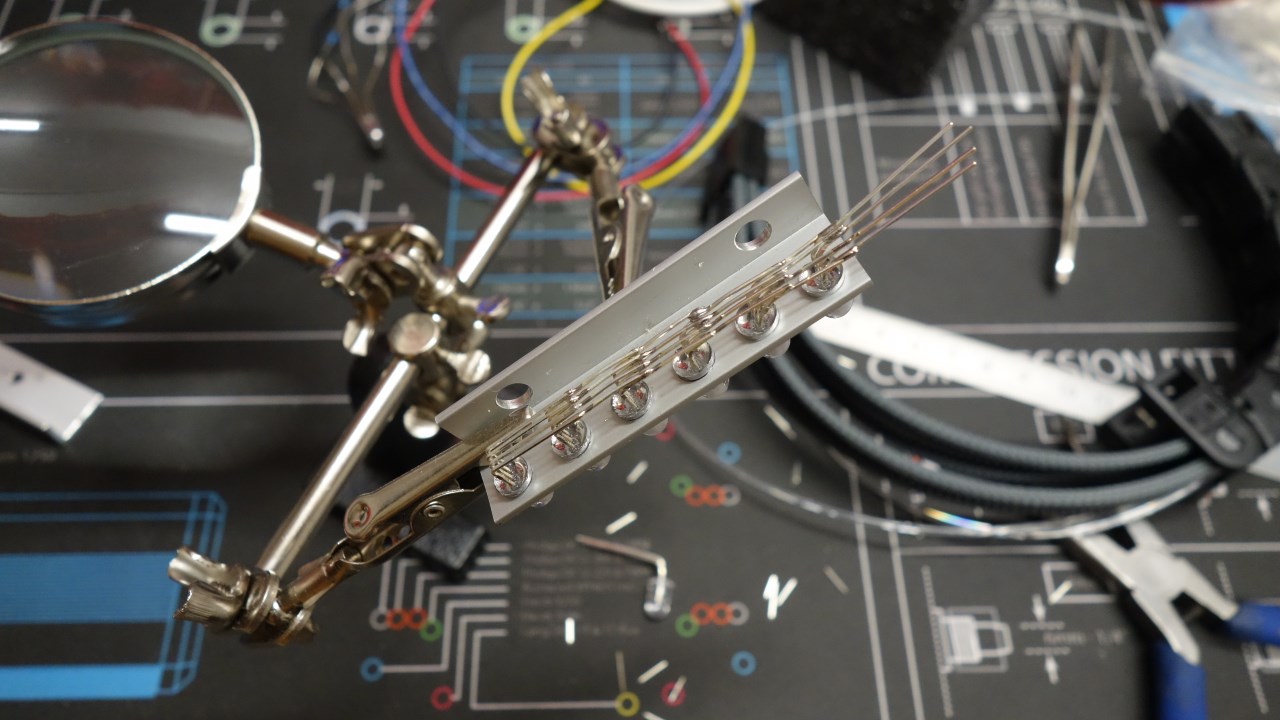 [/FONT]
[FONT="]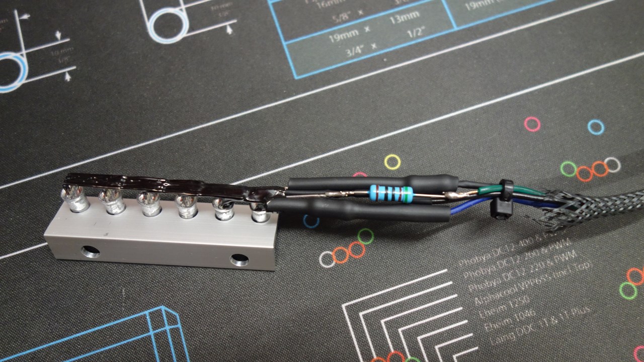 [/FONT]
[FONT="]Fortunately, I ended up testing it. On two of the LEDs one color channel each was defective, I got too deep while drilling. So again the whole thing... and test again. [/FONT]
[FONT="]And this time I wondered why they were all different brightness. So I used the search engine of my trust and found out, that I forgot a lot of things in the last few years, concerning electrical engineering... so for the third time new the whole story. This time each LED got its own 3 resistors. This didn't exactly simplify the soldering....[/FONT]
[FONT="]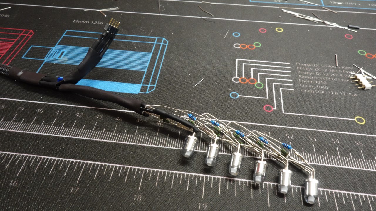 [/FONT]
[FONT="]After that, I dedicated myself to the technology section and created and sleeved all the still missing cables. At the same time, the long-awaited move of the hardware was on the agenda. Finally everything was in its place! Unfortunately I didn't take any pictures of these steps, I was pressed for time and was much too engrossed in the actual implementation. [/FONT]
[FONT="]Only the hardtubing was missing...[/FONT]
[FONT="]I think the Floating Cave can now be considered a long-term project without exaggeration.... In the last two years I really did nothing at all on it. Family, house and job always came first. Thanks to my GPU being removed for three years now, I couldn't even do any gaming to relax![/FONT]
[FONT="]This December it finally went on. [/FONT]
[FONT="]The second radiator still needed brackets. I milled them according to the same scheme as the first one. Then I filed the needed steel inserts and pasted them with decorative foil.[/FONT]
[FONT="]
 [/FONT]
[FONT="]
 [/FONT]
[FONT="]Due to time constraints, I refrained with a heavy heart from adding the self-made magnetic caps to the fans of the second radiator as well. I merged the cables of the fans of both radiators into one. However, they remained long enough in the non-visible area to be able to remove the fans without problems. With that, my cooling power plant is ready:[/FONT]
[FONT="]
 [/FONT]
[FONT="]
 [/FONT]
[FONT="]
 [/FONT]
[FONT="]
 [/FONT]
[FONT="]A view of the "basement", with the front radi disassembled.[/FONT]
[FONT="]
 [/FONT]
[FONT="]I also redid the pump wiring, it draws power from the power supply, while the speed is controlled by PWM through the Aquaero. [/FONT]
[FONT="]
 [/FONT]
[FONT="]For the CPU cooler, I opted for a fairly subtle color combination. The cable has been shortened and resleeved as well, of course.[/FONT]
[FONT="]
 [/FONT]
[FONT="]Then I created the lighting for the fiber optics. This issue almost got on my last nerve. I need 6 LEDs in one strip, plus 2 more in a second. I drilled into the LEDs to get the fiber optics as close to the diode as possible. As tested years ago, this greatly increases the light output. I also coated the LEDs with a chrome varnish so that as little light as possible is lost laterally. [/FONT]
[FONT="]
 [/FONT]
[FONT="]Then I soldered the 6 LEDs together nicely in parallel and put appropriately powerful resistors in front of them. Who will notice my mistake here?[/FONT]
[FONT="]
 [/FONT]
[FONT="]
 [/FONT]
[FONT="]Fortunately, I ended up testing it. On two of the LEDs one color channel each was defective, I got too deep while drilling. So again the whole thing... and test again. [/FONT]
[FONT="]And this time I wondered why they were all different brightness. So I used the search engine of my trust and found out, that I forgot a lot of things in the last few years, concerning electrical engineering... so for the third time new the whole story. This time each LED got its own 3 resistors. This didn't exactly simplify the soldering....[/FONT]
[FONT="]
 [/FONT]
[FONT="]After that, I dedicated myself to the technology section and created and sleeved all the still missing cables. At the same time, the long-awaited move of the hardware was on the agenda. Finally everything was in its place! Unfortunately I didn't take any pictures of these steps, I was pressed for time and was much too engrossed in the actual implementation. [/FONT]
[FONT="]Only the hardtubing was missing...[/FONT]
... to which I have fortunately also still come. Has been my first time with hardtubes. Fortunately, the Alphacool “Eiskoffer” was available to me. It really made my life easier at that point. Nevertheless, I have not only relied on it, but for example, for the measurement of the connection distances also resorted to other tools.

As you can see, I also built a better stand on casters to move the system comfortably and safely. Especially when installing the cables and hardware a big advantage.

The bending needs to be practiced. I'm definitely not a natural at it, and I've produced a fair amount of scrap.
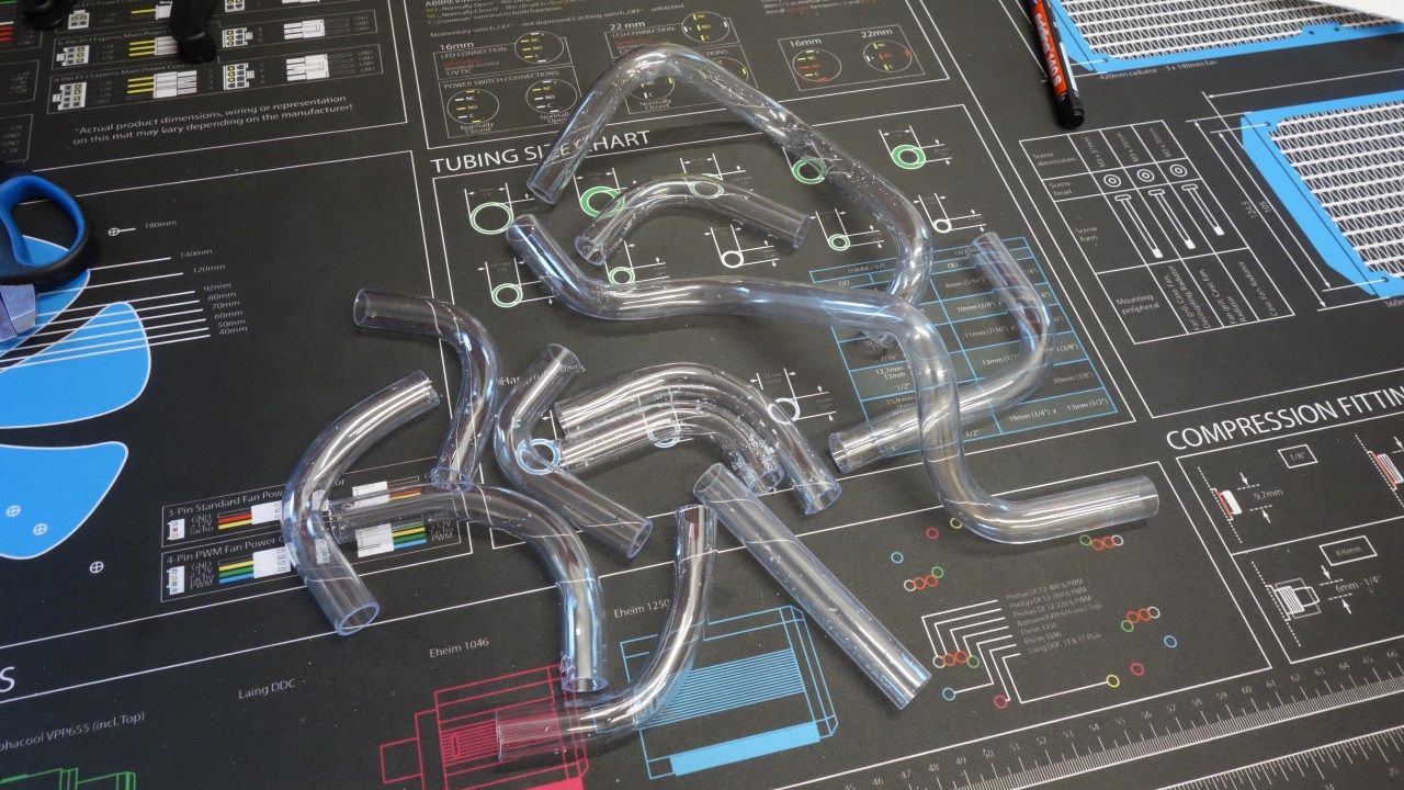
One of my pipes has three bends, that's really hard to do.

I'm not completely satisfied with the result either. 1-2 more attempts and it would have been better, but I simply ran out of tube material. Now it stays like this for now.
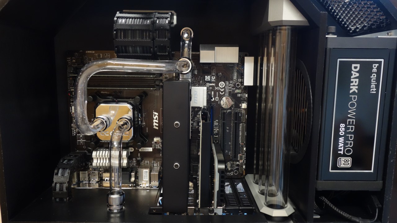

At this point I must apologize for the brevity of my doc. Below you can see the functionally assembled, internally fully wired intermediate state, ready to be submerged and installed in the desk. Along the way, due to time constraints, I have now omitted many small steps and details, especially since I am still missing the photos. Because of my short time I concentrated completely on the completion. Currently something is still missing on the internal lighting, then I'll get all the detail photos including explanations.

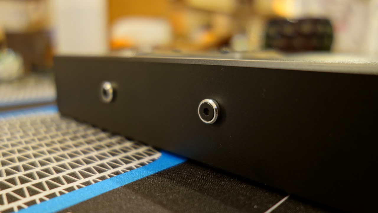
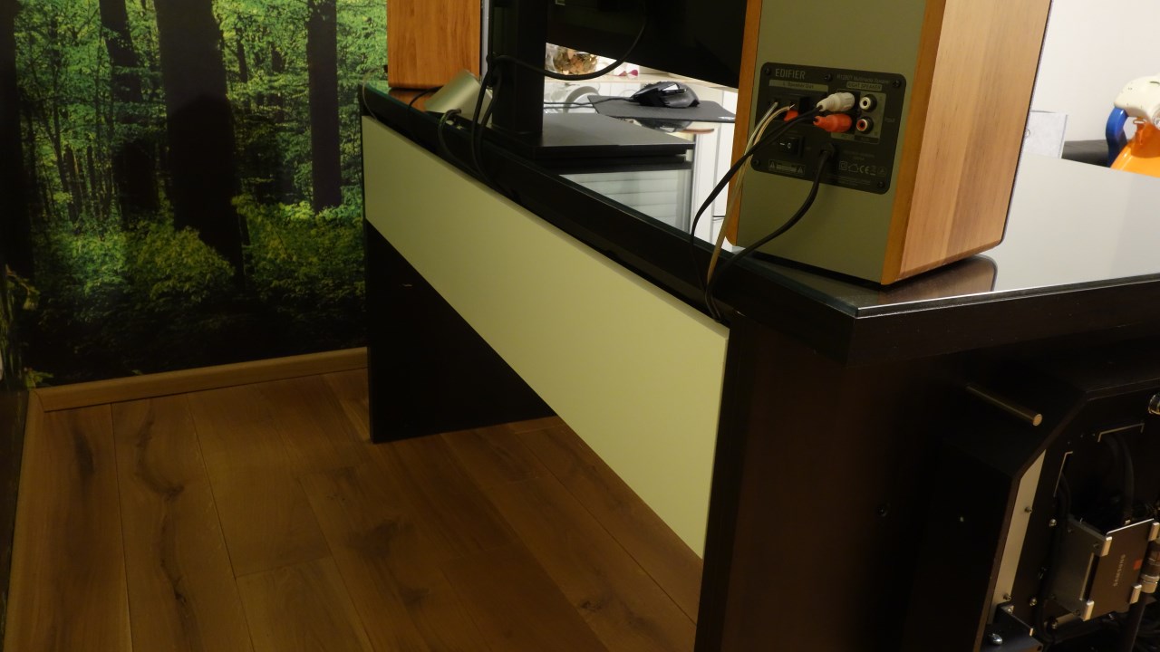
The next step was then to fill it with water. This was a tricky one, with quite a few things going wrong. The following picture shows my filler neck. I discarded filling via the AGB, it's too hard to access.

So I dumped water in there and forgot that a plug was not screwed to the AGB. Was careless, the system overflowed and, due to the location, the water ran nicely from the overflowing AGB through the beautiful power supply. Certainly 200 ml. My mood you can imagine. At least there was no power on it. So I removed the power supply and put it in front of a fan heater for 2 days. As long as I continued with the old power supply. After the 2 days drying time I checked every single wire of the power supply, everything seemed to be ok.
With the AGB sealed, the filling actually went quite well. The problem from the first tests 2 years ago with air in the pump no longer occurs, but I had already put a vent hole in the pump head for emergencies. At the bottom of the Radis I have a ball valve for draining, which I opened (with the drain hose attached), then the system ran cleanly full. Run the pump briefly, refill, repeat 2-3 times, and the system was well filled with just under 2.5 liters.
Initially, the venting did not work so well. I had moved the inlet at the AGB to the top 2 years ago for deaeration reasons (bubble trap), so the water fell as a free stream into the AGB. This brought more bubbles into the system than out. Also caused a loud splashing sound. So I changed that back. I also put another stopcock in the hose underneath the filler neck. This allows me to prevent air from flowing back into the punch. With these two measures, the venting is quite simple and actually runs by itself. I can simply pull the two Radis from the holder during operation and shake them. Only in the hardtube after the filler neck (highest point in the system) is a bubble left behind. Spoiler: After 4 days of operation, however, it also disappeared.
Before the actual commissioning, I still had to finish rebuilding the desk. I exchanged the side panel for my own construction, whereby the new one is offset 10 cm to the inside. Then I carpentered a generous cable channel behind the cross bracing of the table. There is the master-slave-socket and the whole external cable tangle. And that's where the top opening of my side panel runs into. Likewise, the power connection from the base of the side panel does not run directly to the power supply of the PC, but via an intermediate plug to the master-slave socket, where my PC is then plugged in. This is how I preserve my beloved master-slave function.
I purposely didn't post an overall view now, I want to keep that from you guys until I finish the last lighting gimmicks. That won't take 2 more years ;-)
After wiring everything up, the big moment finally came: pressing the power button.
Everything dead, no reaction. Power supply broken? Feverish troubleshooting. After 10 minutes of checking various cables, I realized that my wife had pulled the plug out of the wall to charge her notebook. Plug in, and it runs! Without the slightest problems! What a relief...
The next steps I want to implement in the next few weeks are:
Fine tuning the Aquaero and the monitoring/controls.
soldering the LEDs for AGB and GPU
Manufacturing of the cover for the intermediate plate in the main room
Manufacturing of the bracket for the swiveling floor
With this, the PC is finished except for the fairing. This will take longer, but I'm already working on the exact manufacturing concept in CAD.
Hope you have not yet lost patience with me!

As you can see, I also built a better stand on casters to move the system comfortably and safely. Especially when installing the cables and hardware a big advantage.

The bending needs to be practiced. I'm definitely not a natural at it, and I've produced a fair amount of scrap.

One of my pipes has three bends, that's really hard to do.

I'm not completely satisfied with the result either. 1-2 more attempts and it would have been better, but I simply ran out of tube material. Now it stays like this for now.


At this point I must apologize for the brevity of my doc. Below you can see the functionally assembled, internally fully wired intermediate state, ready to be submerged and installed in the desk. Along the way, due to time constraints, I have now omitted many small steps and details, especially since I am still missing the photos. Because of my short time I concentrated completely on the completion. Currently something is still missing on the internal lighting, then I'll get all the detail photos including explanations.

The next step was then to fill it with water. This was a tricky one, with quite a few things going wrong. The following picture shows my filler neck. I discarded filling via the AGB, it's too hard to access.

So I dumped water in there and forgot that a plug was not screwed to the AGB. Was careless, the system overflowed and, due to the location, the water ran nicely from the overflowing AGB through the beautiful power supply. Certainly 200 ml. My mood you can imagine. At least there was no power on it. So I removed the power supply and put it in front of a fan heater for 2 days. As long as I continued with the old power supply. After the 2 days drying time I checked every single wire of the power supply, everything seemed to be ok.
With the AGB sealed, the filling actually went quite well. The problem from the first tests 2 years ago with air in the pump no longer occurs, but I had already put a vent hole in the pump head for emergencies. At the bottom of the Radis I have a ball valve for draining, which I opened (with the drain hose attached), then the system ran cleanly full. Run the pump briefly, refill, repeat 2-3 times, and the system was well filled with just under 2.5 liters.
Initially, the venting did not work so well. I had moved the inlet at the AGB to the top 2 years ago for deaeration reasons (bubble trap), so the water fell as a free stream into the AGB. This brought more bubbles into the system than out. Also caused a loud splashing sound. So I changed that back. I also put another stopcock in the hose underneath the filler neck. This allows me to prevent air from flowing back into the punch. With these two measures, the venting is quite simple and actually runs by itself. I can simply pull the two Radis from the holder during operation and shake them. Only in the hardtube after the filler neck (highest point in the system) is a bubble left behind. Spoiler: After 4 days of operation, however, it also disappeared.
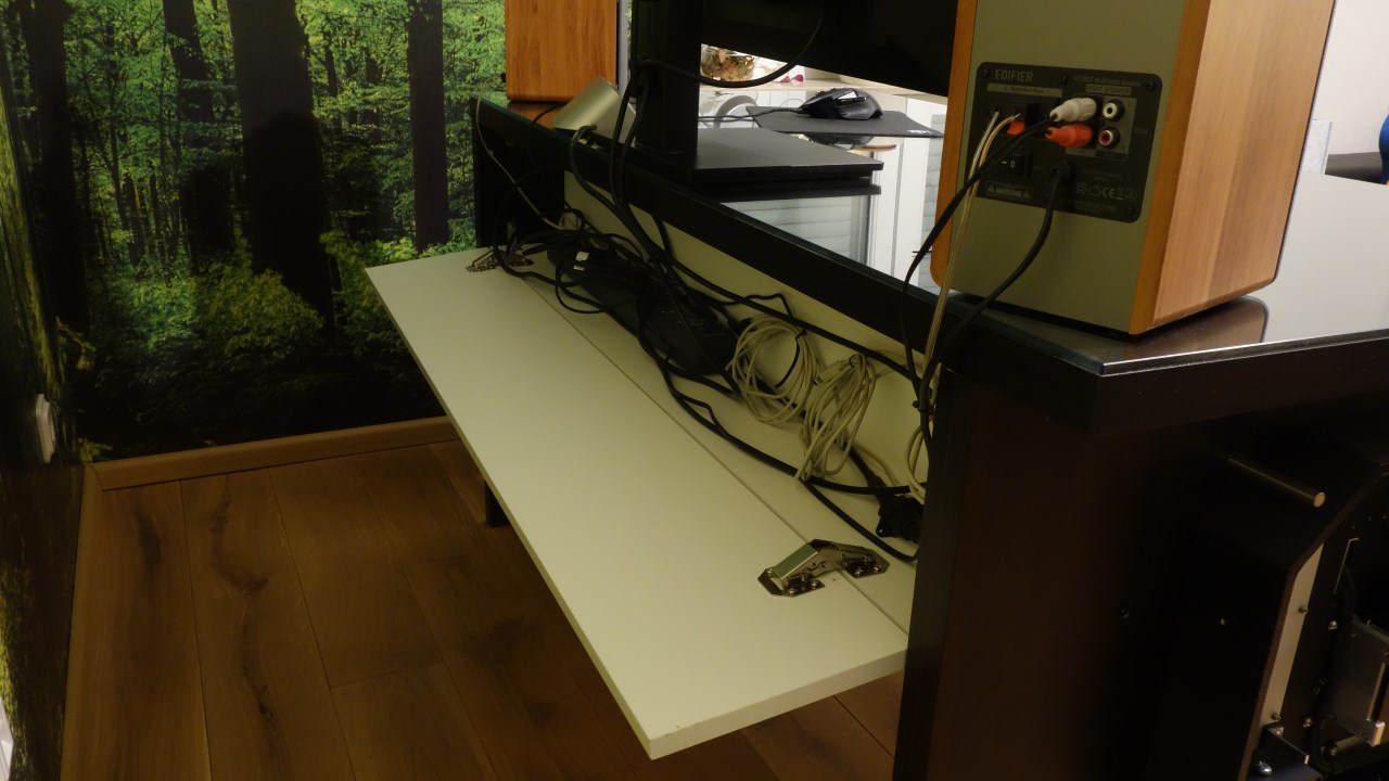
Before the actual commissioning, I still had to finish rebuilding the desk. I exchanged the side panel for my own construction, whereby the new one is offset 10 cm to the inside. Then I carpentered a generous cable channel behind the cross bracing of the table. There is the master-slave-socket and the whole external cable tangle. And that's where the top opening of my side panel runs into. Likewise, the power connection from the base of the side panel does not run directly to the power supply of the PC, but via an intermediate plug to the master-slave socket, where my PC is then plugged in. This is how I preserve my beloved master-slave function.


I purposely didn't post an overall view now, I want to keep that from you guys until I finish the last lighting gimmicks. That won't take 2 more years ;-)
After wiring everything up, the big moment finally came: pressing the power button.
Everything dead, no reaction. Power supply broken? Feverish troubleshooting. After 10 minutes of checking various cables, I realized that my wife had pulled the plug out of the wall to charge her notebook. Plug in, and it runs! Without the slightest problems! What a relief...
The next steps I want to implement in the next few weeks are:
Fine tuning the Aquaero and the monitoring/controls.
soldering the LEDs for AGB and GPU
Manufacturing of the cover for the intermediate plate in the main room
Manufacturing of the bracket for the swiveling floor
With this, the PC is finished except for the fairing. This will take longer, but I'm already working on the exact manufacturing concept in CAD.
Hope you have not yet lost patience with me!
[FONT="]So, the monitoring and control by the Aquaero is done.[/FONT]
[FONT="] [/FONT]
[FONT="]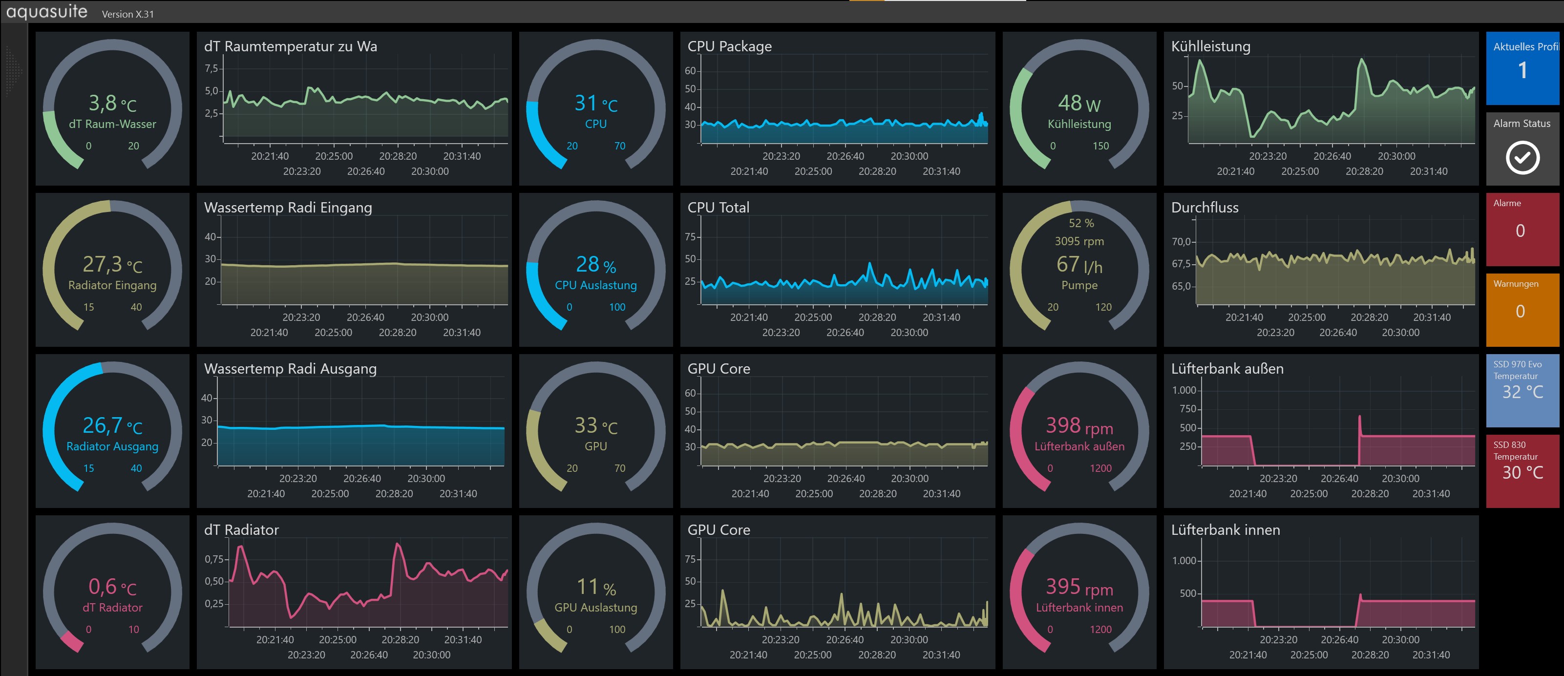 [/FONT]
[FONT="] [/FONT]
[FONT="]The cooling capacity is sufficient for office use or internet surfing for a completely passive operation. The fans then start up with 400 RPM from 28° C onwards. Thus, they are still absolutely inaudible. The only noise that the computer produces is a very, very quiet whirring of the pump. But you have to kneel next to it for that. So the decoupling of the pump also works as planned. I let the pump run at 3000 RPM.[/FONT]
[FONT="] [/FONT]
[FONT="]After about 30 minutes of full load with Prime95 and Furmark, I achieve the following values:[/FONT]
[FONT="] [/FONT]
[FONT="]Radi input water temperature: 33.1° C[/FONT]
[FONT="]Radi output water temperature: 31° C[/FONT]
[FONT="]Temperature delta between radis: 2.1° C[/FONT]
[FONT="]Temperature delta water to room air: 8.1° C[/FONT]
[FONT="]Temperature CPU: 46° C[/FONT]
[FONT="]Temperature GPU: 50° C[/FONT]
[FONT="]Flow rate: 69 l/h [/FONT]
[FONT="]Fan speed: 400 RPM[/FONT]
[FONT="] [/FONT]
[FONT="]I haven't overclocked anything yet, let's see if (and when) I will do that. [/FONT]
[FONT="] [/FONT]
[FONT="]The other ToDos are already in work, updates will follow.[/FONT]
[FONT="] [/FONT]
[FONT="]
 [/FONT]
[FONT="] [/FONT]
[FONT="]The cooling capacity is sufficient for office use or internet surfing for a completely passive operation. The fans then start up with 400 RPM from 28° C onwards. Thus, they are still absolutely inaudible. The only noise that the computer produces is a very, very quiet whirring of the pump. But you have to kneel next to it for that. So the decoupling of the pump also works as planned. I let the pump run at 3000 RPM.[/FONT]
[FONT="] [/FONT]
[FONT="]After about 30 minutes of full load with Prime95 and Furmark, I achieve the following values:[/FONT]
[FONT="] [/FONT]
[FONT="]Radi input water temperature: 33.1° C[/FONT]
[FONT="]Radi output water temperature: 31° C[/FONT]
[FONT="]Temperature delta between radis: 2.1° C[/FONT]
[FONT="]Temperature delta water to room air: 8.1° C[/FONT]
[FONT="]Temperature CPU: 46° C[/FONT]
[FONT="]Temperature GPU: 50° C[/FONT]
[FONT="]Flow rate: 69 l/h [/FONT]
[FONT="]Fan speed: 400 RPM[/FONT]
[FONT="] [/FONT]
[FONT="]I haven't overclocked anything yet, let's see if (and when) I will do that. [/FONT]
[FONT="] [/FONT]
[FONT="]The other ToDos are already in work, updates will follow.[/FONT]
Similar threads
- Replies
- 2
- Views
- 191
- Replies
- 16
- Views
- 1K