CaseLabs STH10

Nope, not really, the outside fans both blow inward and the top fans suck the air out of the top chamber.

I fired up the top four fans this morning to test the wiring and see how much air they pushed out. With them on full speed, I swear it was making the case lift like a drone taking off :-)
 
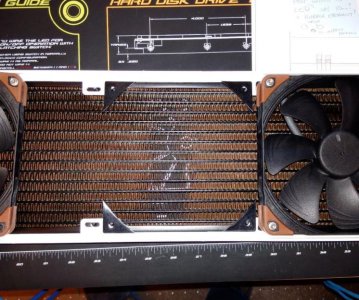
I hope you flushed those rads good. Alphacool rads perform very well, but the crap that comes out of those things is unreal! Looking good Blade Runner!

Thanks, I used the hosepipe on them but thanks for the tip. My plan is to run the loops for a week or so before the mobo gets installed, without the water blocks for the CPU and GPUs attached, changing the water a often as needed until it runs nice and clean.

I also have the 2 Aqua Computer inline filters which have a pretty fine SS gauze which should take care of any little bits that get into the system in the future.
 
I wanted to get the bulkhead fittings drilled and fitted today so lots of measuring and re-measuring of the GPU water block outlet/ inlet and finding the centre line of the CPU in relation to the PCI plate today.

The bulkhead fittings are actually Fill Ports but they work. The light port Monsoon rotarys have the wrong coloured caps for the LEDs, I am waiting on a few more black fittings.

The 2 valves in this chamber along with 4 more in the pedestal will allow me to remove the motherboard assembly on the slide out back plate without draining the whole system.
 

Attachments

  • BulkheadFittingsBelow.JPG
    BulkheadFittingsBelow.JPG
    50.6 KB · Views: 75
  • BulkheadFittingsTop.JPG
    BulkheadFittingsTop.JPG
    64.8 KB · Views: 75
  • LightPortValveTempSensorTop.JPG
    LightPortValveTempSensorTop.JPG
    92.5 KB · Views: 74
  • TempSensorsTopChamber.jpg
    TempSensorsTopChamber.jpg
    89.7 KB · Views: 73
Got the tricky offset bend around the rear rad made and fitted tonight.

I did not want to do it in fittings if I could help it, and it took two attempts but I am pleased with the result.

Note that all of the fittings in the middle of the rads will be black, the two white 90 degree rotarys on the radiator inlets are just temporary to allow measurement of the pipes.
 

Attachments

  • OffsetRadReturnPipe.JPG
    OffsetRadReturnPipe.JPG
    60.1 KB · Views: 71
  • TheCure....JPG
    TheCure....JPG
    86.5 KB · Views: 79
  • 100mmCut.JPG
    100mmCut.JPG
    93.1 KB · Views: 79
  • FirstAttempt.JPG
    FirstAttempt.JPG
    88.7 KB · Views: 72
  • MonsoonTools.JPG
    MonsoonTools.JPG
    92.5 KB · Views: 74
I got the last of the pipework bent and fitted in the top chamber tonight and I will now be able to work out the best place for the 2 fan splitter hubs.

The only thing that I did not like about the case when it was delivered was the feet. They looked just like the round rubber door stops you see screwed into the floor.

A quick search and I found the MNPC tech grooved alloy and rubber which will look a lot better than the standard ones.
 

Attachments

  • TopChamberAllPipedUp3.JPG
    TopChamberAllPipedUp3.JPG
    61.8 KB · Views: 72
  • TopChamberAllPipedUp2.JPG
    TopChamberAllPipedUp2.JPG
    69.6 KB · Views: 73
  • TopChamberAllPipedUp4.JPG
    TopChamberAllPipedUp4.JPG
    70.1 KB · Views: 76
  • MNPC_Feet.JPG
    MNPC_Feet.JPG
    71.2 KB · Views: 74
  • DoorStops.JPG
    DoorStops.JPG
    37.3 KB · Views: 73
Last edited:
Arrrrrrrrrrrrrrrrrrrrrghhhhhhh, :mad: 
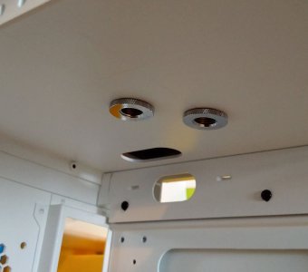
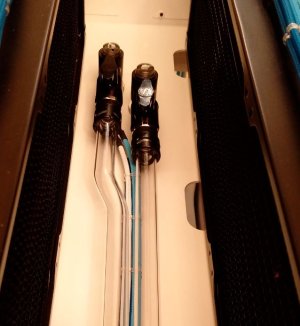
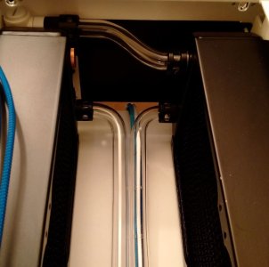
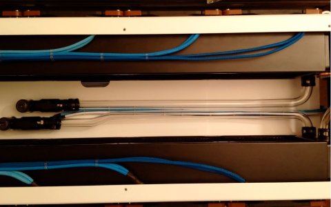
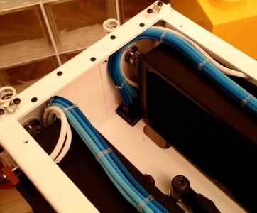
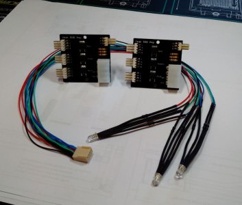
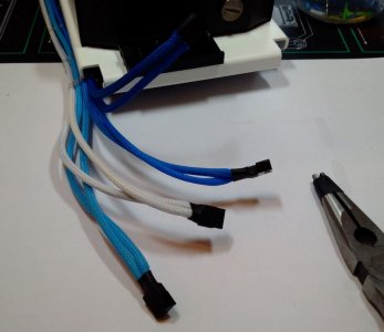
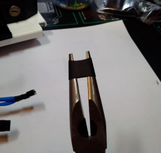
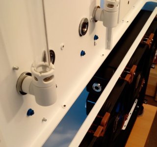
crimping terminals on to fan wire is not my idea of fun but its done now, :p well the top 12 radiators anyway and the splitters have a home tucked away behind the rads.
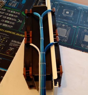
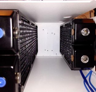
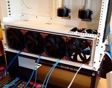
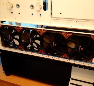
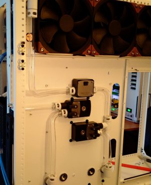
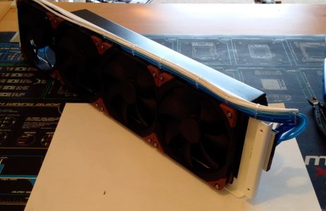
I said I had finished the pipework in the top chamber but I had forgotten about the fill ports.

This would not have been possible without the awesome Bitspower Aquapipe adjustable length fittings.

These allowed me to get a fitting screwed between the two fixed points of the radiator bleed point and the bulkhead fitting on the rear of the case.
 

Attachments

  • FanWiringTopFrontRad.jpg
    FanWiringTopFrontRad.jpg
    78.7 KB · Views: 72
  • FillPortRearRadOutlet.JPG
    FillPortRearRadOutlet.JPG
    41.6 KB · Views: 71
  • FillPortRearRad.JPG
    FillPortRearRad.JPG
    44.9 KB · Views: 67
  • FanWiringTopChamberAllDone.......JPG
    FanWiringTopChamberAllDone.......JPG
    82 KB · Views: 71
Last edited:
Working from the top down the next job is fixing the reservoirs and filters.

I used the CAD full scale paper template I made a few weeks ago to locate and then centre punch the holes. (The reservoirs are deliberately off centre to the left so that they are both seen better through the window of the case).

I have a Dremel and I could have used it in this location but I find it too harsh and very hard to control properly for fine work. (The rear of these cut outs is in full view with no cover-plate, unlike the front, so they need to be neat). A row of holes, a hacksaw blade and a file does a much better job IMHO.

The lower filter is in place loose, I don't want to drill the final fixing holes until the other filter is in place so that I can get them perfectly aligned with a couple of straight edges.
 

Attachments

  • LowerAQ_FilterTrialFit.JPG
    LowerAQ_FilterTrialFit.JPG
    30.1 KB · Views: 76
  • 20MinFiling.JPG
    20MinFiling.JPG
    44.9 KB · Views: 76
  • RoughOut.JPG
    RoughOut.JPG
    46.4 KB · Views: 68
  • Drilled.JPG
    Drilled.JPG
    33.4 KB · Views: 65
  • PilotHoles.JPG
    PilotHoles.JPG
    35 KB · Views: 72
  • CentrePunchedResMounts.JPG
    CentrePunchedResMounts.JPG
    77 KB · Views: 71
  • ResTemplateInPlace.JPG
    ResTemplateInPlace.JPG
    67.2 KB · Views: 70
Last edited:
Reservoirs and filters both trial fitted.
 

Attachments

  • PipedOutBack.JPG
    PipedOutBack.JPG
    58.2 KB · Views: 107
  • RearOfRes_Filter.JPG
    RearOfRes_Filter.JPG
    50.5 KB · Views: 108
  • FiltersInPlace.JPG
    FiltersInPlace.JPG
    46.6 KB · Views: 105
  • BothResInPlace.JPG
    BothResInPlace.JPG
    59.7 KB · Views: 103
Last edited:
Three pipes bent and fitted this evening.

Plenty more to go :eek:
 

Attachments

  • BendingBoard.jpg
    BendingBoard.jpg
    76.3 KB · Views: 98
  • UVCure.JPG
    UVCure.JPG
    84.1 KB · Views: 95
  • TightSqueeze.JPG
    TightSqueeze.JPG
    62.9 KB · Views: 104
  • Curvy.JPG
    Curvy.JPG
    69.2 KB · Views: 105
  • FiltersPartPlumbed.JPG
    FiltersPartPlumbed.JPG
    59.6 KB · Views: 98
Last edited:
I had to use the Dremel to grind down the threaded socket to allow the fitting of one of the flow meters. Double sided tape by 3M is as good as screws and also isolates the unit from the case.
 

Attachments

  • FlowOutletPipe.JPG
    FlowOutletPipe.JPG
    64.2 KB · Views: 104
  • 3M_DoubleSidedTape.JPG
    3M_DoubleSidedTape.JPG
    59.8 KB · Views: 106
  • GrindOff.JPG
    GrindOff.JPG
    34.6 KB · Views: 110
  • TopRadiatorsToReservoirOutlets.JPG
    TopRadiatorsToReservoirOutlets.JPG
    84.8 KB · Views: 115
Last edited:
I had a delivery from Germany today, the Jeak AMPs and RGB LEDs to fit them. Jannik who makes them is very talented with the soldering iron.

The Aqueros will light up only one RGB LED as standard and the Farbwerks are for RGB strips. I wanted several RGB LEDs to allow both loops to be illuminated depending on their temperatures and the Jeak amps will allow that.
 

Attachments

  • Jeak_RGB_Amp_RGB_LEDs.JPG
    Jeak_RGB_Amp_RGB_LEDs.JPG
    77.6 KB · Views: 104
I had to trial fit the lower radiators and fans to check where the pipes from above will go. So far so good,it all seems to work pretty much as planned.

I have managed to forget to buy two fans for the rear 280 rad to act in push but they can be fitted later when they turn up.

The drop in side mounts are much easier to work with in this chamber as they have clearance around them. I have been able to fit the rads to the fans on my desk which is much easier than in-situ.

I need to get some shorter matching socket cap head screws to attach the 3 fans that are not screwed into radiators. Then I can use the Phobya corner gaskets so that all the fans are on the same level.
 

Attachments

  • 420x45_280x60_RadsTrialFitOnSideMounts.jpg
    420x45_280x60_RadsTrialFitOnSideMounts.jpg
    77.6 KB · Views: 102
  • LowerFrontRad&FansTrialFit.jpg
    LowerFrontRad&FansTrialFit.jpg
    82.3 KB · Views: 104
  • PhobyaGasketsCutDownFitting.jpg
    PhobyaGasketsCutDownFitting.jpg
    97.5 KB · Views: 106
  • LowerRearRadTrialFit.JPG
    LowerRearRadTrialFit.JPG
    80 KB · Views: 104
  • RouteForPipe.JPG
    RouteForPipe.JPG
    52.8 KB · Views: 102
  • LowerRearFansRadTrialFit.JPG
    LowerRearFansRadTrialFit.JPG
    88.9 KB · Views: 105
  • LowerRearFansOnDropInMount.jpg
    LowerRearFansOnDropInMount.jpg
    98.1 KB · Views: 108
Nice one! :D ... now that is a shit ton of noctua fans in one rig lol!

It was not planned this way! I was going to have 8 at the start but it sort of grew..........and grew.........and grew, especially since the pedestal was added. I count 24 x 140mm's and 2 x 120mm's now :huh:, ouch!


Coming together nicely!

Thank you.


Another lot of fan wire crimping done this morning, I hate fan wires, my fingers are too big and my eyesight too bad; working through a magnifier is a pain.
 

Attachments

  • FanSplitter2.JPG
    FanSplitter2.JPG
    64.5 KB · Views: 95
  • StrechHeatShrink.JPG
    StrechHeatShrink.JPG
    52.5 KB · Views: 95
  • FanSplitter3.jpg
    FanSplitter3.jpg
    76.3 KB · Views: 101
  • FanRadAssembly2.JPG
    FanRadAssembly2.JPG
    69.9 KB · Views: 99
  • PushPull.JPG
    PushPull.JPG
    89.7 KB · Views: 93
Last edited:
It was not planned this way! I was going to have 8 at the start but it sort of grew..........and grew.........and grew, especially since the pedestal was added. I count 24 x 140mm's and 2 x 120mm's now :huh:, ouch!
.

Fuck... sake... dude :mellow:.... 24 x 140's, what didn't all of that cost you haha? :lol:
 
Back
Top