Permafrost
Compo Whore
Rejoice, curse and/or cry.
[/list]
hahaha i really look forward to seeing this and might even get a cheap psu just to play with

Rejoice, curse and/or cry.
[/list]
Yeah this PSU wasn't very expensive, so if I screw up colossally I won't lose that much money
(although quite a bit of time, but of that I have quite a bit at the moment).
Besides it's a good practice project for HELIOS.
How did you determine the type of variable resistor you needed for that quantity of fans? I am familiar enough with the math surrounding electronics to get the idea, so feel free to be technical if you like x-).

To be honest I didn't.
I bought a few of those resistors a couple of years ago and just had them laying around.
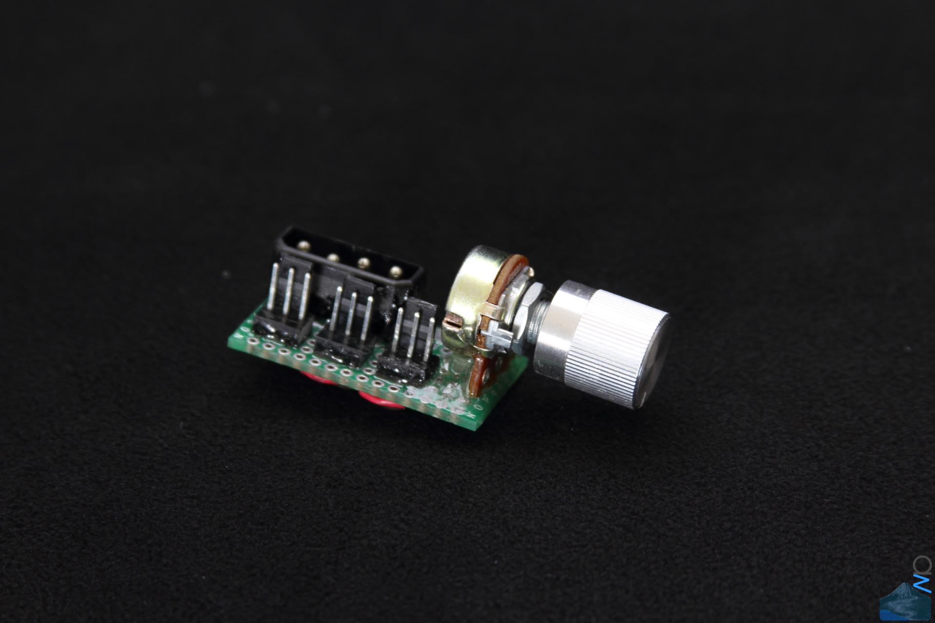
It's this model (100 Ohm), although I didn't buy it from caseking.
I did actually work on this a while back trying to figure out what sort of fixed resistors to use,
but I scrapped that part of that project and changed plans. I might try to do the calculations
nonetheless just out of curiosity and for being thorough.
LOL I love it x-). That tends to pretty much be how all of my projects lately have been turning out; Plug and Pray, as it were x-). Glad all of that worked out for you tho, pretty clean job all things considered. I would imagine that ensuring a parallel circuit makes things significantly easier, assuming that all of the fans you will be using generally have the same specs and resistances to overcome in the circuit.
looking good matey. I'm going to have a try of the cable stitching, I've seen a few vids but all seem to be a different method to your way. Which looks quite simple compared to others. But like you said very laborious.
")
") ), which means I can't make any convoluted
), which means I can't make any convolutedMost fans have some sort of power rating. I think the Akasa ones I had lying around were rated for 100mA at 12V.How did you determine the type of variable resistor you needed for that quantity of fans? I am familiar enough with the math surrounding electronics to get the idea, so feel free to be technical if you like x-).
Nice job on the fan controller!
Most fans have some sort of power rating. I think the Akasa ones I had lying around were rated for 100mA at 12V.
If you simply use Ohms law you get an effective resistance of the fan of 12/0.1 = 120 Ohms. Since the fan is just a DC motor, and all motors rotational speed is a function of the current flowing in them. If you assume a linear relationship between fanspeed and current, halve the current and you'll halve the speed.
To do that, just make your resistor 120 Ohms (same as the fan), for 66% fan speed, make it 80 Ohms etc.
If you do anything in regards to electronics you'll see it again and again, it comes into everything.Figured that was how you could do it. Been so long since I touched on Ohm's Law...
Nice job on the fan controller!
Most fans have some sort of power rating. I think the Akasa ones I had lying around were rated for 100mA at 12V.
If you simply use Ohms law you get an effective resistance of the fan of 12/0.1 = 120 Ohms. Since the fan is just a DC motor, and all motors rotational speed is a function of the current flowing in them. If you assume a linear relationship between fanspeed and current, halve the current and you'll halve the speed.
To do that, just make your resistor 120 Ohms (same as the fan), for 66% fan speed, make it 80 Ohms etc.
If you do anything in regards to electronics you'll see it again and again, it comes into everything.
But yes, all you're doing is just limiting the current that the Fan is pulling with the resistor.
Questions:
Is it possible to construct a 12 fan controller similar to what you built for 3? And, would it be cheaper than purchasing one?
 ), however, Zoot knows this stuff inside out, I'm sure he'll call me out
Nah, no need. What you've said is correct.Zoot knows this stuff inside out, I'm sure he'll call me out
on any BS.
Nah, no need. What you've said is correct.
(no, I wasn't sat with nothing to do before work, honest)Gotta say, I wasn't familiar with cable lacing and I must look into that for my since I hate cable ties with a passion but i'm forced into used them at present. Looking forward to what else you come up with.
FYI - 1174 holes drilled
),