Well as promised here is the start of my log detailing the build of an external water cooling rig. I probably started accumulating the parts for this build about 9 months ago & i've been chomping at the bit trying to find the time to start it.
I actually started the build about a month ago & have tried my best to take pictures along the way. I reckon/hope i'm about 2 weeks away from completion.
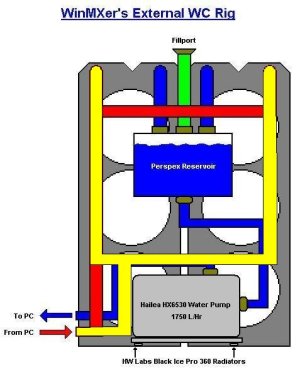
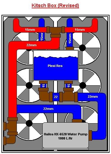
Here is a sketch-up in MS Paint of the basic shape of things.
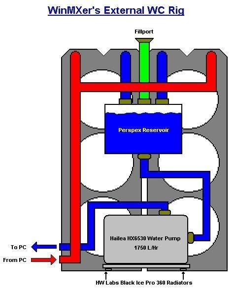
My motivation for building this is to be able to cool 2 PC's with one setup. I currently have a small form PC with no room to accomodate a rad, pump, etc & a tower system waiting to be put together. I love what other people here have done in utilising the space within their cases, so I may try an internal setup at a later stage.
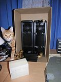
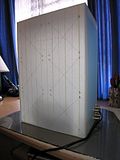
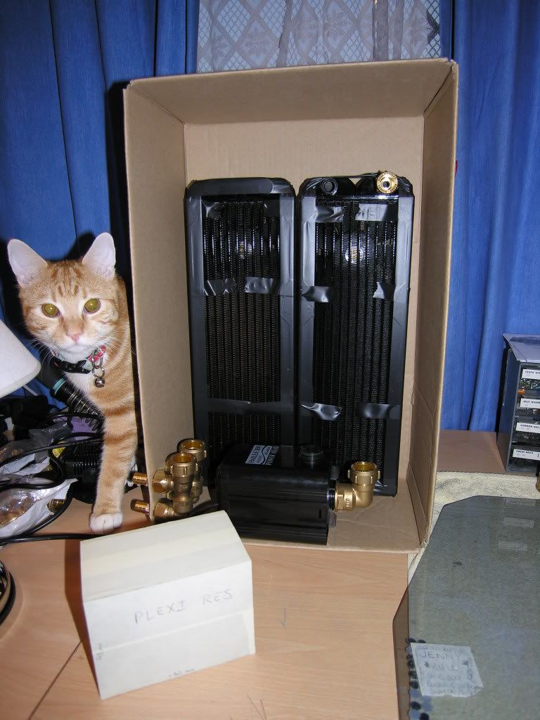
I have built the box already using 5mm thick clear perspex. The front will be detachable, maybe held in place using small magnets for ease of entry. I saw this used on a case in another thread & thought it was a pretty sweet idea. Here's some pics of the starting stage. I used a cardboard box at first to give me a rough idea of dimensions & component placement. The sketch does'nt show it but there will be 2 inlets & 2 outlets, terminated using 1/2" barbs to connect the reinforced plastic tubing. (N.B. cat not included in final build!)


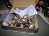
All of the pipe runs in this build will be with standard copper pipe. The connections to the Hailea HX-6530 pump will be with a female 22mm adapter. The rest of the runs will be in 15mm copper pipe. I'm using brass compression fittings to plumb the pipework in. I know I could have used solder fittings but I like the look of the compression fittings, gives it a gritty 'Kitsch' feel. It might also have something to do with having 2 large containers full of brass fittings getting in the way :crazy:

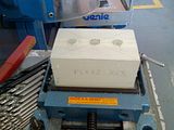
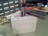
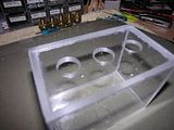
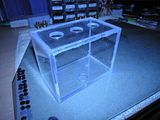
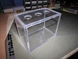
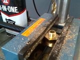
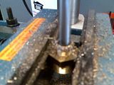
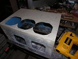
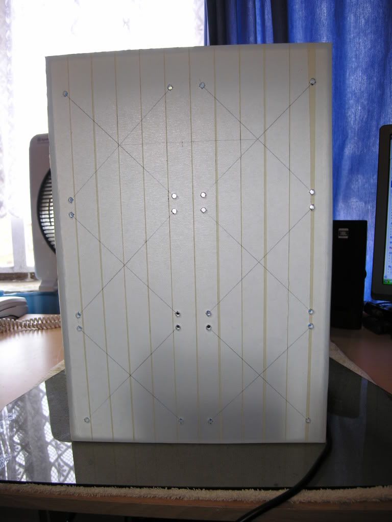
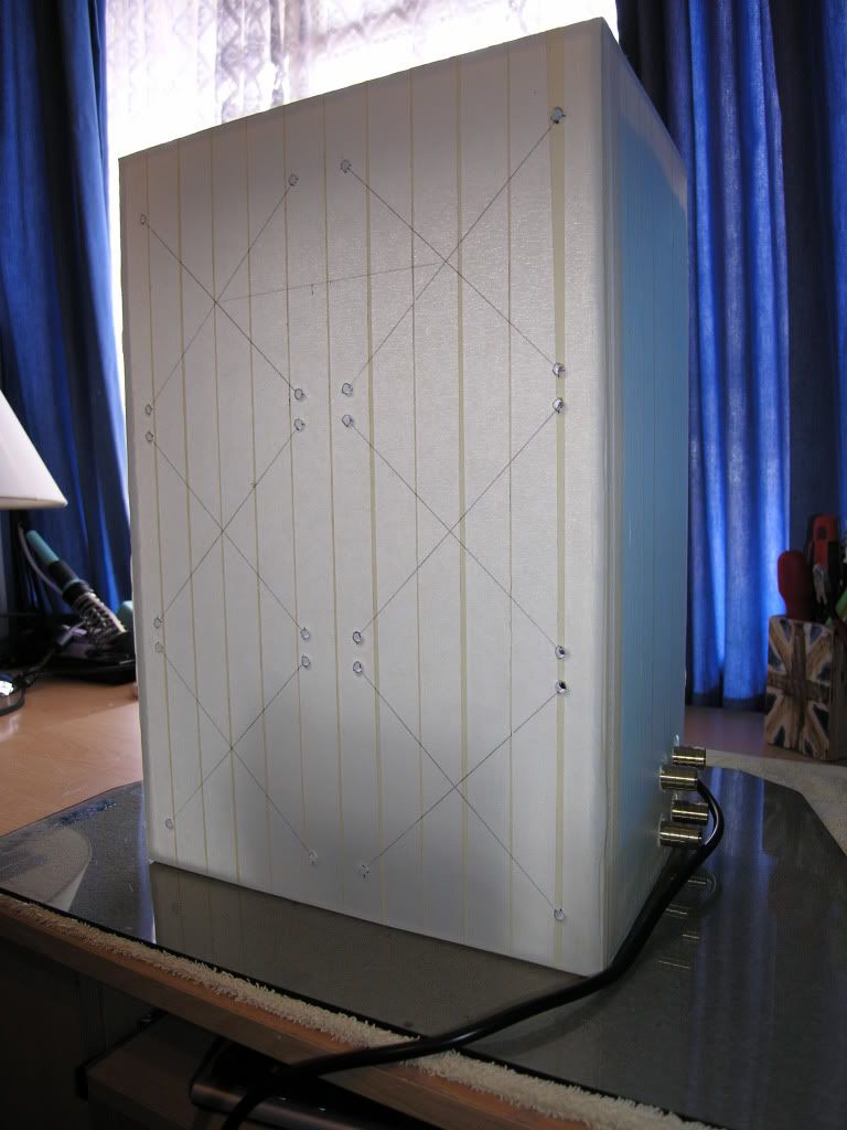
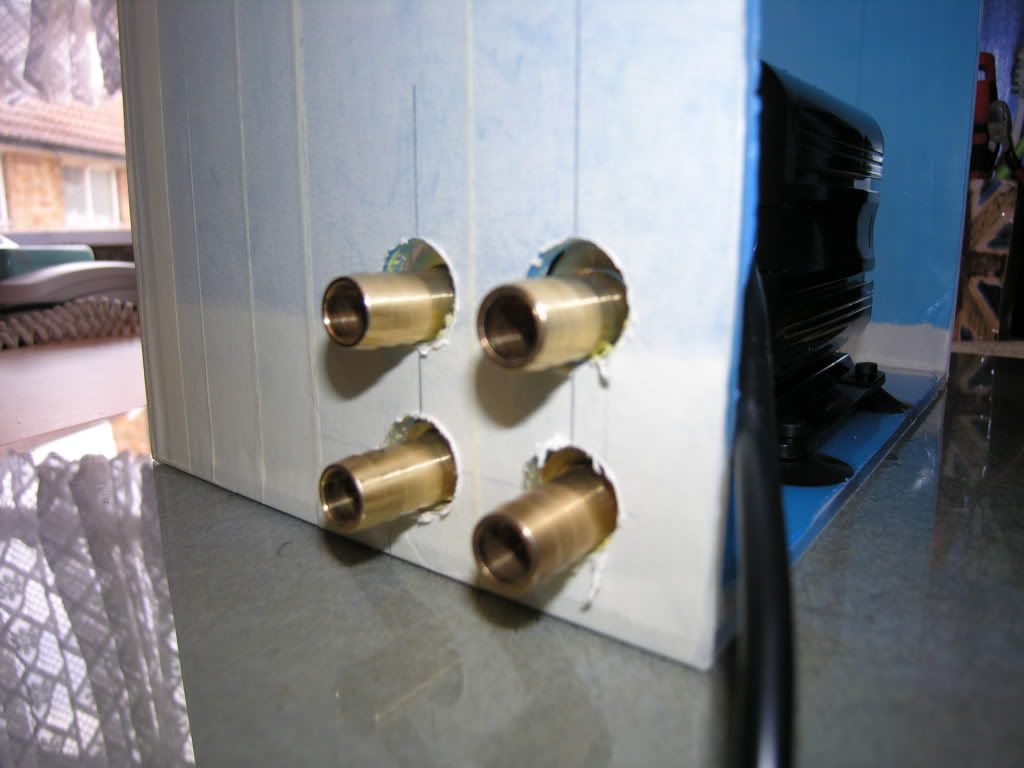
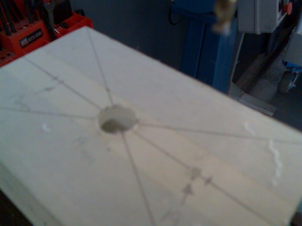
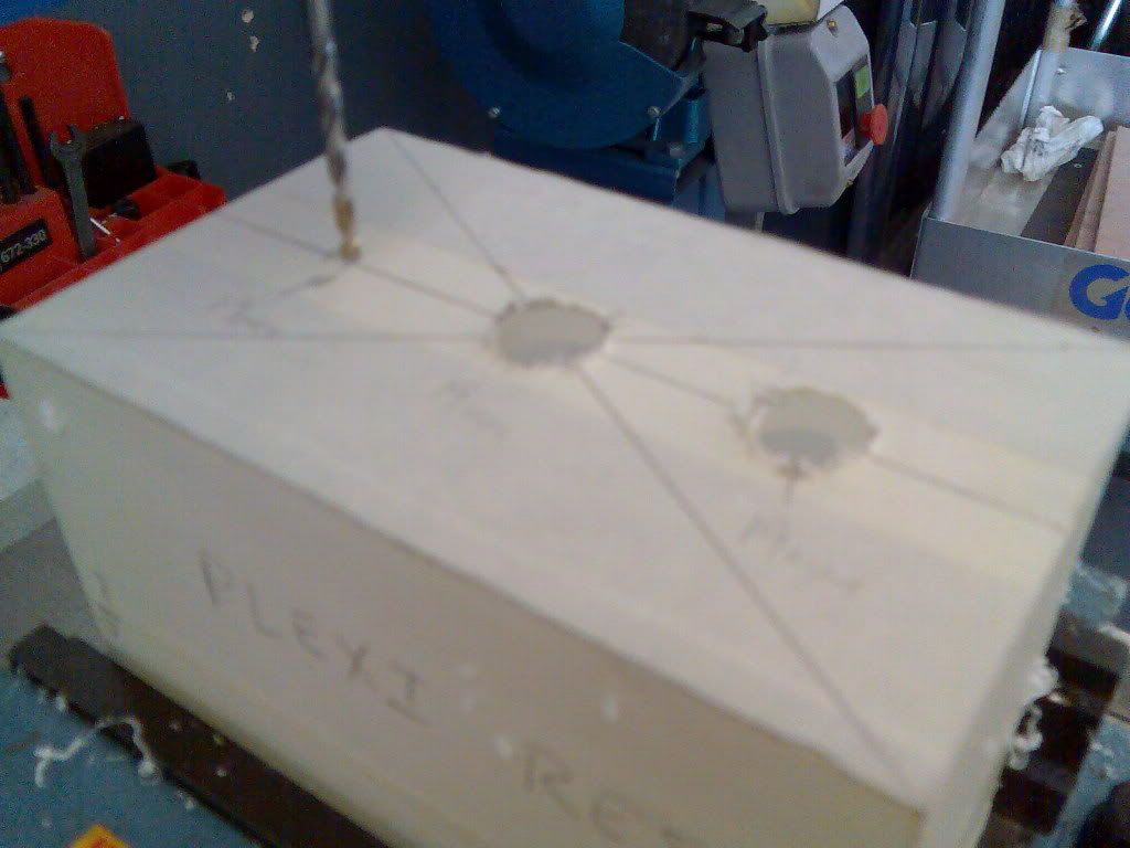
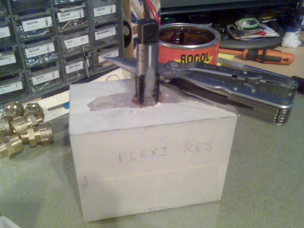
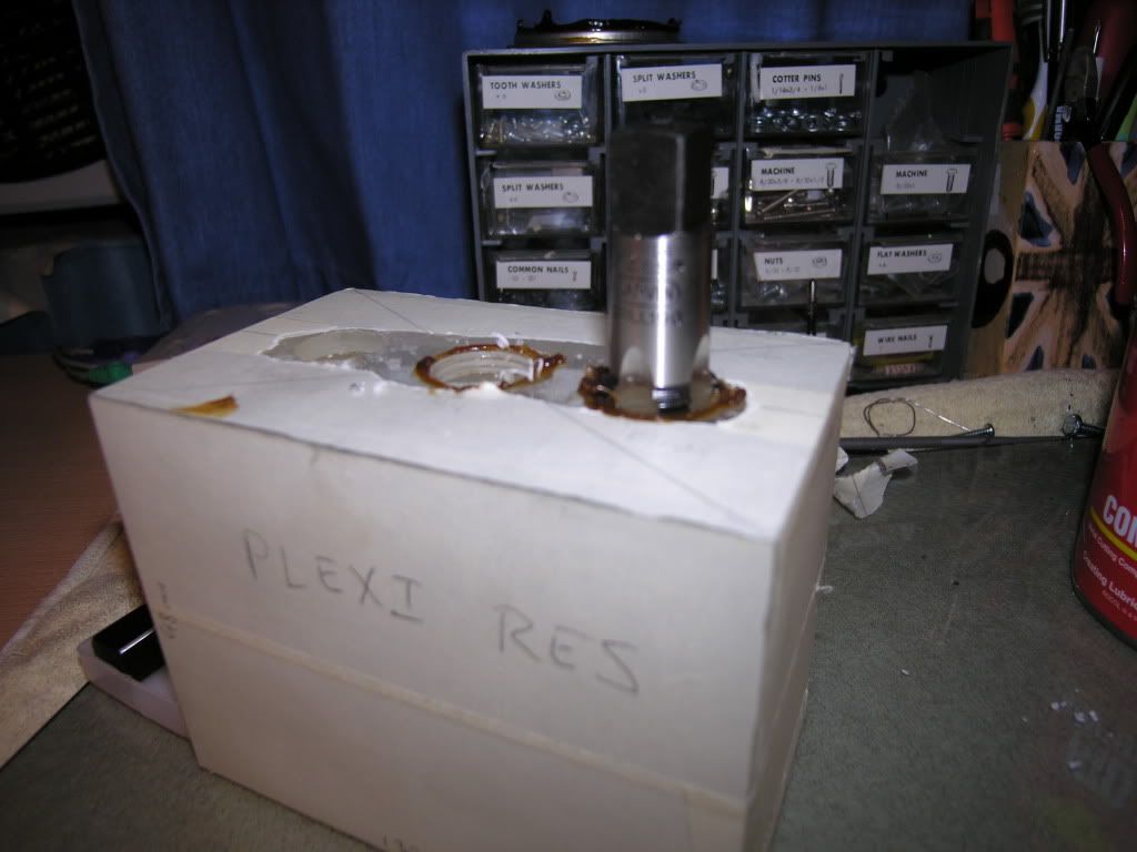
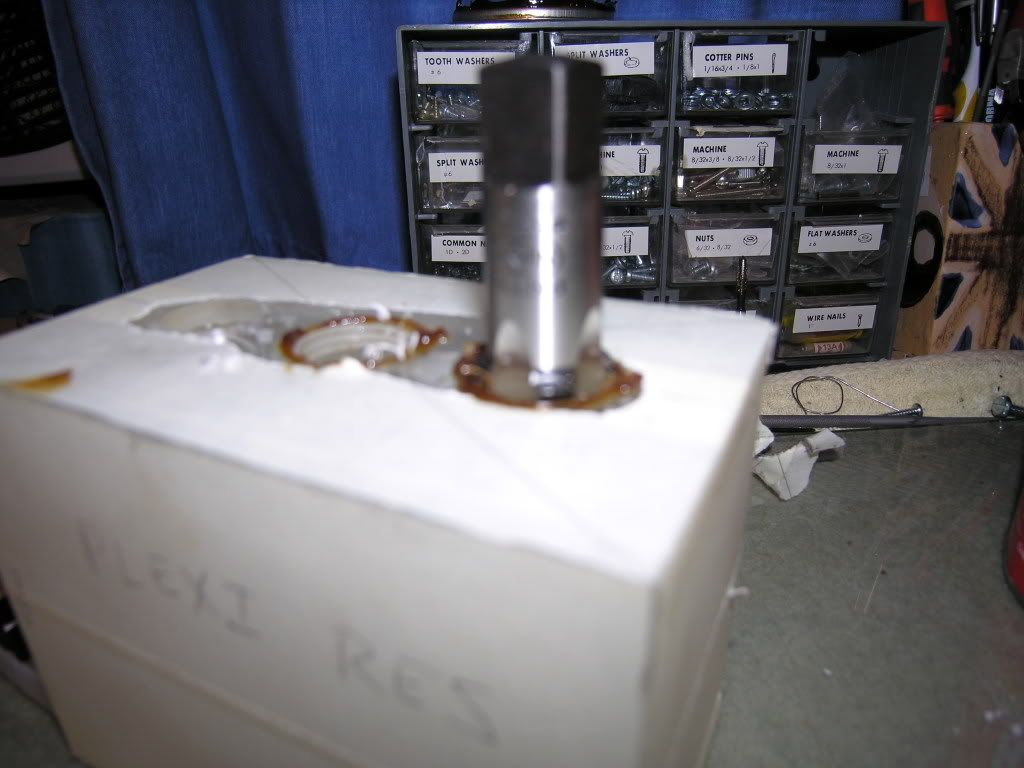
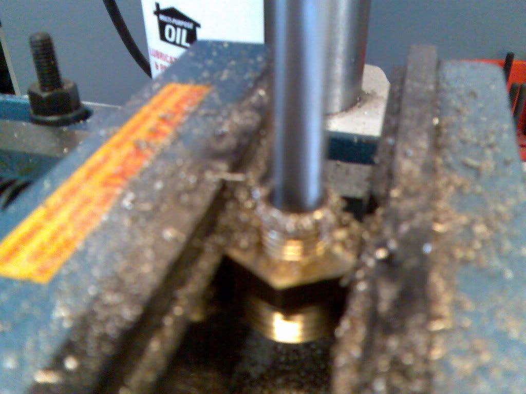
I've also completed the res too. I have made this from the 5mm perspex & it looks really nice. The 4 connections to it are made with 1/2" BSPP to 15mm fittings with O-rings to seal against leaks. The holes for the connections were drilled out to 19mm & tapped to 1/2" BSPP. I picked up a tap set off eBay for only £7.50. The drilling was really time consuming but I did'nt want to rush it & risk cracking the perspex. I started with a 4mm drill increasing the diameter 1mm each time. You should be able to see all the drill bits laid out in the end pic.
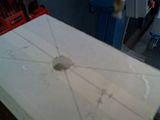

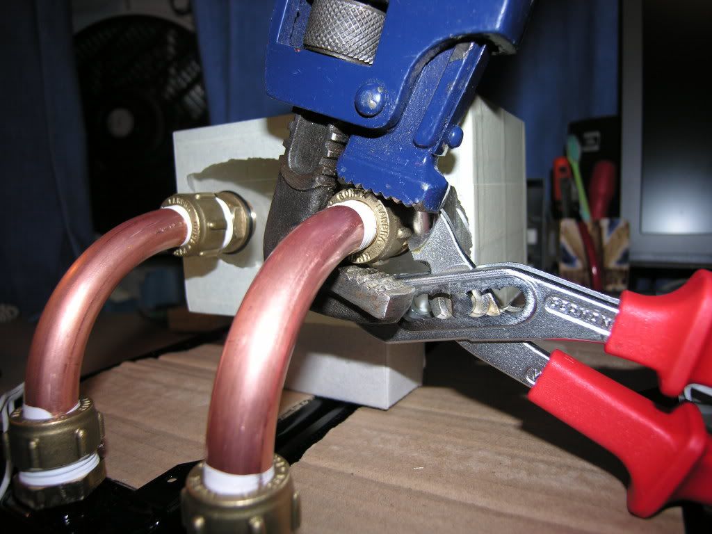
The connections to the res are made with 15mm compression fittings. All threads on the brass fittings are 1/2" BSPP. The holes in the res were drilled out to 19mm, which is the ideal tapping drill size for this thread. I could'nt get the 19mm drill to fit in the pedestal drill's chuck so I had to turn the shaft down to 13mm on the lathe.
To tap the 1/2" BSPP thread I picked up a great set of hand taps off eBay for £7.50. I could'nt find a tap wrench big enough for them, but found a pair of pliers to be adequate for the job.
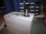
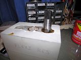
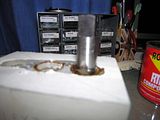
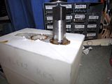
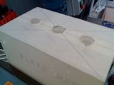
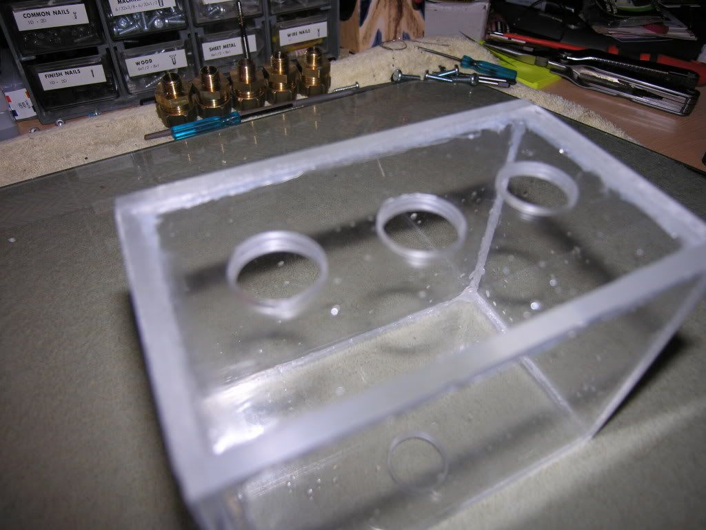
Here's some pics of the tapped res without the masking tape. I got impatient & wanted to see how it looked :drool:
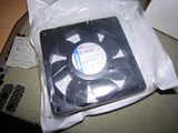
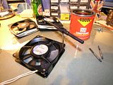
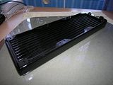
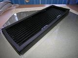
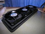
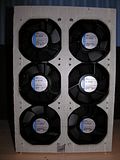
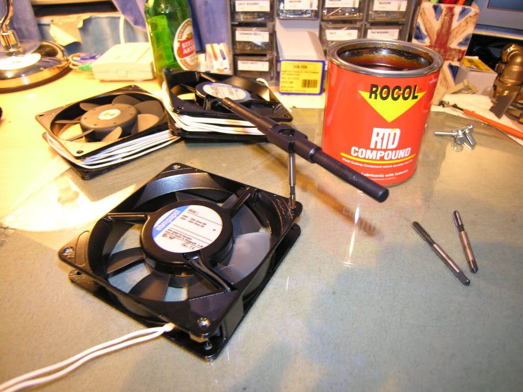
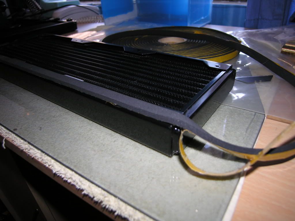
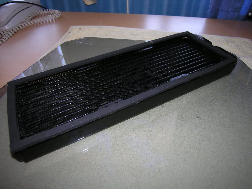
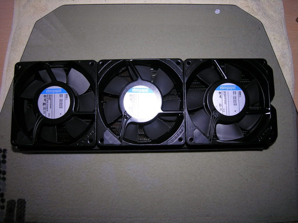
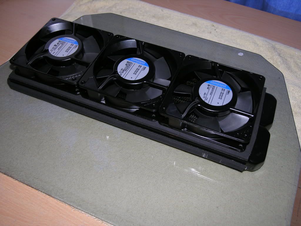
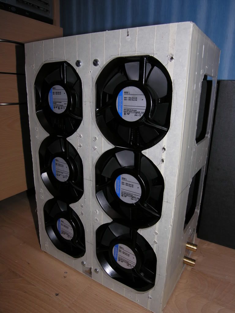
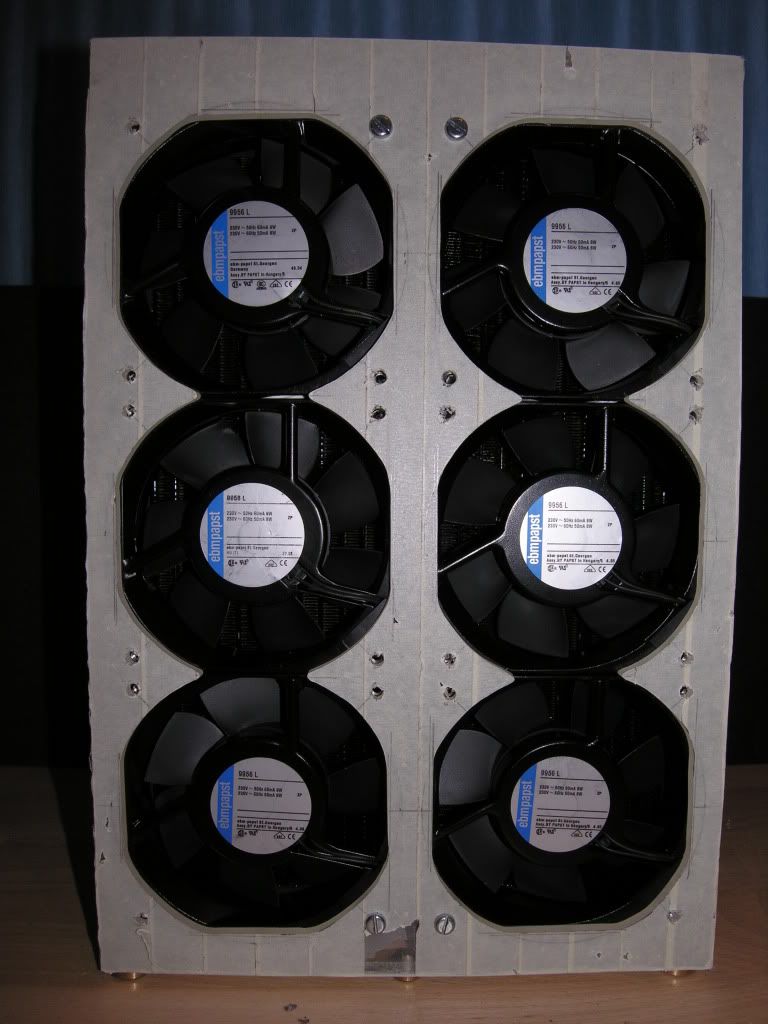
The next step was to mount the six EBM Papst 240v 119mm fans on the rads. I chose to opt for pulling air through mainly to have the fans at the rear. This was to stop them getting directly splashed by water during leak testing & refills. The fans are rated at 29.5dBA, pulling 84m³/h each through the rads. If they prove to be too noisy i'll think about incorporating a fan controller. To allow airflow into the case i'll be affixing six 120mm filtered grates to the sides & top.
Before mounting the fans on the rads, the rear facing mounting holes were tapped to M5 so that the fans could be secured to the perspex case.
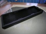
I was fortunate to come across a reel of adhesive backed foam strip to use between the rad & fan edges. This should help prevent suction loss & maybe absorb some vibration.
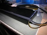
I forgot to take pictures of the cabling & connections to the fans, sorry :nono: . I used 1.5mm single core cable soldered to the pins & shrouded to prevent direct contact. This was then run along the sides of the fans & held in place with clear cable ties.
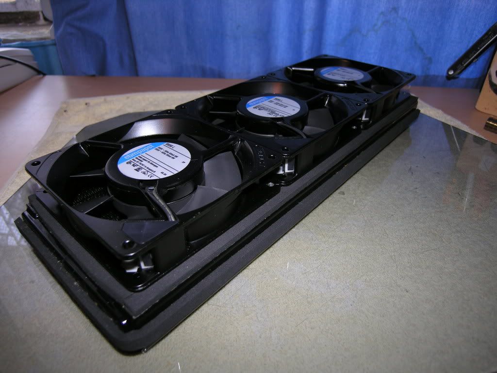
The six fans were then secured in place with 4mm self-tappers on all four corners of each fan.


Whilst I was working on the rads it was a constant niggle that G1/4" was quite a pitiful size for the inlets/outlets. After thinking it through I had two real choices;
1. Tap out the existing threads to 3/8" (max. capable)
2. Use G1/4" fittings but ream them out by a few millimetres.
Looking at the G1/4" to 15mm fittings I had to hand, it was possible to open them up from 8mm ID to 10mm ID, so that's exactly what was done.
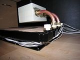
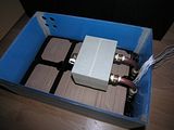
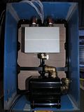
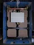
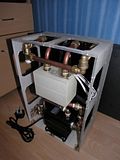
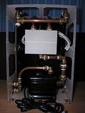
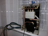
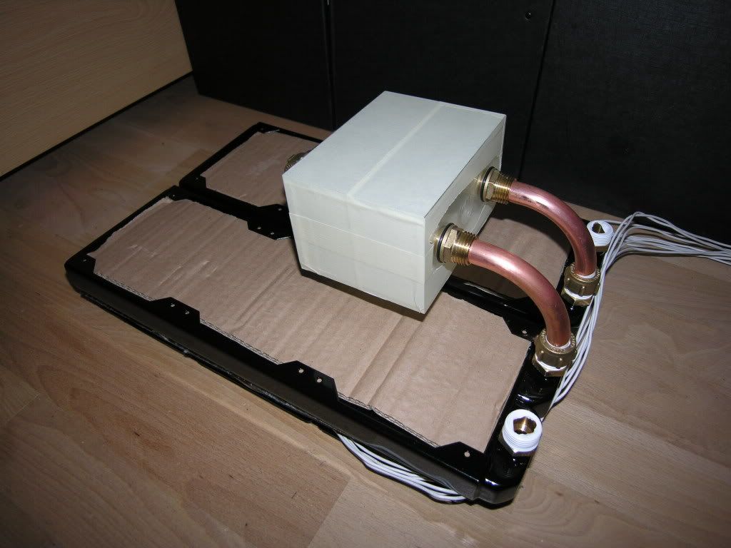
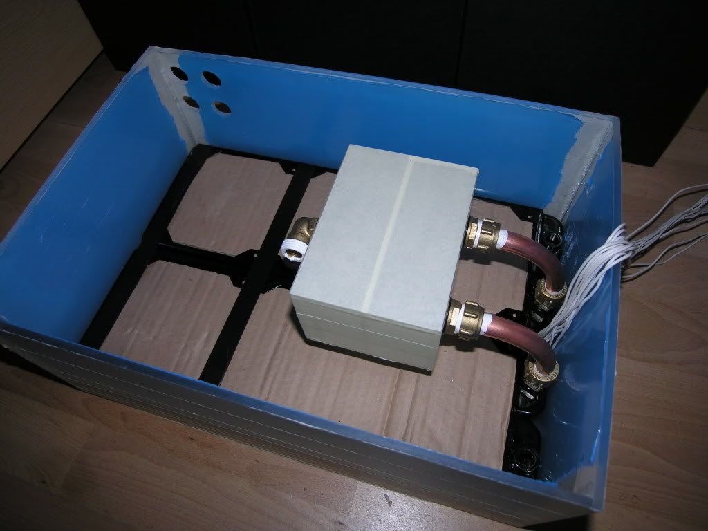
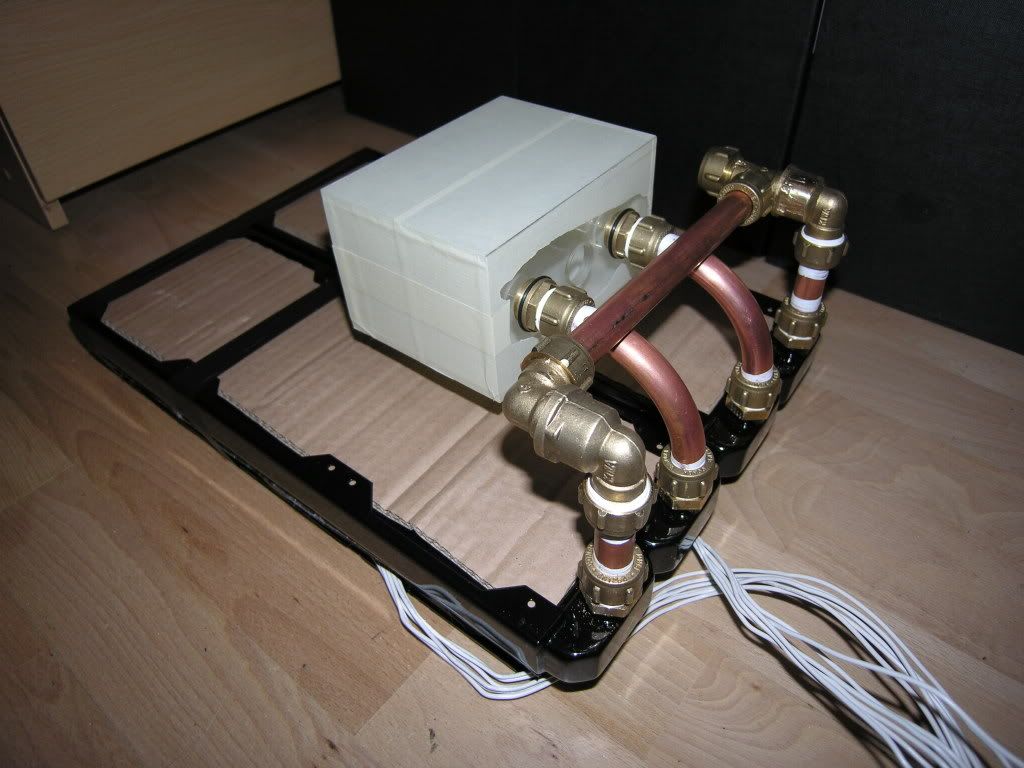
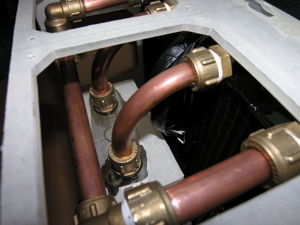
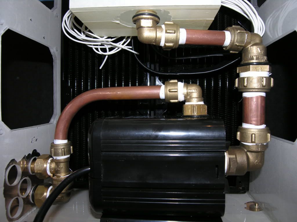
Plumbing in the res was definitely the trickiest bit so far. I quickly lost count of the amount of times that the rads were taken in & out of the plexi box for measurements & adjustments. The brass fittings were fitted on to the rads & res first. The 15mm pipe was then attached to the res & the other ends then attached to the rads. After a bit of tweaking & fine tuning it all lined up pretty good. The brown layer on the rads is just cardboard being used to protect the fragile fins.


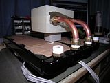
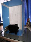
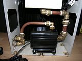
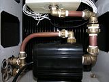
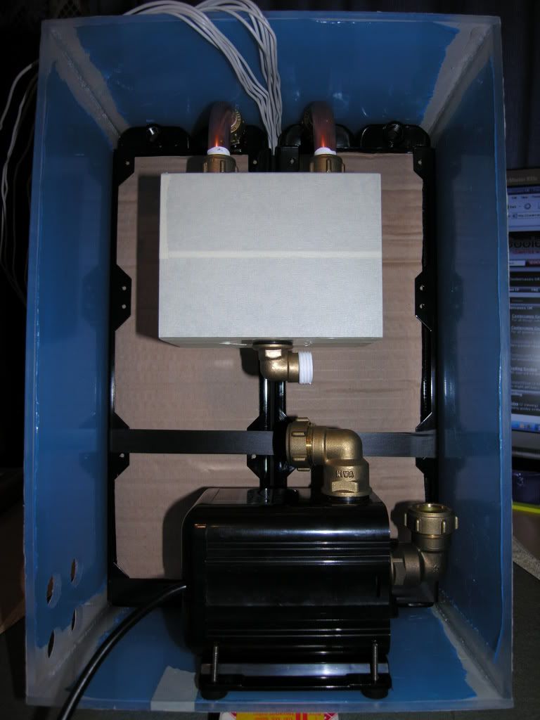
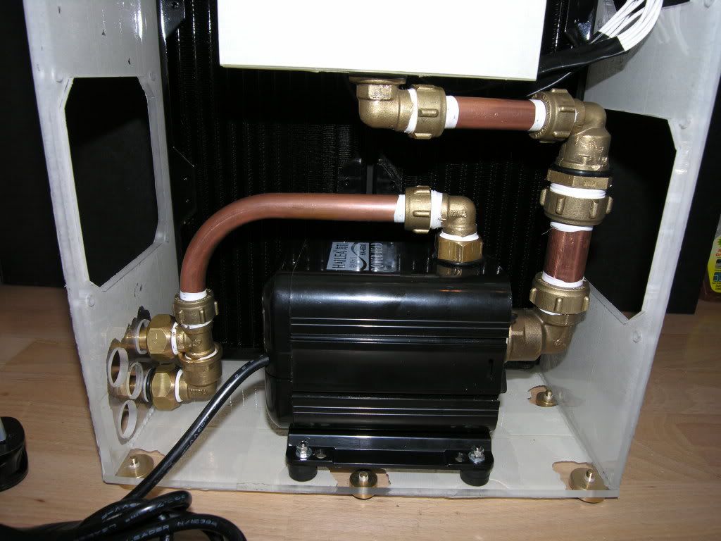
With the res in place the inlet pipes were then sized up & assembled. The pump was also put in place with rubber spacers as feet, to absorb vibration. Both connections to the pump were with 1" to 22mm brass compression fittings. They fit perfect onto the pump's own plastic threaded connections.


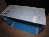
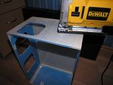
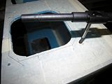
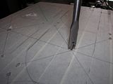
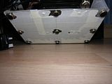
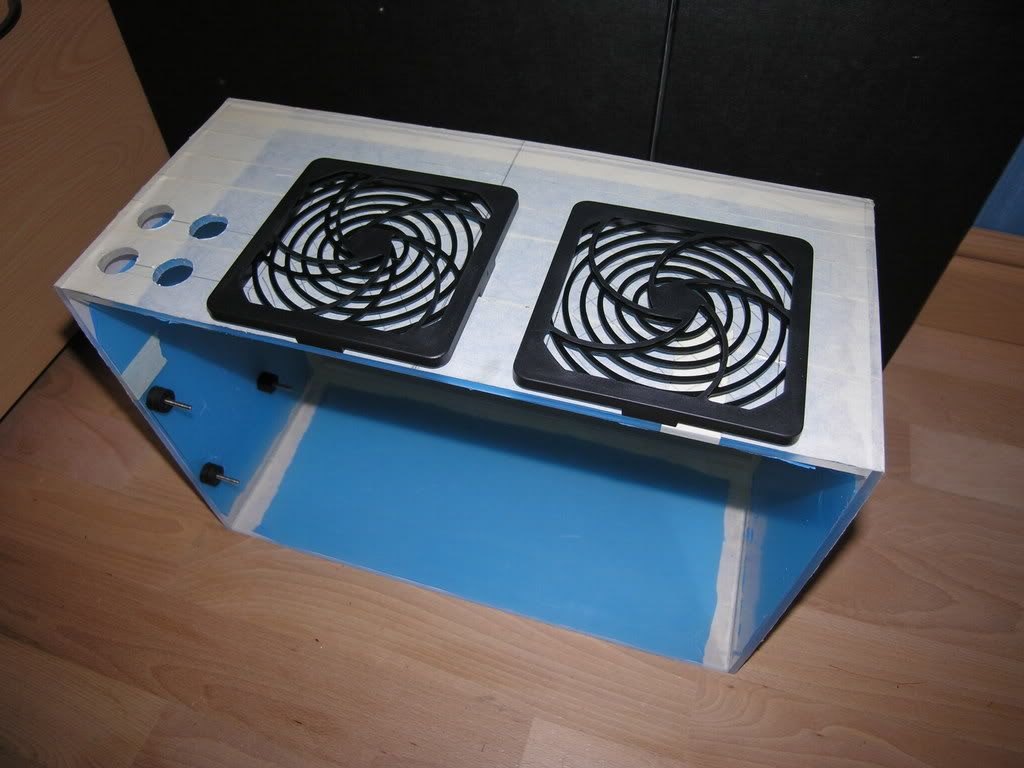
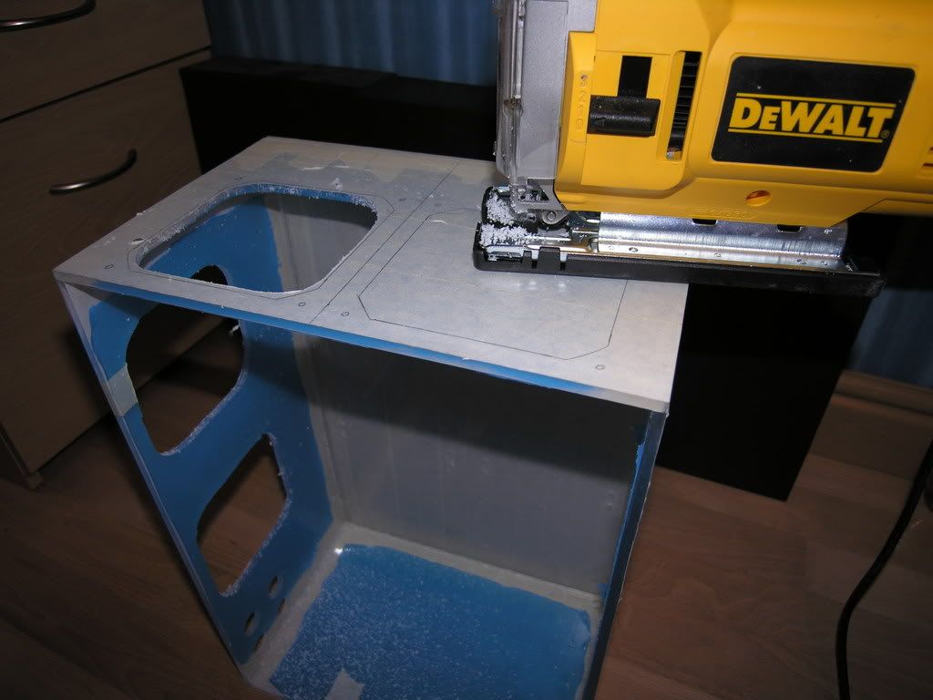
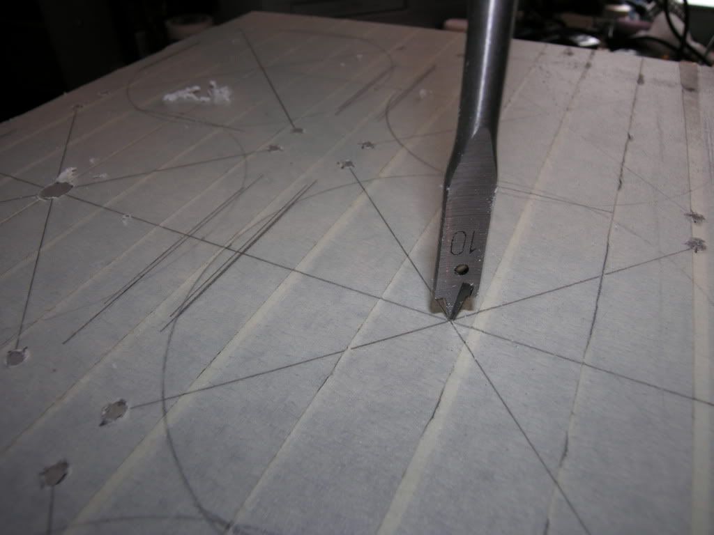
To get good airflow to the rads six vent holes were cut away from the sides & top of the case. The holes were drawn out to match the shape of some filtered fan covers that had been donated by a friend. A 10mm pilot hole was drilled into the centre of the area to be cut. Then using a Dewalt jigsaw & following the inside of the marked out line, the hole was easily cut away. To smooth the edges off, varying grades of hand file were used which took hours but was worth the effort.
The filtered fan covers are 2-parts, with the base being screwed to the case with M5x12 csk screws & the top part detachable with small clips for easy changing of the filter. I'll be giving these a spray when the case nears completion.

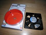
For the fan holes I had specifically bought a rather expensive hole cutter from B&Q. The closest size I could find was 127mm which I thought would be ok, as the diameter of the fan exhaust arc was 126mm. Obviously the holes would overlap the edges of the fans but they would still be mountable.
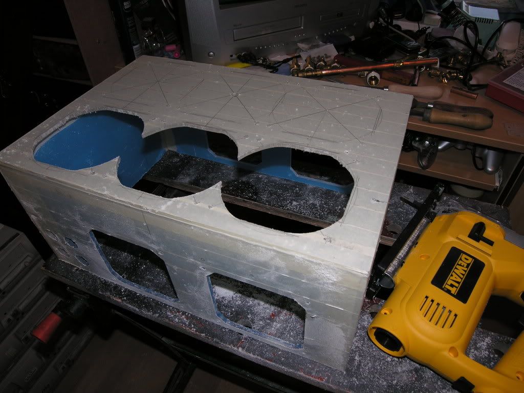
However, after getting some practice in previously with the Dewalt jigsaw (great tool!), I decided to cut the fan holes out with that instead. I'm glad I did as it was really easy & when cutting close to the line there was'nt much left to file away.

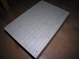
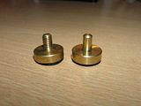
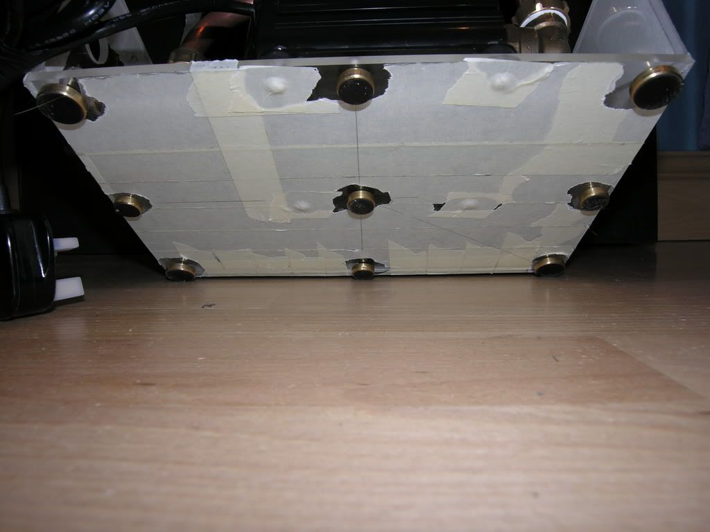
With all this added weight in the case it was becoming necessary to produce some sort of feet, to stop it sliding around on it's plastic base & to add stability.
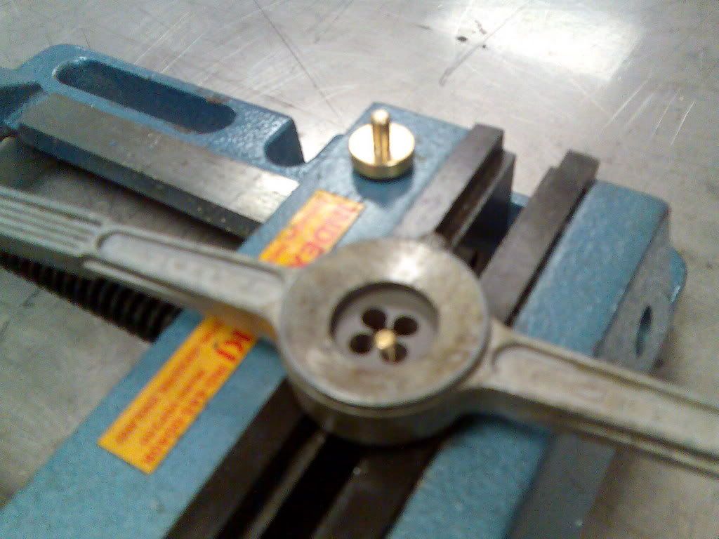
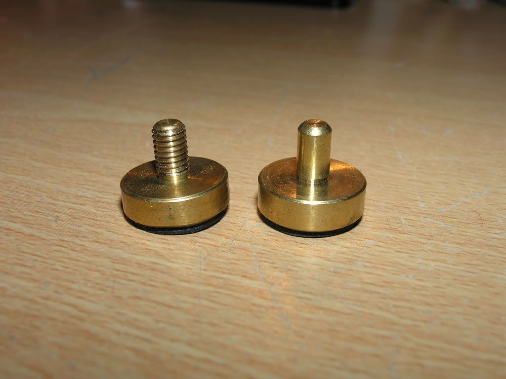
I had to salvage these prospective feet from about six plumbers' tap washer kits. They're turned brass tap plungers with a rubber base & they fit the bill perfectly. To secure them to the base the spindles were threaded to M5 with a stock & die, & respective holes drilled & tapped into the case's base.

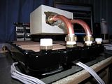
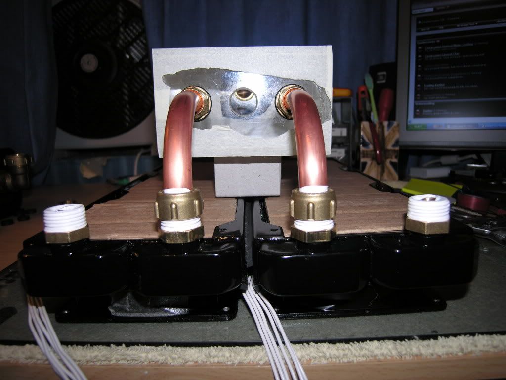
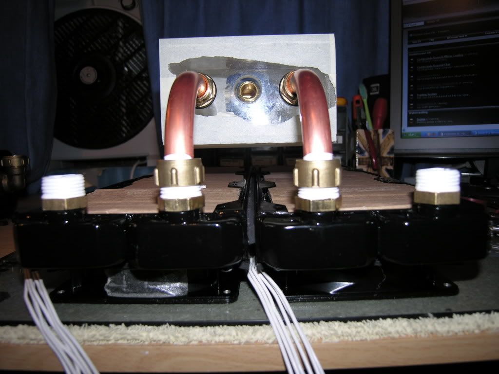
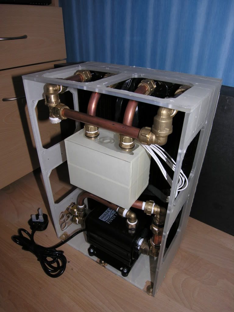
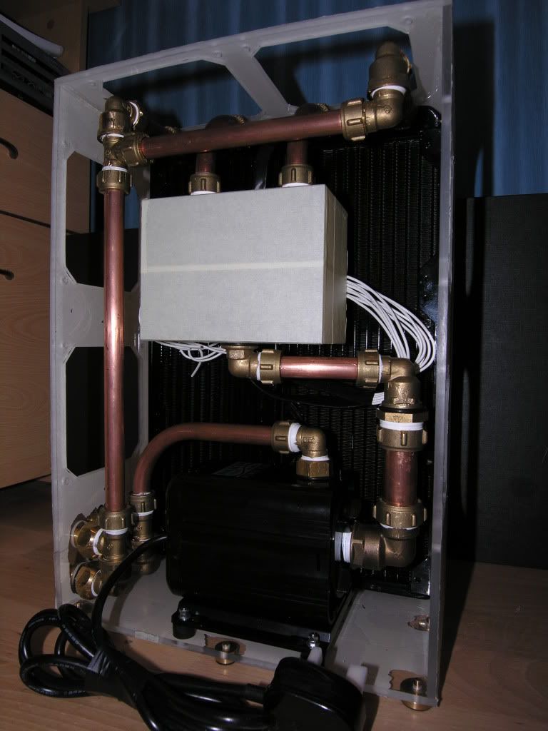
With all the basic plumbing parts prepared & in hand it was time to assemble this monster ready for leak testing. I felt like a contestant on the Krypton Factor getting all this stuff to fit together, the whole time silently praying for no leaks. I'll let the pics guide you through the assembly process.


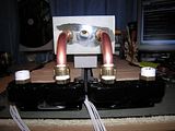
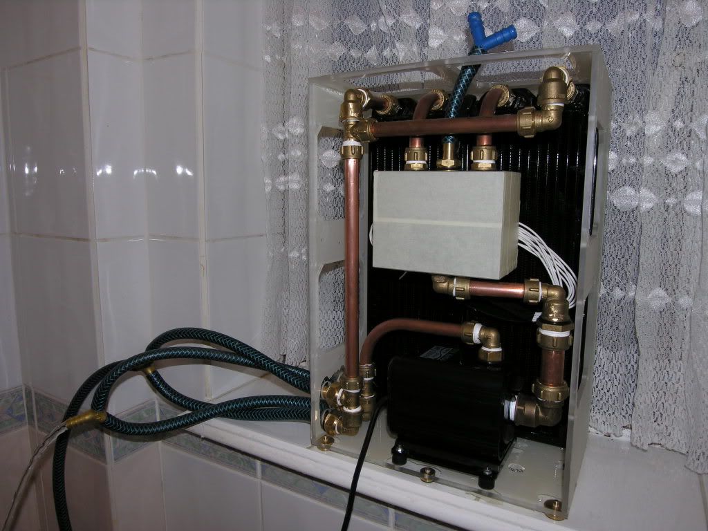
After a few assemblies & disassemblies it finally all fit good, so it was off to the bathroom to test it under tank pressure. I did'nt have any reinforced hose that would fit onto the 1/2" barbs, so I had to butcher a reel of garden hose which was the perfect type. I may even use it to eventually run the cold stuff to my PC's. Here's a pic taken last night, of the rig on my bathroom window sill connected to the tank fed water supply. If you look closely you should see water flowing from the outlet.
The tank fed test identified 2 minor leaks which were easily fixed with a tighten up & different sized O-ring.
When I get the chance I will connect it up to mains pressure, controlled of course! I'll keep you posted with progress as it is made.
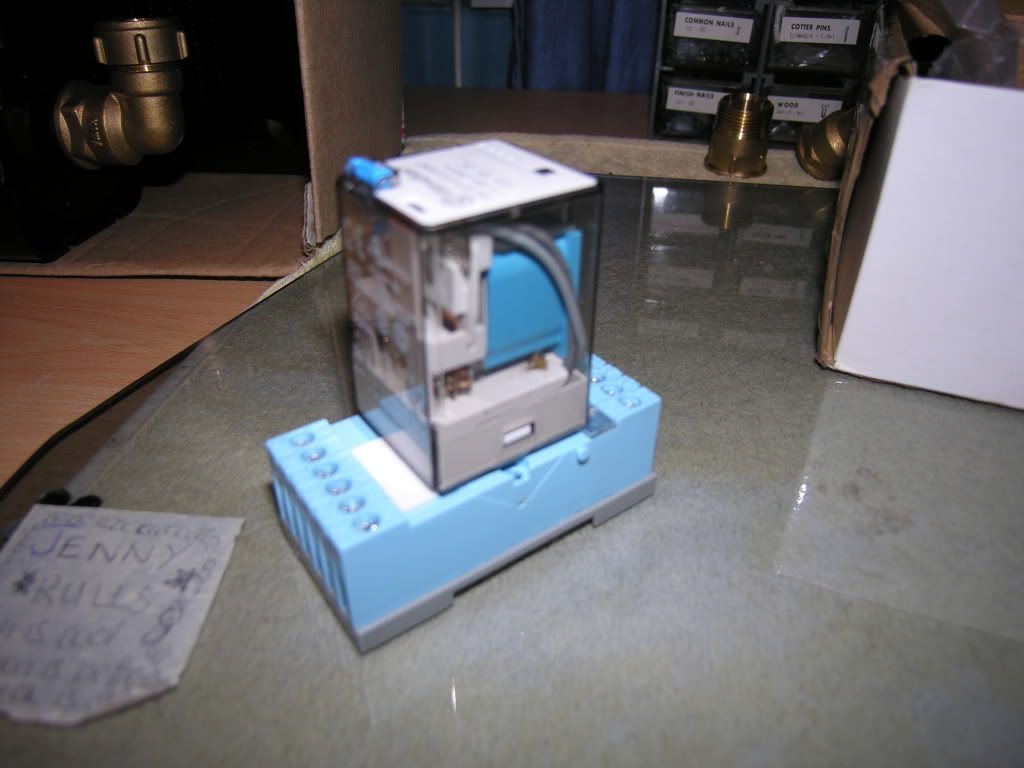
I still also need to wire in the electrical connections. I intend upon running a 12V line down to the box from my main PC to activate a relay upon bootup.

These connections will be terminated into DIN rail mounted connectors. The DIN rail will be positioned horizontally behind the res & suspended from the top of the case using two lengths of chromed 8mm pipe. I could'nt bear the idea of mutilating my beautiful res to support the DIN rail. I'll of course be incorporating a local switch for testing & local activation.
So what do you think? Any constructive comments would be gladly welcomed, especially on organising the log. :argue:
I actually started the build about a month ago & have tried my best to take pictures along the way. I reckon/hope i'm about 2 weeks away from completion.
Here is a sketch-up in MS Paint of the basic shape of things.
My motivation for building this is to be able to cool 2 PC's with one setup. I currently have a small form PC with no room to accomodate a rad, pump, etc & a tower system waiting to be put together. I love what other people here have done in utilising the space within their cases, so I may try an internal setup at a later stage.
I have built the box already using 5mm thick clear perspex. The front will be detachable, maybe held in place using small magnets for ease of entry. I saw this used on a case in another thread & thought it was a pretty sweet idea. Here's some pics of the starting stage. I used a cardboard box at first to give me a rough idea of dimensions & component placement. The sketch does'nt show it but there will be 2 inlets & 2 outlets, terminated using 1/2" barbs to connect the reinforced plastic tubing. (N.B. cat not included in final build!)


All of the pipe runs in this build will be with standard copper pipe. The connections to the Hailea HX-6530 pump will be with a female 22mm adapter. The rest of the runs will be in 15mm copper pipe. I'm using brass compression fittings to plumb the pipework in. I know I could have used solder fittings but I like the look of the compression fittings, gives it a gritty 'Kitsch' feel. It might also have something to do with having 2 large containers full of brass fittings getting in the way :crazy:


I've also completed the res too. I have made this from the 5mm perspex & it looks really nice. The 4 connections to it are made with 1/2" BSPP to 15mm fittings with O-rings to seal against leaks. The holes for the connections were drilled out to 19mm & tapped to 1/2" BSPP. I picked up a tap set off eBay for only £7.50. The drilling was really time consuming but I did'nt want to rush it & risk cracking the perspex. I started with a 4mm drill increasing the diameter 1mm each time. You should be able to see all the drill bits laid out in the end pic.


The connections to the res are made with 15mm compression fittings. All threads on the brass fittings are 1/2" BSPP. The holes in the res were drilled out to 19mm, which is the ideal tapping drill size for this thread. I could'nt get the 19mm drill to fit in the pedestal drill's chuck so I had to turn the shaft down to 13mm on the lathe.
To tap the 1/2" BSPP thread I picked up a great set of hand taps off eBay for £7.50. I could'nt find a tap wrench big enough for them, but found a pair of pliers to be adequate for the job.


Here's some pics of the tapped res without the masking tape. I got impatient & wanted to see how it looked :drool:

The next step was to mount the six EBM Papst 240v 119mm fans on the rads. I chose to opt for pulling air through mainly to have the fans at the rear. This was to stop them getting directly splashed by water during leak testing & refills. The fans are rated at 29.5dBA, pulling 84m³/h each through the rads. If they prove to be too noisy i'll think about incorporating a fan controller. To allow airflow into the case i'll be affixing six 120mm filtered grates to the sides & top.
Before mounting the fans on the rads, the rear facing mounting holes were tapped to M5 so that the fans could be secured to the perspex case.

I was fortunate to come across a reel of adhesive backed foam strip to use between the rad & fan edges. This should help prevent suction loss & maybe absorb some vibration.


I forgot to take pictures of the cabling & connections to the fans, sorry :nono: . I used 1.5mm single core cable soldered to the pins & shrouded to prevent direct contact. This was then run along the sides of the fans & held in place with clear cable ties.
The six fans were then secured in place with 4mm self-tappers on all four corners of each fan.
Whilst I was working on the rads it was a constant niggle that G1/4" was quite a pitiful size for the inlets/outlets. After thinking it through I had two real choices;
1. Tap out the existing threads to 3/8" (max. capable)
2. Use G1/4" fittings but ream them out by a few millimetres.
Looking at the G1/4" to 15mm fittings I had to hand, it was possible to open them up from 8mm ID to 10mm ID, so that's exactly what was done.

Plumbing in the res was definitely the trickiest bit so far. I quickly lost count of the amount of times that the rads were taken in & out of the plexi box for measurements & adjustments. The brass fittings were fitted on to the rads & res first. The 15mm pipe was then attached to the res & the other ends then attached to the rads. After a bit of tweaking & fine tuning it all lined up pretty good. The brown layer on the rads is just cardboard being used to protect the fragile fins.
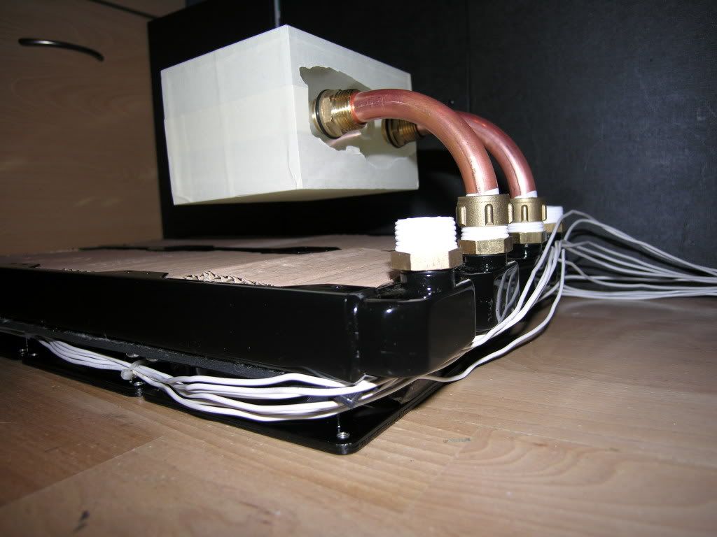
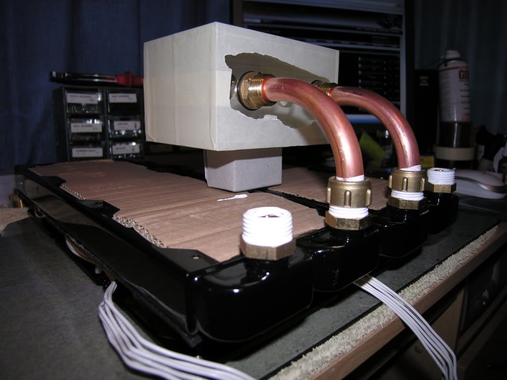

With the res in place the inlet pipes were then sized up & assembled. The pump was also put in place with rubber spacers as feet, to absorb vibration. Both connections to the pump were with 1" to 22mm brass compression fittings. They fit perfect onto the pump's own plastic threaded connections.
To get good airflow to the rads six vent holes were cut away from the sides & top of the case. The holes were drawn out to match the shape of some filtered fan covers that had been donated by a friend. A 10mm pilot hole was drilled into the centre of the area to be cut. Then using a Dewalt jigsaw & following the inside of the marked out line, the hole was easily cut away. To smooth the edges off, varying grades of hand file were used which took hours but was worth the effort.
The filtered fan covers are 2-parts, with the base being screwed to the case with M5x12 csk screws & the top part detachable with small clips for easy changing of the filter. I'll be giving these a spray when the case nears completion.


For the fan holes I had specifically bought a rather expensive hole cutter from B&Q. The closest size I could find was 127mm which I thought would be ok, as the diameter of the fan exhaust arc was 126mm. Obviously the holes would overlap the edges of the fans but they would still be mountable.

However, after getting some practice in previously with the Dewalt jigsaw (great tool!), I decided to cut the fan holes out with that instead. I'm glad I did as it was really easy & when cutting close to the line there was'nt much left to file away.
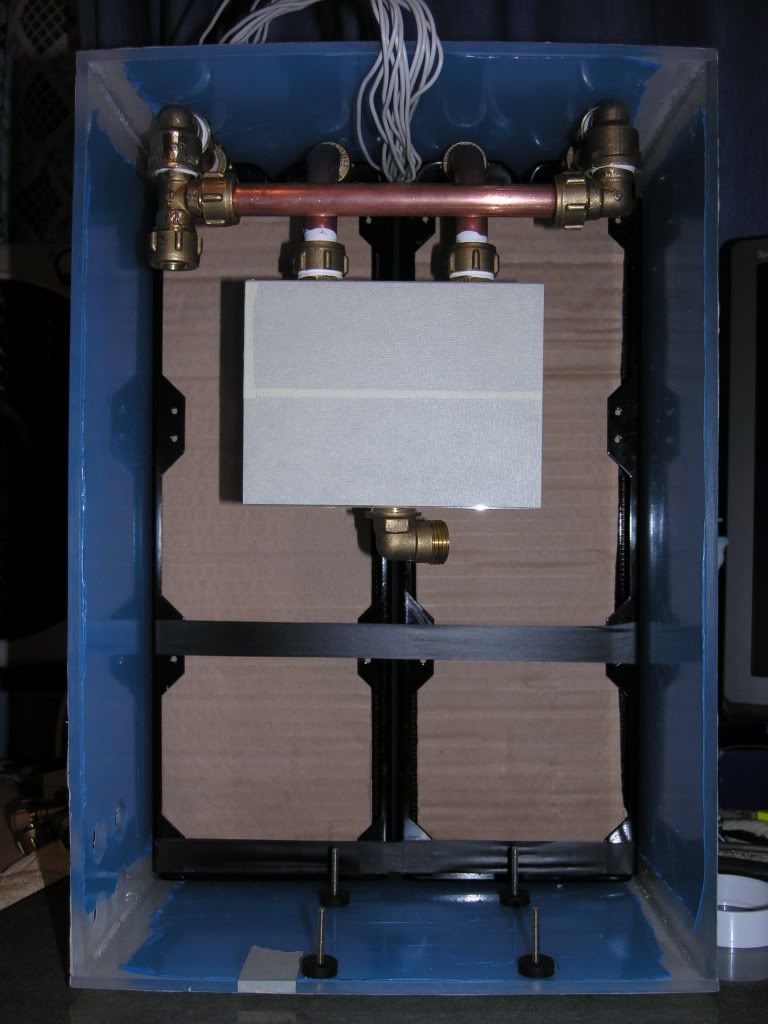
With all this added weight in the case it was becoming necessary to produce some sort of feet, to stop it sliding around on it's plastic base & to add stability.
I had to salvage these prospective feet from about six plumbers' tap washer kits. They're turned brass tap plungers with a rubber base & they fit the bill perfectly. To secure them to the base the spindles were threaded to M5 with a stock & die, & respective holes drilled & tapped into the case's base.
With all the basic plumbing parts prepared & in hand it was time to assemble this monster ready for leak testing. I felt like a contestant on the Krypton Factor getting all this stuff to fit together, the whole time silently praying for no leaks. I'll let the pics guide you through the assembly process.

After a few assemblies & disassemblies it finally all fit good, so it was off to the bathroom to test it under tank pressure. I did'nt have any reinforced hose that would fit onto the 1/2" barbs, so I had to butcher a reel of garden hose which was the perfect type. I may even use it to eventually run the cold stuff to my PC's. Here's a pic taken last night, of the rig on my bathroom window sill connected to the tank fed water supply. If you look closely you should see water flowing from the outlet.
The tank fed test identified 2 minor leaks which were easily fixed with a tighten up & different sized O-ring.
When I get the chance I will connect it up to mains pressure, controlled of course! I'll keep you posted with progress as it is made.
I still also need to wire in the electrical connections. I intend upon running a 12V line down to the box from my main PC to activate a relay upon bootup.
These connections will be terminated into DIN rail mounted connectors. The DIN rail will be positioned horizontally behind the res & suspended from the top of the case using two lengths of chromed 8mm pipe. I could'nt bear the idea of mutilating my beautiful res to support the DIN rail. I'll of course be incorporating a local switch for testing & local activation.
So what do you think? Any constructive comments would be gladly welcomed, especially on organising the log. :argue:

")