Project C-Macc's 2

mayhem

New member
Hi there to all.

I thought id join the forums and say hello to you all. I havent hit the requested ammount yet to be able to post liks or pics so ill just start off by telling you about a second Large mod im working on called C-Macc's 2 the revenge.

My first arcade system i built was featued in the UK mag custome PC a few moths back but after building it i found i grew to hate it as it was no built from the ground up in a style that i liked. So after a few weeks of hitting google sketch up i started to build my own from the ground up.

I Look forward to posting more details and a fuller work log as i build up my post count (might take a few days to do).

Take care for now

Mick
 
sponsored by Ultimarc at http://www.ultimarc.com you local source for High end arcade control's and the fantastic software front end Gameex at http://www.Gameex.net. All so im being sponsored as well By http://www.carcomputer.co.uk/. They supply a large range of Touch screens and small Screens that are excelent for modding. You may what to take a look they have some wondwerfull toys just waiting to be added to any good computer mod ...

logo_with_panel.jpg


logo.gif


mbt_shopping_header_05.jpg


A while back I took a jap candy cab and built myself a system that could play any game in the world. I re worked all the internals and upgraded all the hardware with in the cab so that it had the ability to play consoles to pc to old retro computing it was all covered. It has been and still is a big hit with everyone who gets to play her and always draws a whoo “How many games” …. And all ways the question “does it have so and so game?” which has always followed with a few clicks of the buttons to reveal it hidden surprises to its amazement of the guests. Followed by many hours of finger bashing pleasure that any arcade owner would be proud off.

Now as per the norm some people like the system and some who well they don’t but they are normally people who have never seen the system in the flesh and only seem to criticize for no good reason. There however was a few question’s that made me think and a few real “What ifs ?” that made me wonder.

Pics of the Past C-Macc’s below


But and this is the big but I was never realy happy. I hadn’t made the casing myself and all I had really done was introduced a way that all the systems could work together in harmony and beefed up the electronic components inside I needed more (I called it my ½ Mod). I decided to redesign a new model arcade system which I first called I-Macc’s but after finishing off the frame work and taking my time to view it in all its glory I decided it was not what I was after. It just didn’t jump out and kick you in the teeth. I was not happy.

Here are a few Pictures of I-macc’s from Concept to frame work before I took a saw and sent it back to the depths of depravity.

I-Macc's


I started up Google sketch up and after a few hours of learning how to use the program I went under my merry way of a complete redesign of the sub frame and control panel system. Now this took a few weeks of pulling the design apart and re configuring everything and well as you may or may not know just hammering away till it looked right and was feasible. I then started to build the 2nd frame but after the frame was built I came to release that I had missed one vital error and that was the width of the screen was to big to be seated on the frame work correctly and there was no way to fix this problem .. so I had started again but this time taking into account the Screen sizes.

Below are some Pics of the concept views of C-Macc’s 2 and a YouTube Video that I put up.

C-Macc's 2 The Revenge


and this is the Youtube Video i put up a while back


Link in case it doesn't work properly - http://uk.youtube.com/watch?v=L6-9kRb7JEU

So with a few ups and downs and with the recession seemingly hitting every one very hard I proceeded with my plans and started work on the sub frame of C-Macc’s 2.

Now to point some thing out before others do this frame work was basically designed around the looks of a Sega Naomi arcade cab but with some major design differences. You'll see them as the build carries on.

Sega Naomi Cab


Its taken quite a good few weeks to get this far due to the above problems but things are starting to look up. The frame work is built using Hollow steal 2 x 1” and this is what it looks like so far without the TV bracket mounting. Im stood next to it to give you a good idea of the size of the frame work.

Now some Pics of some of the work so far ...

This is the basic frame work complete with out the TV mounting fitted.


Now that will do for now ill post up more as the project progresses. Hope you enjoy the work so far. Im open to comments or suggestion of my project.
 
Time fly’s when you having fun. Here is a 32″ Samsung LCD Fitted. Ive taken photos at different angles on the frame. It will house up to a 50″ Screen which might be just a little to big for most but when i get the chance ill show it with a larger screen later on. Time to crack on learning wood work now lol. if next time i come on and i cannot type its because ive never in my life used a new tool called a Circular saw that ive just bought hahaha … finger liking good stuff …..


Some more shots of the Cp Being made . As you can see its changed lol ...

DSCF346.jpg


DSCF3461.jpg


DSCF3462.jpg


DSCF3465.jpg


Well a massive fu?? Up on my part. while fitting the CP back and forth working on dimensions i caught the spintrak wire and basically ripped it out. The damage is in the pic below.

DSCF3470.jpg


----------

i didnt know the wire lay out so i took a multi meter and figured it all out.

from left to right ..

Left =5v

next = x1

next = Ground

last = x2

so then i basically i ground down the broken trace then used window quick silver which is the same stuff used for trace repair. left it 5 min then soldered new wires. Tested and working fine .. thank god ...

happy as larry.

DSCF3473.jpg


this was a big mistake that could have cost me £60 luckily im used to trace repairing on xboxs and all so graphic cards and lucky enough i had the tools at hand to do the repair.

If you ever going to do a trace repair dont ever have a soldering iron hotter than 15 watts else you going to Burn off more trace. I personally have a adjustable soldering iron than can do from .2 watt to 500 watt witch all so has a Blow torch fitted for lifting things such as GPU's (yes i have replaced a GPU at one time when i chipped it when placing a DD WC block on it lol).

a few more pics. Still working on the CP just added the base (not permanently though) Did some more work sanding down as you can see from the wood work my skills are real poor but at least im giving it ago. I still need to some how tail the back end off as i relay am not happy at the way it looks at the back end when fitted.

I wont be able to have the draw for the Joy pads but thats fine as i can add one in the main body. Still loads of work to do but pics below any way for you all to lol at my bad wood working stills but good wood filling skills .... lol

Last pic you can see i played with my new router hehehe .. i love its lol .. ill be routing every thing round the home now.

Need to go tidy the kitchen before the lass gets home else shell kill me ...

DSCF3476.jpg


DSCF3477.jpg


DSCF3478.jpg


DSCF3481.jpg


Routed

DSCF3487.jpg
 
Been working a little more.

The CP has been Shrunk by 2.5" and the Frame arms have been cut by 2".

The Back peace has now got a False wall of 1.5" to allows cables to be hidden behind it. 1 Shelf inside has been added will do the second and third Hidden shelf for the electrics another time and loads of wood filler has been used again lol ...

Still loads of work to do but shes starting to take shape now.

DSCF3490.jpg


False wall

DSCF3492.jpg


Single shelf

DSCF3493.jpg


A bit more work done. The keyboard tray has been made and installed. Cannot fit a side draw for the console pas as there is just not enough room which is just a shame. Started to smooth off the wood for the CP and spray painted the cp with a under count just to protect it for now. Pics below of the work on the cp so far.

DSCF3496.jpg


DSCF3495.jpg


DSCF3494.jpg


Still more work to do but until I get the rest of the parts I need for the CP this is the limit of work I can do for now….. Its now all down to when others can either deliver my parts or finish off the work that ive requested to be done ….

DSCF3506-1.jpg


DSCF3505.jpg


DSCF3504.jpg


Time for a small Update.

Well i have put in the shelfs and allso been working on the Doors for the front.

Here you can see the work done on the front.

DSCF3507.jpg


DSCF3508.jpg


DSCF3509.jpg


I then did the door with White plastic Spay can undercoat as per OMDs build logs and then the surrounding frame with black plastic under coat. Once that had dried i used Grit 2000 wet and dry and sanded down . I then did a fine mist of white on the black and black on the white and again rubbed it down with 2000 Grit wet and dry. This revealed a fair few dimples and large deep air lines marks on the wood so i filled them and sanded it down again. I then re undercoated it all.

Iafter 24 hours in the airing cupboard and a pre warning to every one in the house to stay out i then pulled them out to find a grate big dent across one of the door (was i annoyed i think so) My kids had thrown in some plastic toys and damaged them ...

So again after filling and redoing the under coat and another 24 hours i then used Gloss white car spay paint on the doors and Matt black on the frame work. And again after sanding down with 2000 Grit wet and dry and re doing it all again a few times i then left them 24 hours to harden ad dry but this time i fitted a lock on the airing cupboard to stop any mishaps lol ....

#

Once the 24 hours was up i then re sanded them down with 2000 grit wet and dry and applied several coats of clear Lacquer and left them for 8 hours and then wet and dried and re lacquered them. Once that was done and dryed after 24 hours i then fitted the locks.

I still need to polish them but ill do that laster on. Pics below ...

DSCF3514.jpg


DSCF3517.jpg


DSCF3521-1.jpg
 
I had to change the moniter to a VGA connection version.

So i have orderd this from http://www.carcomputer.co.uk/

Lilliput EBY701-NP/C/T

7a0ddbb60f4981e9d56b80af5f621d0e.jpg


Now for the specs

Specifications:

MODEL:EBY701-NP/C/T

COLOR SYSTEM:PAL-4.43 / NTSC-3.58

DISPLAY SCREEN: Diagonal 7 inches/ 178mm (15:9)

DOTS PIXELS:1152000 pixels(800*480)

AUDIO OUTPUT: ≥100mW

CONTRAST RATIO:200:1

BRIGHTNESS: 400cd/m2

VIEWING ANGLE: 45/60(U/D),65/65(L/R)

INPUT VOLTAGE: DC 11-13V

POWER CONSUMPATION: ≤10W

DIMENSION (mm): 192×115×30

Now after much research i found that the 800*480 is just the moniters Res. Ill be running it at 800*600 giving me full scope to run it with GameEX.

Ill post more info and pics of this excelent peace of eqipment once it arrives.

Working on another panel, this time its the base panel.

Again we start buy getting a send belt sander and then using 100 Git run it over the whole board. This rips up the rubbish revealing all the pits and tears and holes. Then using filler i fill what i can see and trust me what i can see is only half of what is there.

Pic's of the wood before i start -

001.jpg


003.jpg


004.jpg


First set of filler layerd down

005.jpg


006.jpg


007.jpg


010.jpg


Then i sand it down with set and dry 180 Grit and then take another look. Again there is still loads of pits and holes so off i go again filling and sanding. I had to do this 5 times and it took about 3 hours to do.

1st coat of filler / primer and again more filler.

013.jpg


014.jpg


015.jpg


3rd primer filler and sanding.

021.jpg


Once i was fairly happy i then used Prim filler and undercoat from a spay can and then give it a good spay over. I do this 4 times at 15 min intervals. Once its dried i look again and fill all the holes and pits with filler and then again sand down with 180 grit wet and dry. Once the ready i then layer over 3 more coats of filler / primer. This takes about 40 min to do. And again I look for more pits and holes and marks and again i do the same as before. All in all its takes about 12 hours to do to get its close as possible to what i would call near flat.

5th sander filler and priming....

022.jpg


023.jpg


On the 5th time ive moved to 400 grit wet and dry sand paper.

Getting there ....

Added 1 coat of plastic primer after sanding down with 1200 Grit wet and dry.

026.jpg


027.jpg


then a second coat again sanded with wet and dry 1200 grit after 1/2 hour

028.jpg


029.jpg


030.jpg


and then stuck in the airing cubord for 24 hours .....

Thats the base done for now it will be painted later on. ill be working on the tray now for the PC to fit on., Im using Floating brackets that will move the whole PC out of the cab. so you have full access to the PC and will not have to jump in undernith to get access.

And last but not least im being sponsored as well By http://www.carcomputer.co.uk/. They supply a large range of Touch screens and small Screens that are excelent for modding. You may what to take a look they have some wonderfull toys just waiting to be added to any good computer mod ...

mbt_shopping_header_05.jpg
 
Lilliput EBY701-NP/C/T

Well My little Lilliput arrived from http://www.carcomputer.co.uk/ today. I must admit I'm very happy with it. there are a couple of niggles but these can easily be overcome. Any way on with a small review of the item in question the Lilliput EBY701-NP/C/T.

Delviery.


The screen came well packed in a over sized box. First it had Bubble warp around it then polasyrene Peanuts. This was excellent and only took 2 days to arrive. Thank you to http://www.carcomputer.co.uk/ , some places like to make you wait so that a big plus point.

The Box on the outside doesn't really contain that much info and is a pretty normal boxed LCD. There is a Photo on the front that has a picture but this is not of the actual tft screen its of another screen the HR 701-NP which got me a little confused at first as i did not order that version. Photos below of the box.

003.jpg


004.jpg


005.jpg


Whats inside the box


on opening the box you get a small flap with "Car Entertainment world" Written across it. On opening this flap you get to see it all neatly in place and well sealed up and a nice piece of paper warning you to check everything before you remove the seals. If you remove the seals and something is missing you will get a restock Charge of 25% which would equate to Approx a £40 charge this is quite a stark realty check. It all so Warns that if the seal is broken then the screen the warranty is Void (Consider it Void before i even opened the box) .... Taking note of these pre warnings i then put it to the side.

Below you can see a nice selection of cables and the wrapped TFT Touch screen.

• VGA extension lead with USB adapter

• AVI / Sound / VGA Brake out lead

• Docking station for the screen with a Sticker on it for mounting on dashboards if you so require.

• Small remote control

• UK power adapter rated at 12V * 200 Milliamps

• A cigarette Lighter Power Supply with Suppressor (nice to see)

• Black and white Manuel

• Driver CD for touch screen interface.

006.jpg


020.jpg


021.jpg


023.jpg


033.jpg


Once all the packing was removed and checked for damaged i took a look at the screen it self. Now the screen feels quite heavy which is a good sign and feels quite robust. The buttons have a nice solid click to them when depressed and are raised about 1 mm from the surface. You can see the IR receiver is Just above the buttons on the right which doesn't look out of place and is in a good position. I hate receivers at the bottom of the screen as sometimes you have to lower the remote for it to work correctly. One thing i was suppressed not to find was a protective plastic layer over the screen itself.

008.jpg


010.jpg


019.jpg


028.jpg


On the back side there isn't that much to see. You get the Sticker with the model no but there is no serial number which was different. On the left hand side you can see the Brake out cable input as well as the power supply plug point. You can all so see the speaker holes to the left on the back plate. and the mounting point for the dash board mount. One thing i noticed straight away was there are plenty of air vents dotted around the back and again this is good to see. All so there is a Styles' holder on the back left with a styles inside.

011.jpg


013.jpg


015.jpg


017.jpg


Yes.

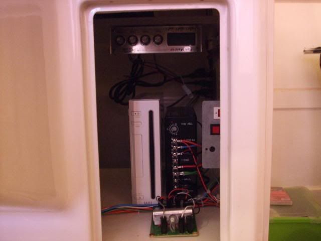
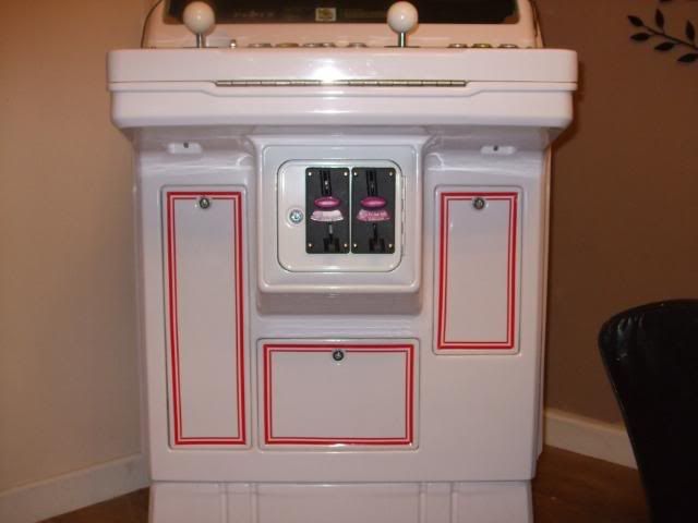
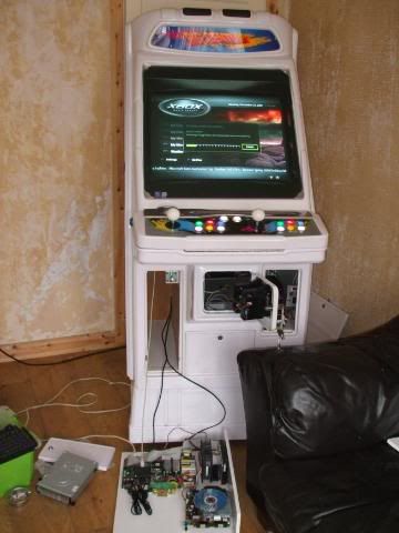
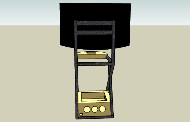
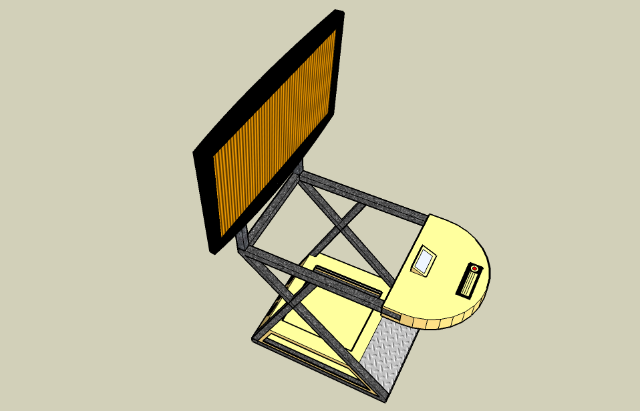
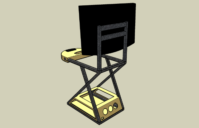
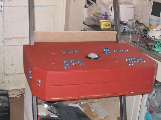
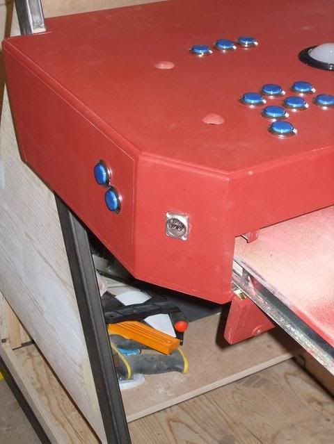
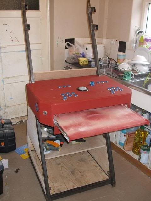
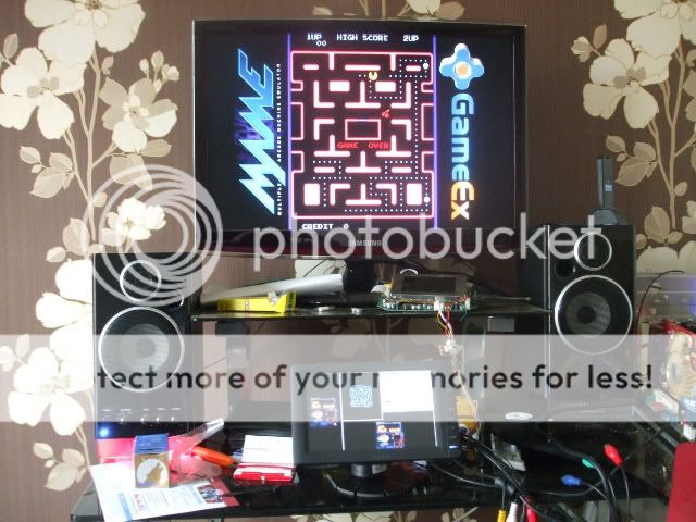
The LCd is going to be incorprated into the CP. The LCd will Give info such as Time played, CPu info, memory Info, Game, Marque, box info, controller options and more. Allso allow for Juke box mode ...

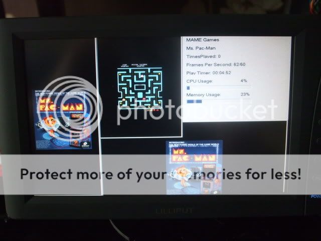
Here is a quick pic of it woking but this software is still being tested.

048.jpg


047.jpg


With its touch screen youll be able to do other things as well. This is taking the expreance just that little bit further .......

Allso hepfully if tempest can get it to work it will do previews of the games as well

{click on pic for a preview}


Oky more info on the Lilliput EBY701-NP/C/T from http://www.carcomputer.co.uk/.

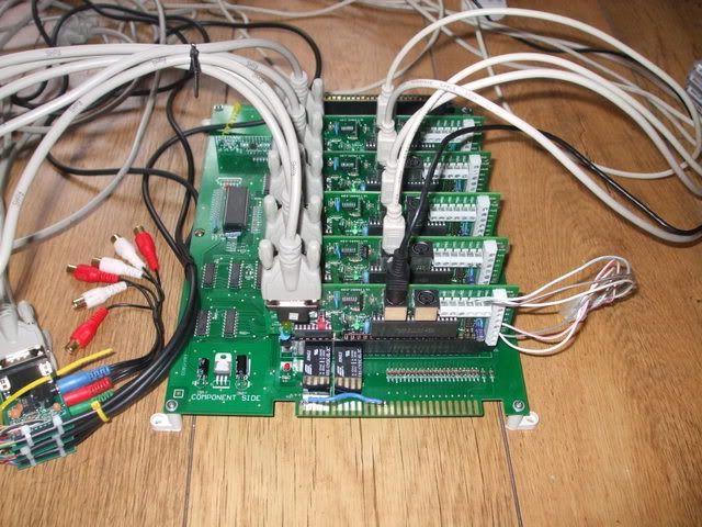
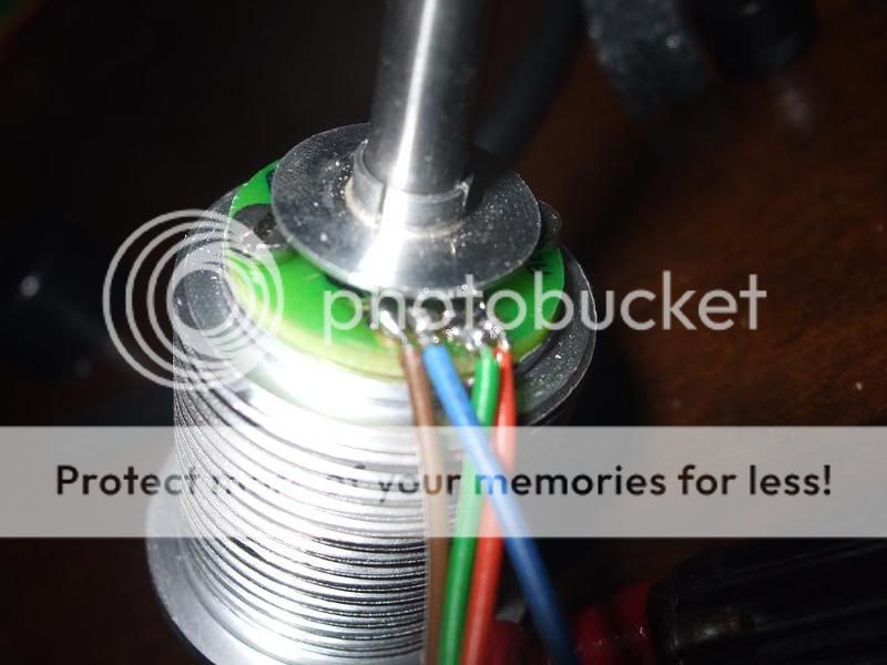
The brake out cable for the touch screen is very well made it has 2 Wings that you depress to fit the lead to the monitor. It is very good as once it is fitted it is going no ware fast. The powe cable is standard and has none of these features.

Photo of the lead.....

The pen

Once thing im not to impressed with is the Pen that comes with the system. after a little play i found the pen feels like it is scratching the surface of the screen and feels real cheap in dead. After 2 times of pulling it out of it recess of the back of the screen it then became lose. The pen now doesn't seem to hold its place very well. So my advice would be to go out and buy some nice pens for the Nintendo ds instead as these feel much smoother but will not fit in the back which is a shame.

The remote control.

To my surprise it also came with a remote which i didn't see till it fell out of the box from its hidden recess. Now the remove is a very cheaply made remote. It can turn off and on the monitor and flick between the av / Tv settings quite easily. At distance its to say the least a bit dodgy mind you saying that its not a bad thing as these were made for a car not a living room so its not a big problem. One thing ill say which may sound a little wired is that it did not change over my 42" Samsung TV in my living Room. Why did i say that .... well its because i have several MP3 player's that have these cheap controls and when playing with them in the past they have turned over East Enders (which does not impress my lass) this one didn't do that thank god ...

Pictures of the remote... (ill take some after as ive just found it lol)

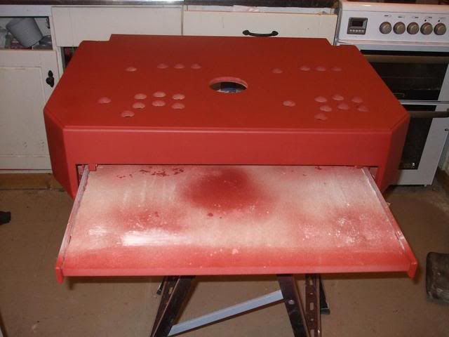
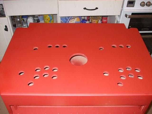
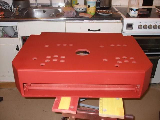
Installation of the Lilliput EBY701-NP/C/T.

One thing that was missing from the box is the fact it doesn't come with a DVI to VGA converter but to be honest at the price its cost it is defiantly not a deal breaker. You can get you off line for as little as £1.50 if you look round or by asking at your local computer supplier. Now the Brake out cable comes in two sections. There is a din style plug on the end that connects the VGA brake out section. All you do is screw this together. Again nice idea as this stops it from being pulled apart. The total length of the cable is approx 4 foot which is a good length. This can be extended with a monitor extension cable. There is also Audio in built into the cable(mono only) but these are only a few cm long so you'll need to get a extension cable for them if you like to use the sound on the screen. I won't be testing the sound as i have no need to use it. There is all so 2 yes 2 RCA jacks for video. I presume these are for extra systems on a car for the likes of reversing and the like. But that is handy to know for maybe a hidden 3rd screen for system setting and such things ;) ...

021.jpg


022.jpg


029.jpg


030.jpg


USB - 4 wire retentive Touch screen system and software.

On the brake out able there is a USB 2 cable that attaches to the PC for the Touch screen system. Do not install this until you have used the driver cd and installed your drivers . Now for a list of supported systems that the software supports ...

• Windows 98 SE, ME, NT, 2000, Xp , Xp 64, Vista 32, Vista 64, Dos (in fact all MS OS's)

• Linux

• Mac

• Windows CE

• Embedded XP

• HP Digitizer 32 and 64

• QNX Neutrino RTOS v6.3

(now come on this is excellent i think some Hardware makers need to take note of this company)

The CD also contains OLD drivers and PD Documents for the system and even teaches you how to build your own modules for Linux (My lass had to revive me after i saw that).....

Now the software is created by eGalax - http://210.64.17.162/web20/eg/drivers.htm (Driver there) Just in case you need them. Latest Version is 5.0.1.5310.

Ill not go into the software to much but it contains every you need to get the system up and running and works well. I have tested on Xp , Xp 64, Vista and Vista 64 without any problems what so ever.
 
On with some painting .

The base bord was then smoothed down with wet and dry 1200 grit and then painted with Black spray paint.

after 4 coats of black paint and then sanded down with 2000 grit wet and dry.

Then i layerd 6 coats of Varnish on the wood and wet and dryed each coat with 2000 Grit wet and dry and then once it all had dryed after 24 hours added the rails.

(ive del some pics by accedent)

001-1.jpg


002-1.jpg


As you can see the rails extend right out and this is how the pc will be fully accessable from the front of the cab. To add to that the Rail allso unclip off allowing the Pc tray to be un hooked and worked on with out the need to be near the cab :) ...

Bad wood working skills test fiiting the TS to a CP. Its a little tight but it goes lol ..

Had to lose the warrenty though :) .... Speaker has been remove and the back pannel has gone to boot as well. Ive sticky taped the back PCB to the back of the screen to hold it into place. that babys is going no ware fast i can tell you.

This is not the final (could be though) but more over giveing me idears how to fit it.

HPNX0025.jpg


HPNX0026.jpg


HPNX0028.jpg


HPNX0029.jpg


HPNX0033.jpg


Well a few more updates.

I've been working in the crazy British weather. One min it dry and lovely next is ****ing down with rain and boy does that annoy some one whose just spent a few hours spay painting. Any way on with the show as such ...

To start off with I Painted the top Sliding draw for the PC to fit on and then after a few days of it hardening in the airing cupboard i proceed to use T-Cut and polish on the wood to get a smooth deep shine.

HPNX0034.jpg


HPNX0035.jpg


HPNX0036.jpg


HPNX0037.jpg


After a few about 20 min of letting the polish filtrate i then give it a good rub down with a cloth.

HPNX0051.jpg


HPNX0053.jpg


HPNX0054.jpg


As you would expect it has a nice deep fish to it.

Next I proceed with the Touch screen Cp and sanded it down and then undercoated it a few times. Pics of it in different stages below.

HPNX0038.jpg


HPNX0039.jpg


HPNX0041.jpg


HPNX0042.jpg


HPNX0043.jpg


HPNX0044.jpg


HPNX0045.jpg


HPNX0046.jpg


HPNX0047.jpg


The low and behold it started to rain ... arrrrrr...

HPNX0048.jpg


HPNX0049.jpg


After drying it down and waiting for the rain to stop i then did a quick sand down with 1200 grit wet and dry and then spayed plastic coating over the top.

HPNX0050.jpg


The once that is dry you supposed to wait 24 hours lol ... did i hell. I then started to paint it.

This is the vairous stages of layering paint on the lcd CP ...

HPNX0056.jpg


HPNX0057.jpg


HPNX0058.jpg


HPNX0059.jpg


HPNX0060.jpg


HPNX0061.jpg


HPNX0062.jpg


HPNX0063.jpg


HPNX0064.jpg


Then off to dry in the airing cupboard

The boy 4rm oz thank you ...

Another load of build pics for you to looks at. First we have the LCD mock up set up and then its been layered with varnish. There is how ever still some damage to the system due to the lovely British weather but that's just life. im sure once my kids get their hands on it it would be worse ...

HPNX0067.jpg


HPNX0069.jpg


HPNX0070.jpg


HPNX0071.jpg


HPNX0072.jpg


HPNX0073.jpg


HPNX0075.jpg
 
Then i fixed the LCD section to the base CP and then re sprayed it a few more times ..

HPNX0077.jpg


HPNX0083.jpg


HPNX0084.jpg


Once that was all dry i then polished it down. you'll notice some damaged due to the weather but that is just life and since there i need to put a graphics and also a plastic over the top its not to much of a problem.

HPNX0085.jpg


HPNX0086.jpg


HPNX0088.jpg


HPNX0089.jpg


HPNX0090.jpg


HPNX0091.jpg


and to complete this round. here are some photos of hopefully what its starting to look like....

HPNX0093.jpg


HPNX0094.jpg


HPNX0095.jpg


HPNX0096.jpg


IMG
 
name='daniSAUR' said:
This looks tastey! How long's it taken you to get this far?

Its taken about 4 months i think from start to to were i am now. there have been alot of changes to the project as ive moved along and a couple of frame redesigns ...

Sorry about such a large start off post but im about 1/2 the way through the build and would you believe it i missed off a hole heap lol ...

If there any questions at all ill be pleased to answer them, If there any tips ill be pleased to hear them. I normal find no one says any thing on the other forums :( ....

Im not currently sponsored on any hardware for the pc parts as of yet because each time i try i get wired messages back from company's which is not surprising but when i first did c-macc's 1 i got over 1 million hit and ended up on many sites such as en gadget and more. im hoping this one will have the same effect. The only big problem with that many hits was it was hosted on a small forum and it caused it's collapse at one stage.

I all so had some friction with a couple of mods on there and eventually they just ripped down all my work logs and became complete dings over it. But hay that's life and you learn from your mistakes.
 
thank you

I missed off some Vids of the system of me working on certain parts and figuring out lighting ect ect ->

videos of the idea behind c-macc's 2 and demos ect ect

http://www.youtube.com/watch?v=L6-9kRb7JEU

First we have light to sound on the track ball

http://www.youtube.com/watch?v=ks1rLDR8gy4

Then we have Lighting for the the buttons on a temp CP ->

http://www.youtube.com/watch?v=7urMokvJOZU

demo shots of me working on the software for the touch screen. It in a more advance stage now but at least it will give you an idea of the goals of the system and why im putting in a touch screen ..

http://www.youtube.com/watch?v=61QsSA5t7D8

last but not least C-Macc's 1 build demo vid . loads of photos of the first one ..

http://www.youtube.com/watch?v=bZ2JDDglNus
 
Just got my 1/2 bugged camera back so here some photos of the cp so far. Hopefully there a little better.

If fitted some more stuff but there is still a lot more work to do.

085.jpg


086.jpg


088.jpg


091.jpg
 
name='DeMoB' said:
Nice looking controller :D

(Must show up fingerprints like crazy :p)

Dan

Not realy its car paint and when you touch a car it doesn't show unless you've been eating some greasy food lol .....

name='Ya Mother' said:
Thats a lot of graft you have put in there.

Erm you could say that and its still got a long way to go lol ...
 
Back
Top