How the heck did I miss a thread like this??!?!?! A thread full of stuff I'm VERY interested in from a quality modder! Subbed! Better late than never!
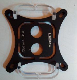
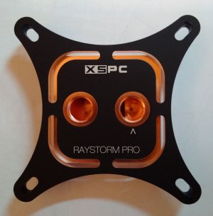
Great work as usual Blade Runner! I've been dying to RGB my original Raystorm, but 3mm RGB LEDs don't seem to exist, and I don't think the block is big enough to bore out the holes to 5mm.
Cheers Bartacus, better late than never

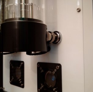
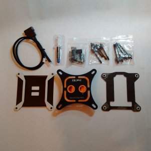
I did an RGB mod on an original Raystorm CPU block on the other build I did, "Dave" I have finished that build but not posted the completed pictures yet.
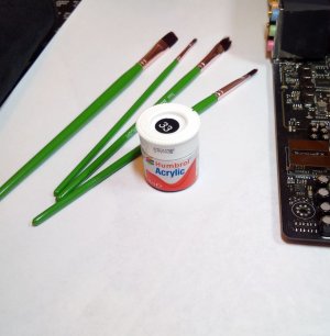
I didn't drill out the 3mm holes, that always ends in splintered acrylic I have learnt to my cost

, I drilled 2 new ones at 2 O'clock and 4 O'clock.
The acrylic is not solid on the Raystorm, those 2 positions was where there was the most acrylic to drill into. Even so I still got splintering but thankfully on the inside where it is not seen. Before you do this mod you have to be prepared that it may well go wrong and you wreck the piece.
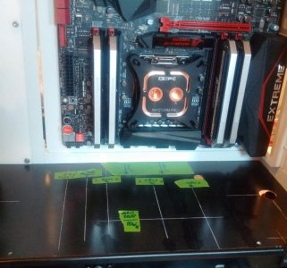
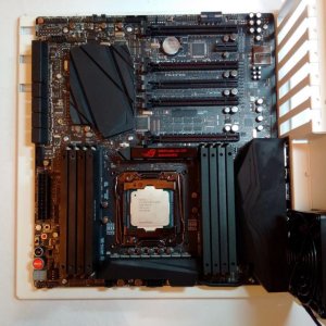
Small update.
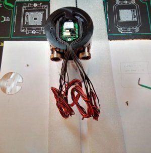
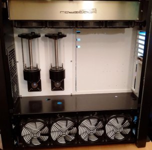
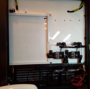
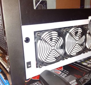
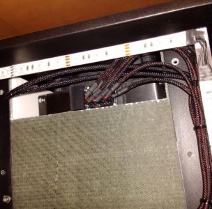
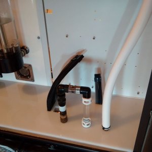
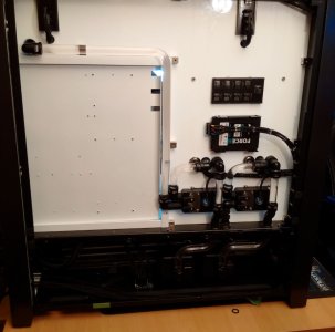
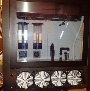
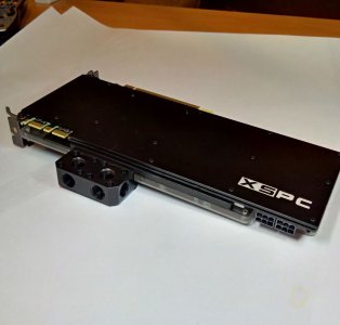
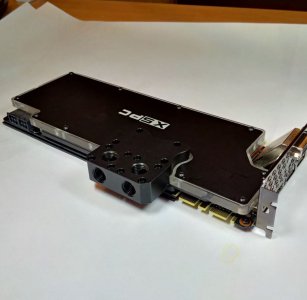
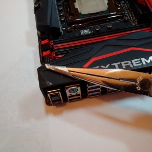
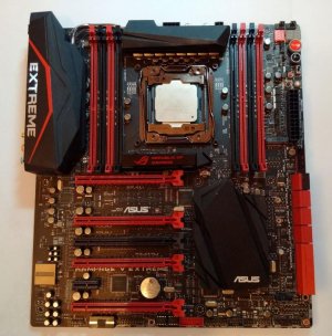
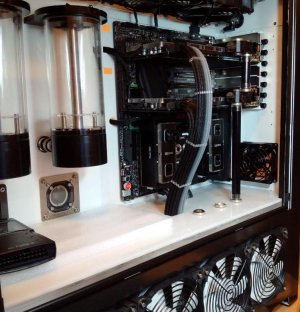
Got all the parts fitted to the motherboard and slid it into the chassis. I felt sick for a while when it looked like I had measured the position of the GPU loop feed from the mid plate wrong but it turned out to be the slide out not being fully home, phew!
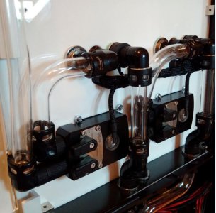
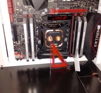
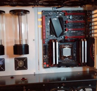
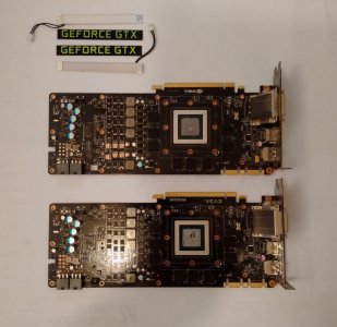
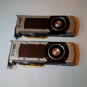
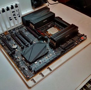
The 2 black pipes are just there to take the weight of the cards off the PCI-E slots the tubing is going to be clear.
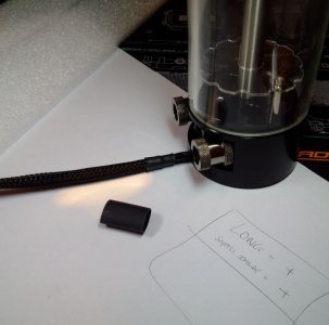
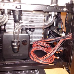
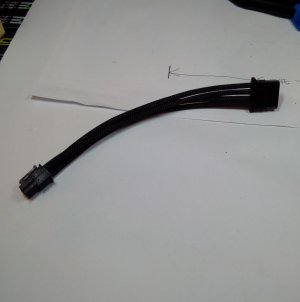
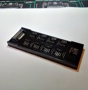
I have scrapped the short extension 24pin cable I made up, it was just not sitting right when the plug was in the mobo socket. The way that cable "fans" out of the mobo into the mid plate is a big feature and needs to be right.
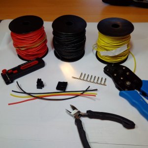
I have looked at the Corsair cable and there is only one 2 wire into one situation so I have decided to make a custom cable straight from the PSU through the mid plate and into the MoBo. The extra length of a cable like this will let me play around with the wires in the bottom chamber to make them sit right in the main chamber.
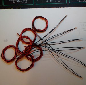
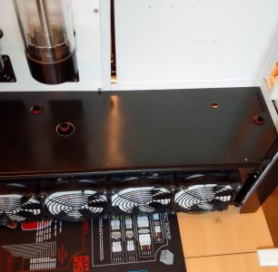
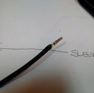
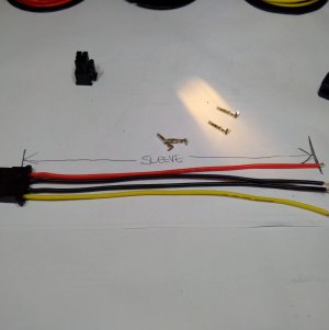
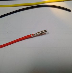
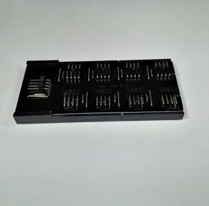
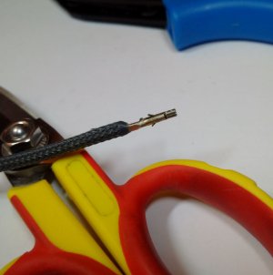
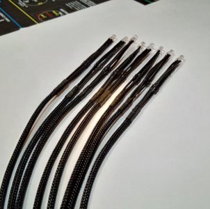
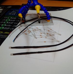
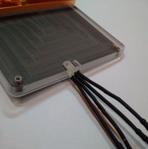
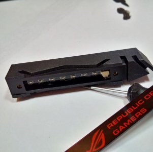
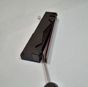
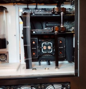
The GPU cables have gone in how I wanted, I just need to cut the other ends to length and fit connectors, same with the 8 RGB LED wires, the 4 pin and 8 pin CPU cables.
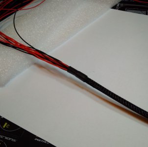

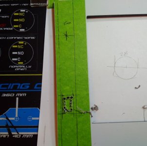
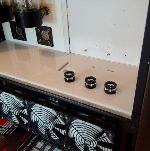
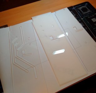
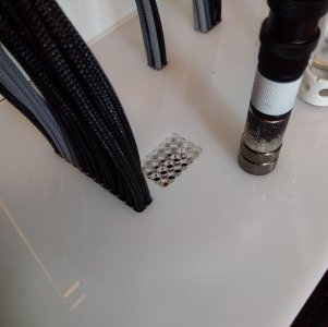
 I have to get the CPU loop flow and return, the GPU loop flow and 24 wires from the main connector which I want to have in 24 individual holes routed in the plate so its a bit of a head scratcher.
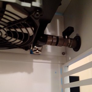
") Your current build is pretty incredible too, so original and that raised roof is the crowning glory.
Your current build is pretty incredible too, so original and that raised roof is the crowning glory.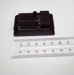

 but at least it is "only" on a gaming rig and not my main work pc. I suppose this is the risk you take with new products?