Blade Runner
New member
"D00D" - Corsair 900D Reverse
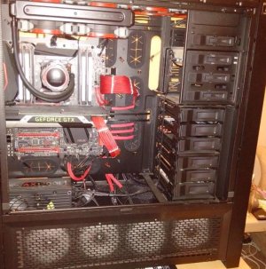
“DOOD” is my next project, it’s my sons 900D which I have managed to pry off him (By installing his system in a work bench). This was my first ever build about 15 months ago, looking at it now it is pretty shabby, especially the cable management.
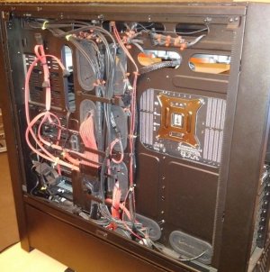
The cable “management” consisting of stuffing cables out of sight or tying them in loops and cable lacing with what looks like white rope. It was searching for a cable lacing guide for that build that made me find this forum and TTLs excellent reviews and I was hooked J
The main reason for this build, apart from keeping me busy while I still can’t do anything heavy manual (I have a week of tests at Papworth in December, which if all good, will mean I will be okay renovating the house again), the layout of my sons room/ desk means that a pc with a normal window on the left does not really work.
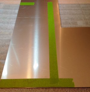
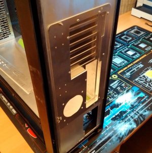
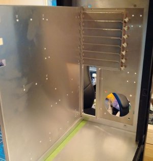
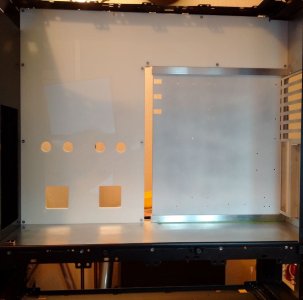
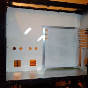
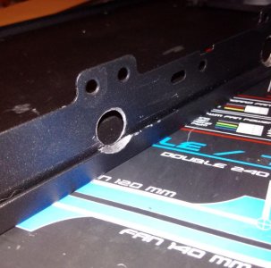
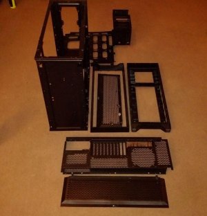
The plan therefore is to build this case in reverse style or as I call it upside down. This will involve quite a lot of custom metal work, by hand and custom acrylic by CNC and lots of head scratching and doing things several times until I get it just right.
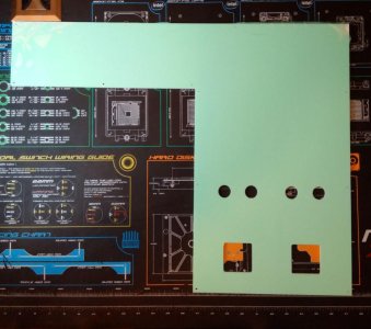
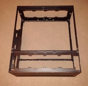
I am going to fabricate a new motherboard tray from either Acrylic or aluminium which will mean it will be nice and clean with only enough cable holes in the right places. I am also going to move it forward toward the window.
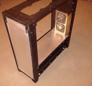
The cable space behind the standard mobo tray is very narrow for such a large case, as far as I can tell I think it has been made that way to allow the mounting of the HDD bays fully in front of it. As I am not having any HDDs in this build that will not matter.
The items that will be getting reinstalled from the original build are the following:
· ASUS Rampage V Extreme MoBo
· 5930K CPU
· GTX 980 GPU
· Corsair AX1200i PSU
· Corsair Dominator Platinum 16GB 2666 RAM
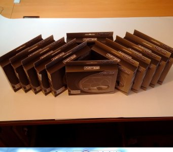
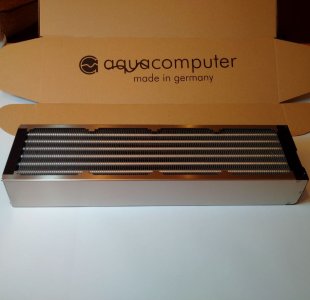
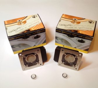
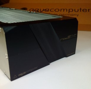
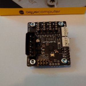
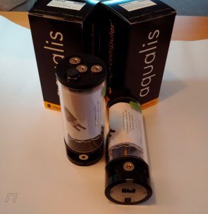
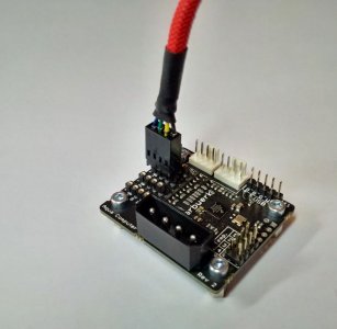
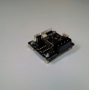
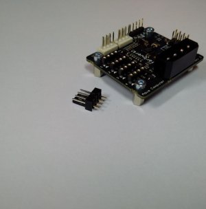
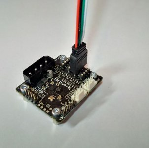
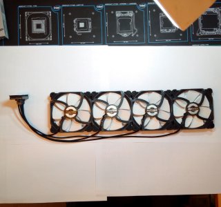
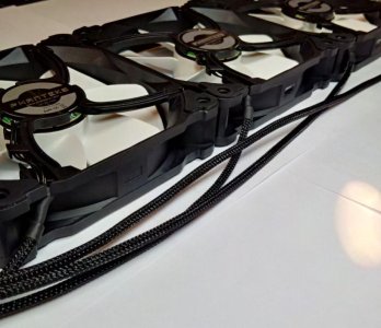
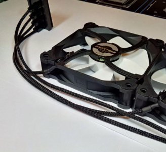
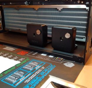
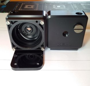
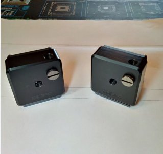
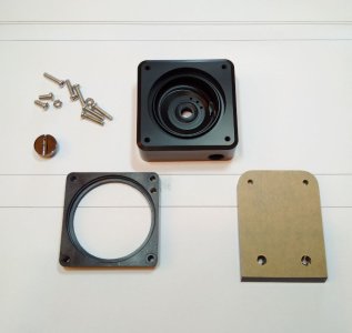
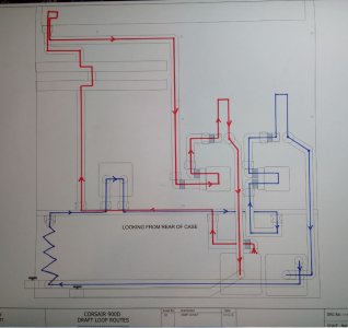
The plan is for the RAM to get another 16GB kit and I’ll add another GTX 980. It’s going to be water-cooled with dual loops and as much radiator length as I can fit without making it look cluttered. The Pumps will be AQ D5s with the USB and Aquabus interface mounted in XSPC acetal pump tops which I just love to look of.
I have managed to locate 2 of these tops but I think they may have been discontinued as there is a newer more square type available. The main colours are planned to be black and white but this may change. In many ways it is going to be like my STH10 in layout, reversed.
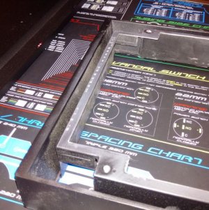
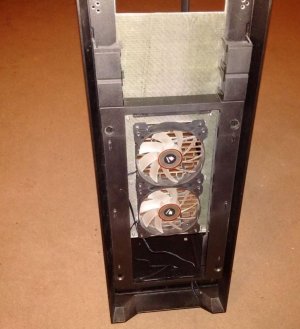
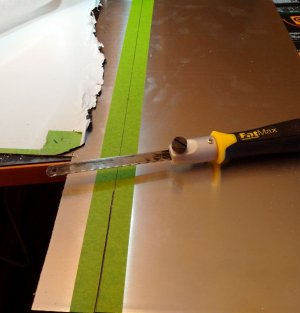
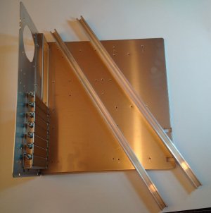
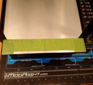
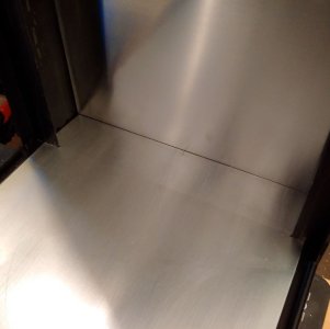
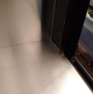
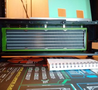
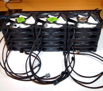
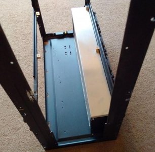
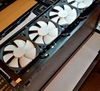
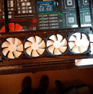
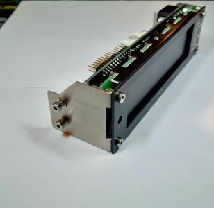
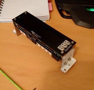
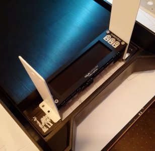
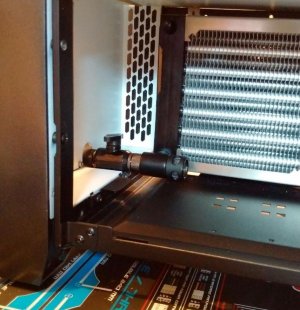
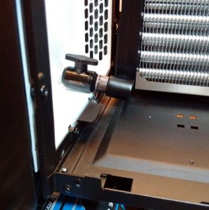
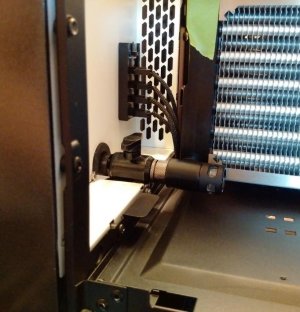
Here are a few before and after pics of the disassembly.
PS. If you are wondering, the builds name, “D00D” or "d00D" (pronounced dude) is 900D upside down; well it’s not really, as my son pointed out – "it’s 900D flipped 180 degrees on its lower axis” but that does not roll off the tongue quite so easily.. J
“DOOD” is my next project, it’s my sons 900D which I have managed to pry off him (By installing his system in a work bench). This was my first ever build about 15 months ago, looking at it now it is pretty shabby, especially the cable management.
The cable “management” consisting of stuffing cables out of sight or tying them in loops and cable lacing with what looks like white rope. It was searching for a cable lacing guide for that build that made me find this forum and TTLs excellent reviews and I was hooked J
The main reason for this build, apart from keeping me busy while I still can’t do anything heavy manual (I have a week of tests at Papworth in December, which if all good, will mean I will be okay renovating the house again), the layout of my sons room/ desk means that a pc with a normal window on the left does not really work.
The plan therefore is to build this case in reverse style or as I call it upside down. This will involve quite a lot of custom metal work, by hand and custom acrylic by CNC and lots of head scratching and doing things several times until I get it just right.
I am going to fabricate a new motherboard tray from either Acrylic or aluminium which will mean it will be nice and clean with only enough cable holes in the right places. I am also going to move it forward toward the window.
The cable space behind the standard mobo tray is very narrow for such a large case, as far as I can tell I think it has been made that way to allow the mounting of the HDD bays fully in front of it. As I am not having any HDDs in this build that will not matter.
The items that will be getting reinstalled from the original build are the following:
· ASUS Rampage V Extreme MoBo
· 5930K CPU
· GTX 980 GPU
· Corsair AX1200i PSU
· Corsair Dominator Platinum 16GB 2666 RAM
The plan is for the RAM to get another 16GB kit and I’ll add another GTX 980. It’s going to be water-cooled with dual loops and as much radiator length as I can fit without making it look cluttered. The Pumps will be AQ D5s with the USB and Aquabus interface mounted in XSPC acetal pump tops which I just love to look of.
I have managed to locate 2 of these tops but I think they may have been discontinued as there is a newer more square type available. The main colours are planned to be black and white but this may change. In many ways it is going to be like my STH10 in layout, reversed.
Here are a few before and after pics of the disassembly.
PS. If you are wondering, the builds name, “D00D” or "d00D" (pronounced dude) is 900D upside down; well it’s not really, as my son pointed out – "it’s 900D flipped 180 degrees on its lower axis” but that does not roll off the tongue quite so easily.. J
Attachments
Last edited:
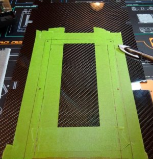
") used the panel next to the mobo as the reservoir
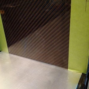
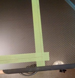
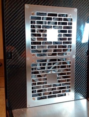
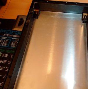
used the panel next to the mobo as the reservoir  Worth it though for the 3D depth you get on the weave of the real carbon fibre, you cant see it in the pictures but it looks really deep and it sort of moves when light hits it from different directions.