CaseLabs STH10

Another case of a little job turning into a big one.........

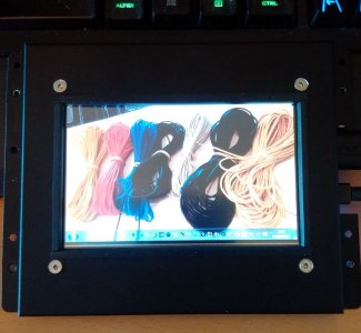
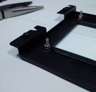
When I tested the monitor I noticed that the touch screen was not working, lots of searching and head scratching later I realised that it was not a driver problem but because I had squashed the screen too much around the edge where I had tightened it against the rubber edge trim.

It was easy to sort out I put 3 nuts on each screw and tightened against them which has left the screen about 1mm clear of the rubber trim all round and working as it should.

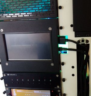
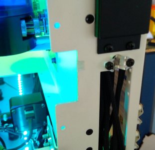
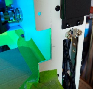
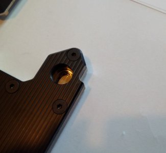
I thought the cut out on the chassis would just need to match the one on the FlexBay cover but after cutting it out and finishing it smooth it turned out that I had measured from the wrong side of the frame and I needed more cut out.

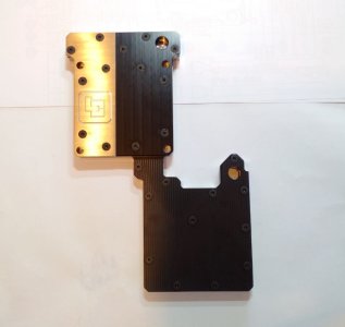
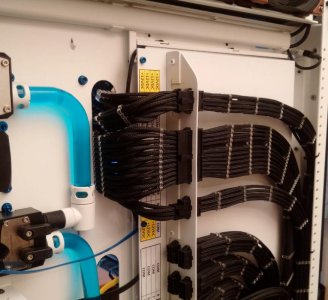
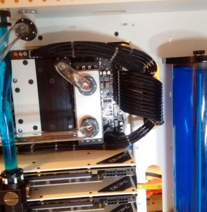
The final result can be seen below, with all the stopping and starting and re-doing of stuff it has took the best part of 5 hours, it just does not look like it!

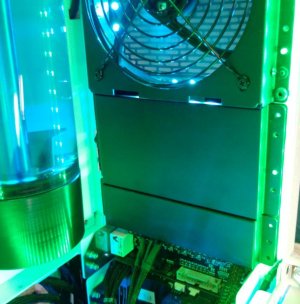
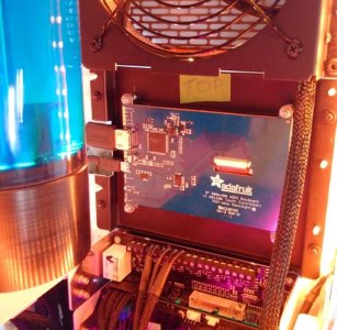
I had always planned on covering the back of the monitor with a spare flex bay cover, I am just a bit undecided on which type. I like the vented type as I think it blends with the fan grills above better but the solid type does hide the monitor fully.

I may end up putting a cover plate behind the vented cover so I have the look of the vented cover with the covering up of the solid one.
 

Attachments

  • Monitor_20.JPG
    Monitor_20.JPG
    86.6 KB · Views: 80
  • Monitor_19.jpg
    Monitor_19.jpg
    81.8 KB · Views: 78
  • Monitor_18.jpg
    Monitor_18.jpg
    90.9 KB · Views: 75
  • Monitor_17.jpg
    Monitor_17.jpg
    91.1 KB · Views: 73
  • Monitor_16.JPG
    Monitor_16.JPG
    94.6 KB · Views: 80
  • Monitor_15.JPG
    Monitor_15.JPG
    73.7 KB · Views: 82
  • Monitor_14.JPG
    Monitor_14.JPG
    56.5 KB · Views: 76
  • Monitor_13.JPG
    Monitor_13.JPG
    78.5 KB · Views: 77
  • Monitor_21.JPG
    Monitor_21.JPG
    50.2 KB · Views: 76
Awesome work, the solid cover works better aesthetically IMHO.

Thanks Davva, I have been looking at this since Sunday and I now have to agree, the solid does look better, the only trouble is that I don't have a 3 slot solid cover, only the 2 slot and 1 slot in the picture.

As this is part of the main chamber I am going to have to make a custom solid cover as even if I got a 3 slot solid from CaseLabs it does not sit flush with the Fan mount above and would look all wrong. (The step back at present is nearly 15mm, a lot more than it looks in the picture)

Another little detail that will take time but that is where the fun is :) as I keep telling myself!:huh:

Good news on the Motherboard water block; it has been posted, so should be here toward the end of the week. I just need to get another PC set up for my work and then I will be able to start taking this one apart for the parts.
 
Another little job tidied up; when I fitted the first back plate to the GPUs I did not fit the little red spacer washers, I miss-read the manual.

It had to come apart to fit the washers so I took the opportunity to replace the thermal paste on the main GPU chip with the new Alphacool Eisschicht 17 W/mk thermal pads that I got a few weeks ago.


I left the RAM and other chips covered with the standard thermal pads that came with the kit; the Alphacool pads are very expensive. This meant I had to use different thicknesses of the Aplhacool pads to make sure the other pads still come into contact with the water block/ back plate. The main pad which touches the GPU is a 0.5mm thick one and the pad on the other side touching the back plate is a 1mm thick type.

I will do the same to the other GPU I have off the PC which will leave only the one left on this machine when I strip this down.
 

Attachments

  • GPU_ThermalPad_6.JPG
    GPU_ThermalPad_6.JPG
    56.3 KB · Views: 74
  • GPU_ThermalPad_5.jpg
    GPU_ThermalPad_5.jpg
    84.3 KB · Views: 74
  • GPU_ThermalPad_4.JPG
    GPU_ThermalPad_4.JPG
    68.7 KB · Views: 67
  • GPU_ThermalPad_3.JPG
    GPU_ThermalPad_3.JPG
    60.6 KB · Views: 82
  • GPU_ThermalPad_2.JPG
    GPU_ThermalPad_2.JPG
    66.6 KB · Views: 72
  • GPU_ThermalPad_1.JPG
    GPU_ThermalPad_1.JPG
    66.4 KB · Views: 67
I had a delivery today from Germany..............The Postman gave me a funny look, the box had "Liquid Extasy" printed on it ;)

Anyway, the packing was very good with plenty of air bags and polystyrene surrounding the block in the middle of the box.

It comes with instructions, fixing screws, thermal pads/ Paste, (To be swapped for Alphacool 17W/mk pads as above) and even 2 small screwdrivers to fit the mounting screws.

It is even better looking in the flesh than I had imagined, a real bit of quality engineering and it weighs nearly 1Kg, so plenty of metal.

The LE branded nickel plate on the left of the block will come off to be painted white with the LE brand picked out in black to match the rest of the build.

I have borrowed a PC to transfer all my work apps to so I will be busy setting that up over this weekend then next week I can strip this PC down to start building the motherboards water cooling system :)
 

Attachments

  • FullCoverWaterBlock_6.JPG
    FullCoverWaterBlock_6.JPG
    61.1 KB · Views: 76
  • FullCoverWaterBlock_5.JPG
    FullCoverWaterBlock_5.JPG
    65.6 KB · Views: 90
  • FullCoverWaterBlock_4.JPG
    FullCoverWaterBlock_4.JPG
    68.4 KB · Views: 79
  • FullCoverWaterBlock_3.JPG
    FullCoverWaterBlock_3.JPG
    48.9 KB · Views: 73
  • FullCoverWaterBlock_2.JPG
    FullCoverWaterBlock_2.JPG
    42.7 KB · Views: 74
  • FullCoverWaterBlock_1.jpg
    FullCoverWaterBlock_1.jpg
    81 KB · Views: 81
Today I wanted to fit the Alphacool Eisschicht 17 W/mk thermal pads to the second GPU, leaving only the one in this machine to do when I take it apart.

All went well until I held the GPU up to the light to see if all the little red washers were still in place and I noticed a gap between the back of the RAM chips thermal pads and the back plate. I did a quick check of the GPU I did the other day and it was the same, no contact between the back plate and the PCB/ Chips.

It was fixed on both GPUs by swapping the pads for thicker ones. I tried the pads that came with the back plate kits and they were the same, they do not touch.

It is not an installation problem either, the way the back plate/ water block has spacers and washers, you are tightening against a hard surface, it is not a case of just not tightening enough to get contact.

The other job was extending the RGB LEDs for the "inner" light hole on the GPU acrylic plate. I staggered the joints so as when they are sleeved you don't get a big bulge in the sleeve as you would if they were all jointed at the same place.

I got most of my work apps up and running on the spare PC which I will be using while I take this one apart. I just have a couple more that need uninstall/ install codes to be able to move them which I will get this week so hopefully I will be able to start work on the water cooling on the mobo next weekend.

ETA. Pictures of the LE full cover water block with white paint finish.
 

Attachments

  • GPU_RGB_Upgrade_4.JPG
    GPU_RGB_Upgrade_4.JPG
    81.5 KB · Views: 69
  • GPU_RGB_Upgrade_3.JPG
    GPU_RGB_Upgrade_3.JPG
    45.1 KB · Views: 63
  • GPU_RGB_Upgrade_2.JPG
    GPU_RGB_Upgrade_2.JPG
    44.8 KB · Views: 72
  • GPU_RGB_Upgrade_1.jpg
    GPU_RGB_Upgrade_1.jpg
    91.9 KB · Views: 70
  • GPU_ThermalPad_7.JPG
    GPU_ThermalPad_7.JPG
    61.4 KB · Views: 61
  • MoBoWaterBlockPainted_1.JPG
    MoBoWaterBlockPainted_1.JPG
    70.2 KB · Views: 70
  • MoBoWaterBlockPainted_2.JPG
    MoBoWaterBlockPainted_2.JPG
    59.7 KB · Views: 75
Last edited:
Got the power and reset switches fitted and fully wired/ sleeved up tonight. Using an idea I spotted on someone else's build on here (cant remember their name but thanks, it is a much tidier solution) I used two USB2 connectors, super glued together, to make a neat connection between the various wires and the motherboard socket.

I used 2.5mm sleeve for the last 150mm to avoid having to use heat shrink. I super Glued these small sleeves to the wires so hopefully they wont show any inner wire when they fit into the board.

I have been too busy at work to have time to swap over the final apps to my spare PC to allow me to strip this down and start fitting the water blocks. Next week should be ok to make the swap. In the meantime I will continue to tidy up the loose ends, in particular cable tie up neatly all the wires at the rear of the case.
 

Attachments

  • SystemSleeved_5.JPG
    SystemSleeved_5.JPG
    86.2 KB · Views: 67
  • SystemSleeved_4.JPG
    SystemSleeved_4.JPG
    74.4 KB · Views: 66
  • SystemSleeved_2.JPG
    SystemSleeved_2.JPG
    74.4 KB · Views: 72
  • SystemSleeved_1.JPG
    SystemSleeved_1.JPG
    63 KB · Views: 62
Last edited:
I finally got round to painting the pump ends this weekend; they now blend with the rest of the build, yellow was just not right ;)
 

Attachments

  • PumpPaint_4.jpg
    PumpPaint_4.jpg
    92.9 KB · Views: 77
  • PumpPaint_3.jpg
    PumpPaint_3.jpg
    79.5 KB · Views: 61
  • PumpPaint_2.JPG
    PumpPaint_2.JPG
    70.2 KB · Views: 63
  • PumpPaint_1.JPG
    PumpPaint_1.JPG
    69.6 KB · Views: 61
I got all my work apps up and running on my spare PC today so this evening I started stripping down the X99 E-WS.

First thing done was the installation of the water block on the last GPU which went really well; it should have, I have had the other 2 apart 2 or 3 times each to change things so I am well practiced.......................:huh:

I then stripped off the heat sinks from the motherboard and cleaned it up ready to fit the main water block tomorrow.
 

Attachments

  • MotherboardStrip&BuildWet_10.jpg
    MotherboardStrip&BuildWet_10.jpg
    94.6 KB · Views: 68
  • MotherboardStrip&BuildWet_9.jpg
    MotherboardStrip&BuildWet_9.jpg
    93.1 KB · Views: 81
  • MotherboardStrip&BuildWet_8.JPG
    MotherboardStrip&BuildWet_8.JPG
    59.6 KB · Views: 67
  • MotherboardStrip&BuildWet_7.JPG
    MotherboardStrip&BuildWet_7.JPG
    92.8 KB · Views: 61
  • MotherboardStrip&BuildWet_6.jpg
    MotherboardStrip&BuildWet_6.jpg
    82.1 KB · Views: 63
  • MotherboardStrip&BuildWet_5.jpg
    MotherboardStrip&BuildWet_5.jpg
    87.6 KB · Views: 81
  • MotherboardStrip&BuildWet_4.jpg
    MotherboardStrip&BuildWet_4.jpg
    86.4 KB · Views: 63
  • MotherboardStrip&BuildWet_3.jpg
    MotherboardStrip&BuildWet_3.jpg
    92.6 KB · Views: 71
  • MotherboardStrip&BuildWet_2.jpg
    MotherboardStrip&BuildWet_2.jpg
    95.5 KB · Views: 82
  • MotherboardStrip&BuildWet_1.jpg
    MotherboardStrip&BuildWet_1.jpg
    86.5 KB · Views: 68
:drool: I haven't drooled like this since I was a child. :drool:

Great craftsmanship Blade! Keep the work going!

Thanks mecha :)

Just a quick update, I got the main water blocks installed today. Going to start bending tubes now which may take a while.

I have had to order a couple more Monsoon 90 degrees rotarys; there is not enough clearance above the top GPU back plate on the mobo inlet to use either one of the Chaingun or the Free Centre fittings.

I am having to get out of that area with a 90 degree bend and a rotary. As it turns out this will work nicer with the M.2 SSD water block, everything lines up well and it will let me light up that pipe run with another RGB LED light port rotary.

ETA. Two pipes made and fitted pictures added at bottom.
 

Attachments

  • MotherboardStrip&BuildWet_11.jpg
    MotherboardStrip&BuildWet_11.jpg
    96.5 KB · Views: 66
  • MotherboardStrip&BuildWet_12.jpg
    MotherboardStrip&BuildWet_12.jpg
    96.4 KB · Views: 72
  • MotherboardStrip&BuildWet_13.jpg
    MotherboardStrip&BuildWet_13.jpg
    92.1 KB · Views: 81
  • MotherboardStrip&BuildWet_15.jpg
    MotherboardStrip&BuildWet_15.jpg
    88 KB · Views: 71
  • MotherboardStrip&BuildWet_14.jpg
    MotherboardStrip&BuildWet_14.jpg
    86.5 KB · Views: 71
  • MotherboardStrip&BuildWet_16.jpg
    MotherboardStrip&BuildWet_16.jpg
    85.6 KB · Views: 73
Last edited:
Um, any reason why you're using what looks like a thermal pad on both your CPU and GPU core instead of proper paste?
 
Um, any reason why you're using what looks like a thermal pad on both your CPU and GPU core instead of proper paste?

They are Alphacools new 17W/mk rated thermal pads which are supposed to be better than most paste. They should be at about £90 for a 100mm x 100mm piece!

I looked at the W/mk ratings of lots of thermal pastes and there were very few which had a higher thermal conductivity than these pads, I will just have to see how they work. If they don't I will swap them out but I like the idea of pads rather than paste as you know you are getting full coverage right up to the corners of the chips.

wow, this is a really nice logg to follow! looking good and I think it's going to look freaking awsome when finished!"

Thanks Rod :)
 
Last edited:
I got the GPU loop finished and have opened the valves to leak test it, so far so good. I am now waiting on the Monsoon rotarys to finish the CPU loop which should be here for the weekend.

I also painted the RAM blocks face plates white to match the GPU back plates, I think it looks better (better still when I make up some XSPC stickers) but I can change it back as I painted the reverse and left the fronts still black with the XSPC logo.
 

Attachments

  • MotherboardStrip&BuildWet_17.jpg
    MotherboardStrip&BuildWet_17.jpg
    89.1 KB · Views: 69
The monsoon rotarys did not turn up so I have started on the cables to the motherboard. I had made the 24 wire up before but the others have been made today.

This board takes 2 x 8 pin CPU connectors and a 6 pin PCI-e auxiliary on top of the 24 pin main connector so quite a lot of cables to try and keep tidy.

I used a full scale sketch of the relative positions of the connectors to each other, to help with getting the individual wire lengths correct.

This just leaves the rest of the RGB led lights to finish and the GPU cables, the latter will take a bit of time as they are the most visible in the case and need to sit right.
 

Attachments

  • CablesToMobo_1.JPG
    CablesToMobo_1.JPG
    33.8 KB · Views: 63
  • CablesToMobo_2.JPG
    CablesToMobo_2.JPG
    94.1 KB · Views: 66
  • CablesToMobo_3.jpg
    CablesToMobo_3.jpg
    86.3 KB · Views: 71
  • CablesToMobo_4.jpg
    CablesToMobo_4.jpg
    87.8 KB · Views: 64
It will be interesting to see the performance of those thermal pads! I love the idea of pads versus paste, just to eliminate any application-based issues.

Looking good as usual Blade!
 
It will be interesting to see the performance of those thermal pads! I love the idea of pads versus paste, just to eliminate any application-based issues.

Looking good as usual Blade!

Thanks again Bart, yes the pads performance will be interesting; from what I have read on the interweb, mostly in German so I probably miss read it :D
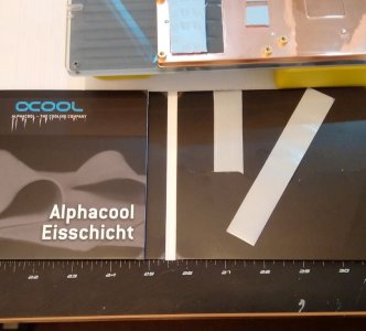
, was that they were good for CPU and GPU use but not high power GPUs.

I read that as being okay for my 970s which will not be overclocked and my 5820K which will, but has run very stable, with a 4.3 Ghz OC and cooled by an all in one cooler.

I know they are new but apparently the tech behind them is quite established, if you Google Sarcon XR-m there is quite a lot of info'

I really do hope they work, I don't really want to have to strip this board down that soon! :eek:

I find paste a bit hit and miss with the application and coverage, for example when I took the CPU water block off the 5820k from its previous home the pre applied paste on the all in one cooler was only covering a circle on the back of the CPU chip, lots of bare metal that hopefully these pads will overcome.
 
Last edited:
Back
Top