CaseLabs STH10

They are Alphacools new 17W/mk rated thermal pads which are supposed to be better than most paste. They should be at about £90 for a 100mm x 100mm piece!

I looked at the W/mk ratings of lots of thermal pastes and there were very few which had a higher thermal conductivity than these pads, I will just have to see how they work. If they don't I will swap them out but I like the idea of pads rather than paste as you know you are getting full coverage right up to the corners of the chips.

Aren't the pads ultimately thicker than paste though? It does sound intriguing.

JR
 
Aren't the pads ultimately thicker than paste though? It does sound intriguing.

JR

They are thicker, in my case the pads on the main CPU & GPU chips are 0.5mm. I'm not sure how that will effect it, once the pad is hot all the way through I think it wont make any difference?

Like a tube full of marbles, once it is full, if you put one in at one end, one will fall out instantly at the other end. The actual marbles are moving slowly but the effect is instant?

Any thermal dynamicists out there? :)

The thickness will have a huge impact on the heat transfer. The figure you quoted 17W/mk comes from W*m/K*m^2 or...

Heat Transfer (Watts) * Thickness (meters) / Temperature difference (Kelvin) * Area (meters squared)

So it is infact an expression for the heat transferred through a material for a given drop in temperature per unit area proportional to it's thickness. If the pad was hypothetically 5x thinner the heat transfer would be 5x greater. Or more critically if it was thicker the drop in temperature would be greater. I know for a moment that sounds good but it isn't, in order to transfer the most heat possible you want the temperature to remain high. While the pads may have superior conductivity their thickness will more than likely make up for that gain.


Paste and pads have a very different purpose. Paste is intended to smooth imperfections between "rough" surfaces and make up for very slight discrepancies in alignment. Pads fill a gap between two surfaces, generally where heat transfer is less critical. Their roles should never really be reversed. Also using that unit to compare paste with pads isn't appropriate as paste shouldn't have a thickness at all. It's good for comparing two pads of the same thickness, but that's about it.

I think your use of pads will still work to an extent but it definitely won't be better than paste, price doesn't come into it's effectiveness. I would be concerned that using a pad on the core would effect the tolerances of the rest of the block or bend the PCB in a very undesirable way. The higher rated pads are often harder too exaggerating that issue.


If you want my opinion then use your fancy pads where the GPU block originally had 0.5mm pads, 1mm where it had 1mm and a small amount of non-conductive paste on the core. Just a small pea in the center works reliably for me. As much as I would like to see how the pad method goes, I really wouldn't want you to pull your loop apart just to find out.

Best thing would be to find another system/board, get a D15 or nice air cooler and pitch the pads against paste in a fair and conclusive environment.

JR

This is pretty much exactly what I was going to post when I came back, but JR beat me to it. :)
 
I have used different thicknesses of pads to avoid any bending, 0.5 on chips that would normally have paste and 1.0 or 1.5 on the chips that normally have pads.

I don't understand the first bit though JR, "Heat Transfer (Watts) * Thickness (meters) / Temperature difference (Kelvin) * Area (meters squared)"

The pads are available in 3 thicknesses, 0.5, 1.0 and 1.5mm thickness in this case all 17W/mk - does that mean that these three thicknesses of 17W/mk pads are made from different formulations? Or am I not getting my head round it? Its early and the coffee has not kicked in yet..........

ETA Is the 17W/mk bit a measure of the "speed" which the heat transfers through the pad?

ETA(2)I really do hope they work, it will be a right pain to have to take this apart after just getting it built up :eek: I only went down this route because I read of problems with getting this full cover mobo water block to sit right on the CPU and the Plex chips because of its considerable size.
 
Last edited:
I have used different thicknesses of pads to avoid any bending, 0.5 on chips that would normally have paste and 1.0 or 1.5 on the chips that normally have pads.

I don't understand the first bit though JR, "Heat Transfer (Watts) * Thickness (meters) / Temperature difference (Kelvin) * Area (meters squared)"

The pads are available in 3 thicknesses, 0.5, 1.0 and 1.5mm thickness in this case all 17W/mk - does that mean that these three thicknesses of 17W/mk pads are made from different formulations? Or am I not getting my head round it? Its early and the coffee has not kicked in yet..........

ETA Is the 17W/mk bit a measure of the "speed" which the heat transfers through the pad?

ETA(2)I really do hope they work, it will be a right pain to have to take this apart after just getting it built up :eek: I only went down this route because I read of problems with getting this full cover mobo water block to sit right on the CPU and the Plex chips because of its considerable size.

No it isn't the speed at all, if it was the unit would contain time. It describes how much heat can pass through a material when the temperature drops a certain amount from one side to the other. In most practical applications it's easier to think of that the other way around. If the heat passing through it is X then the temperature on the cooling side will be a certain amount lower than the other side. In an ideal world the surface temperature would be the same on both sides, that would be perfect conductivity.

BUT it's also per unit thickness, so if the thickness increases so will the drop in temperature. It describes only the conductivity of the material NOT the conductivity of a piece Xmm thick.


Maybe seeing some numbers will help you understand. So firstly for the pads the following equation we know is equal to 17. The heat load from card we will assume is constant at it's maximum of 150W, thickness is 0.0005m and the area is approximately 0.009m^2. Temparature difference is the unknown, lets call it d

Heat Transfer (Watts) * Thickness (meters) / Temperature difference (Kelvin) * Area (meters squared)

17 = 150*0.0005/d*0.009

d = 0.49°K


If the pad was thinner but the W/mk was lower, let say it's rubbish and only manages 5 but it's 0.1mm thick then it will perform better.

5 = 150*0.0001/d*0.009

d = 0.33°K


Using that figure to compare the performance of pads and paste isn't really a fair representation of the entire situation. Paste shouldn't really have a thickness at all and just having a high conductivity is not it's only function. It's not about how well heat can flow through the paste but how it can improve the efficiency of transfer between two imperfect surfaces. Some waterblock manufacturers recommend applying paste to the pads to improve the efficiency of the interface between component and pad. I'm sure you can appreciate why it would be counter-productive to paste both sides of a pad inbetween two nice big flat surfaces that don't have a gap inbetween them.

Copper is even more conductive than the fancy pad, 401 W/mk, but putting a piece of that on your GPU wouldn't help anything. Obviously the pad will probably form to surface imperfections better than copper, but paste would be even better.


Having said ALL of those things, I still think it will work. But it's definitely not a better solution to the actual problem.

JR
 
Last edited:
Thanks JR, I understand now :) Its a more civilised time of the day for one thing but the figures made it much clearer.

Its just a case of fingers crossed it will work now, I should know this week when the parts turn up for the last bit of the CPU loop.
 
Last edited:
The 2 monsoon rotarys I needed turned up but one was a 45 degree, not a 90 as needed so while I wait on the replacement I used a 16mm OD rotary so I could get the loop finished.

I have to take apart that part of the loop to install the new M.2 950 PRO when it is delivered at the end of October so I will fit the correct 19mm light port rotary and the RGB light in that pipe from the M.2 Cooler to the Mobo cooler inlet. All the other wires/ cables are fitted including 7 out of a possible 10 sata cables. Since I planned the storage SSDs have come down in price so the 3 slots for HDDs will not likely be used now, just the SSD slots down there if needed. TBH with OneDrive I don't see me needing any more than I have at the moment: Two 256 in raid 0 and a 512 backup on top of the 256 OS M.2

Talking of M.2 Coolers, when it came to fitting my custom cooler I realised that with the change in the loop forced by the 90 degree bend inlet to the mobo water block it was actually neater and probabally more efficient, to use the other part of the Stinger water block set I bought to solder to the copper plate.

I have all the fans just set on minimum speeds and I haven't done any big stress tests on the CPU, just the Asus diagnostics app and the hottest I have seen on Core Temp is about 62 degrees, on idle it sits around 30 degrees.

The 3 GPUs are idle at 28 degrees and I haven't stressed them yet. The biggest improvement has been the M.2 SSD, when I ran Crystal Disk Mark read write tests it would get up to a finger singeing 88 degrees and slow down. It now idles at 30 and even when running the Crystal Disk Mark app it does not go above 45 degrees.

I have a few more bits to finish off before it gets moved to my desk and access into the rear compartment becomes difficult. I should get most of these done this weekend then I need to take some decent pics with a camera which I will post along with a full spec list.

I have now got to get my head around the Aqua suite on the Aqueros to get them to work properly, heat dependant, not just set slow as at present. I did have it running passive and it was idle at 38 Degrees

This is the first time I have had the pedestal side covers on and I am pleased with the "look" The pedestal only comes with vented side panels and I did not like the look of that so I ordered the main case with solid lower chamber covers and swapped the 2 over as they are identical in size.
 

Attachments

  • TowardThe End_1.JPG
    TowardThe End_1.JPG
    92.9 KB · Views: 82
  • TowardThe End_4.jpg
    TowardThe End_4.jpg
    97 KB · Views: 97
  • TowardThe End_5.jpg
    TowardThe End_5.jpg
    93.7 KB · Views: 96
  • M.2_StingerWaterBlock.JPG
    M.2_StingerWaterBlock.JPG
    78.5 KB · Views: 94
  • TowardThe End_6.jpg
    TowardThe End_6.jpg
    87.9 KB · Views: 91
Last edited:
Just a quick update, I have spent most of today getting the Aqua Computer gear all set up to work from the Aqua suite.

The fans are running around the 180-250rpm range and the pumps on 50% which has made the whole setup virtually silent :)

The FarbWerks and the Jeak AMPs have also now been set up to some fixed colours, I was going to set them to change colour with water temp but I like the purple colour at the moment.

The Monsoon light port rotary turned up in the post but this one too was a 45 degree plain rotary in a 90 degree light port box - It looks like Monsoon have miss labelled a batch and I have managed to get two from that batch, one from the UK and one from Germany............what are the odds?

The red and green fluid is to match my company's colours, I know it may not be to every ones taste ;)
 

Attachments

  • Farbwerk&JeakRGB_SetUp.jpg
    Farbwerk&JeakRGB_SetUp.jpg
    89.3 KB · Views: 79
  • Farbwerk&JeakRGB_SetUp_1.jpg
    Farbwerk&JeakRGB_SetUp_1.jpg
    88.3 KB · Views: 77
Last edited:
I really like that. Christmas theme much :p

Now you mention it.....Ill stick a snow globe in there and that's the decorations taken care of for this year :D

ETA A Nigh time picture and a couple from the rear chamber before it gets put against the wall.
 

Attachments

  • NightLight.jpg
    NightLight.jpg
    83.2 KB · Views: 210
  • CablesEverywhere.jpg
    CablesEverywhere.jpg
    96.1 KB · Views: 209
  • TwistedSisters.jpg
    TwistedSisters.jpg
    89.1 KB · Views: 200
  • Red&GreenShouldNotBeSeenExceptUpon...a...STH10_2.jpg
    Red&GreenShouldNotBeSeenExceptUpon...a...STH10_2.jpg
    89.5 KB · Views: 228
  • 3GPUsCooled.jpg
    3GPUsCooled.jpg
    90.6 KB · Views: 204
  • RAM_Cooled.jpg
    RAM_Cooled.jpg
    86.3 KB · Views: 173
  • PowerToTheGPUs.jpg
    PowerToTheGPUs.jpg
    89.1 KB · Views: 197
  • InfoMonitor.JPG
    InfoMonitor.JPG
    73.2 KB · Views: 211
Last edited:
Came out real nice.


The color scheme of the fluid is very interesting as well. ;)


I'm usually not a fan of cable combs that you can see, but having that many and spaced out like you do actually gives a look I like, nice job on that.
 
I would like to know what the temps are for cpu and gpu at 100% load for delta temps. BUT with all fans at 100%.

Looks great though! The custom sleavings are just gold!
 
Came out real nice.


The color scheme of the fluid is very interesting as well. ;)


I'm usually not a fan of cable combs that you can see, but having that many and spaced out like you do actually gives a look I like, nice job on that.

Thanks Sinnedone, I am getting used to the fluid but the red was just not UV enough so I have some more to play with when I have some time :p

I would like to know what the temps are for cpu and gpu at 100% load for delta temps. BUT with all fans at 100%.

Looks great though! The custom sleavings are just gold!

I'm not really into that type of thing :cool: 
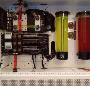
but I will try it when I get some time over the next couple of weeks or so. It will be very loud, 21 Noctuas at 2000rpm and 3 at 3000rpm makes a bit of a din.....What do you recommend to stress the CPU/ GPUs?

One of the cleanest CaseLabs STH10 builds

Thank you, you do a pretty mean build yourself.

I'll bet a year could be spent checking this build out. Great job Mr. Blade Runner.

Thank you too for the kind words.

I will get round to listing the full spec, its a bit different to what I planned at the start, it sort of evolved and I have also kept a list of all the little bits and bobs you need to buy to get the job finished.

Its quite an eye opener, you tend to focus on the big ticket items when costing up a build like this but it is scary how much the little things add up to.
 
Here is the final spec list along with the list of parts I kept as I ordered stuff, as I said its quite an eye opener, lots and lots of little bits that you don't really think about when you start planning something like this.

Asus X 99-E WS
Intel i7-5820K @ 4.6GHz overclock by the ASUS AI utility
G.Skill Ripjaws4 2400MHz 64GB
Samsung 3D 850 PRO SSD 512GB
2nr Samsung 3D 850 PRO SSD 256GB
Samsung SM951 M.2 SSD OS DRIVE (950 PRO 512GB on order to replace this)
3 nr OCUK Reference GTX 970's
WINDOWS 7 PRO (to be upgraded to 10 when the new OS SSD is installed)

The long list of other stuff in no particular order.....:mellow: (Excuse the all caps in places, it was typed as I ordered stuff onto a spread sheet; presentation was not a top priority, it was to ensure stuff was delivered)

2 AQUA COMPUTER FILTERS
48 MONSOON HARDLINE FITTINGS
2 FILL PORTS
2 BLACK BULKHEAD FITTINGS
2 AQUA COMPUTER 300MM RESIVOIRS
6 MONSOON 90 LIGHT PORT ROTARYS
4 MONSOON WHITE LED fittings for light port rotary’s
6 BITSPOWER HIGH FLOW VALVES
20 MONSOON 90 ROTARYS
2 sets pump soft mounts & 2 reservoir top brackets
6 rotary slow 90 bends - Alphacool
3nr XSPC Razor GTX 980 Water blocks and Back plates
2 AQUA COMPUTER XT ULTRA PUMPS
10M of White, Aqua, Navy & Blue sleeve + 10m 18awg black and fan wire E22
8 Bitspower shiny bulkhead through ports
2 Alphacool NeXxXos 560 UT60 radiators
1nr 280 UT60 & 1nr 420 UT45 NexXxos radiators
2 FARBWERK LED CONTROLLERS
FILTER FOR 140.2 FLEXBAY ON STH10
4 Bitspower 22-31mm male to male fittings for back of aqua tube to bulkhead fittings
20 140 Noctua IP 67 IPPC PWM fans 2000rpm
2 140 Noctua IP67 IPPC PWM fans 3000rpm
2 120 Noctua IP67 IPPC PWM fans 3000rpm
2nr UV Glue
Fan connectors 20 male & 20 female and terminals male and female to fit
10 M4 Bolts 10mm Blue Aluminium for mounting res (4 on each bracket)
6 blue accent discs, 6 white G1/4 plugs and 1m long red bending insert
2nr Aquero 6 USB XT Black Passive Heatsinks
5 x 10mm M4 Bolts, 5 washers & 5 nuts Blue Aluminium for mounting res and filters
4 PACKS CLEAR 16MM PIPE 2 TUBES UV GLUE
2 packs of various dia white heat shrink 500mm long so 1m of each diameter
4 XSPC GPU WATERBLOCK CONNECTORS
2NR Aqua computer relay for Aquero 6s
Aqua computer multiswitch black faceplate
Aqua computer multiswitch
2 packs m4 washers (20)
Aqua computer “power adjust 2” faceplate black (for farbwerk)
YELLOW, RED, WHITE AND BLUE 22AWG FAN WIRE 10M of Each colour
10nr sata power connectors plus 15 x 5 (75) crimp terminals to match
3nr Akasa 5.25 hot swap 3.5 & 2.5 drive
2nr JEAK AMPs & 10 rgb leds
BLACK, YELLOW, RED, WHITE AND BLUE 22AWG FAN WIRE 10M PLUS 10M OF BLACK, YELLOW, RED AND BLUE 18AWG WIRE
5 x Mod My Toys 4x4Pin PWM splitter PCB (4 in 1 out)
Stealth Combs and 10 m white sleeve
INTERNAL USB2 EXTENTION CABLES
2nr Aqua computer Real Time Clock push-on modules
2 packs (10) of 12 hole Stealth Combs and 3 packs (15) of 8, 6 and 4 hole stealth combs
6 packs (30) of 4 hole Stealth Combs and 2 packs (10) of 8 and 6 hole stealth combs
Loop thru Molex connectors
2nr AQ Flow sensors
3 flow meter special cables with big "fan" type connector
PSU SUPERFLOWER 1600W TITANIUM
GTX 970 GPU GRADE "B"
Set 4 MNPC Feet
2 fill ports
30nr 4 HOLE STEALTH COMBS
2 monsoon temp sensors for rotary’s
10nr 2 pin DuPont - 10nr 1pin DuPont and 30nr terminals to suit (for temp sensors/ led lights etc.)
SLIM DVD INTERNAL DRIVE FOR ABOVE HOT SWAP
5m rgb led strip
DVD enclosure and 2nr 200mm sata 3 cables
10m telios black sleeve and 800mm 3:1 adhesive lined black heat shrink
5M 6MM BLACK SLEEVE FOR USB CABLES
CABLE TIES AND BLACK STICKY TIE HOLDERS
10M BLACK 8MM SATA SLEEVE
4 RGB CABLES FOR FARBWERKS
40-m 4MM TELIOS BLACK SLEEVE
40m OF RED, YELLOW, BLUE AND 20M BLACK 18AWG SILICONE WIRE
3nr usb2 1m long cables to make up from mobo to splitter in pedestal
4M 6MM BLACK SLEEVE FOR USB CABLES
20 NR 24 HOLE STEALTH COMBS
100 FEMALE ATX PINS AND 10 6PIN GPU CONNECTORS FOR GPUs
Cable ties small 2 x 100 Lindy
5m led strip
10nr ATX tapered female 6 pin sockets and male and female pins for ATX connectors
10nr female 8 pin sockets for gpu and mobo sockets rear of computer
40- M 4MM TELIOS BLACK SLEEVE
100 8 hole stealth combs for 8 gpu cables and 1 CPU cable
60M 4mm TELIOS BLACK SLEEVE
32gb RAM
2nr XSPC RAM water blocks for 8 modules Inc 8 side plates
Liquid Extacy MOBO FULL WATERBLOCK
100 ATX FEMALE PINS AND 40 MALE PINS
16 Monsoon chain gun fittings for mobo chamber
2.8M 1:3 HEATSHRINK ADHESIVE LINED
250 long grip female ATX PINS
80m black 4mm telios sleeve
40M YELLOW 40M BLUE 18AWG SILICON WIRE
256GB M.2 SSD SM951
2 packs 16mm tube
25 12 HOLE STEALTH COMBS
2nr 6nr 4 pin splitters for led bulbs on gpus and ram
120mm fan grill
10m 1.6mm heat shrink
10nr 50 cm sata 6g/s EXTENSION CABLES DE-LOCK
4 DELOCK 500MM EXTENSION SATA CABLES
200 FEMALE ATX PINS 50 MALE ATX PINS
20nr 3 pin male 20nr 4 pin male fan connector’s c/w terminals to match
USB 3 SSD ENCLOSURE WITH USB 3 HUB
ASUS USB 3.1 CARD
FULL SET OF STH10 FILTERS
8 RGB LEDS 600mm long no ends
3nr CORNER XSPC BADGES FOR GPU BLOCKS
12mm heat shrink adhesive 3:1 and 10 LED RGB bulbs common anode
2nr Aqua computer air bleed valves
5" TOUCHSCREEN monitor
1m tiny edge trim for monitor
20m of blue, 10m red, 30m black and 20m yellow silicon 24awg
1nr Monsoon 90 deg rotary white 19mm to fit chain gun fittings for bottom of the case CPU Loop
1nr light port rotary, 1nr plain rotary both 19mm and light port cable/ fitting
3 50cm AKASA super slim sata3 cables fold to fit ssd's

As JR 23 said on the second post of the log, I quote "Whoa that's a lot, a lot of everything :o"

He was spot on with that..............:D and I thank him again for the fan recommendation, that has been priceless.


I ran a stress test as requested (AIDA64), it ran everything at 100% including the RAM at 98% for some reason but it went back to the CPUs normal Clock speed of 3.3GHz so I'm not sure if it s a proper test in the way some like to benchmark.

The temperature was showing at around the 65 degrees mark after about 10 minutes when I turned it off. As this is my main work PC I don't really want to knacker the thing so it will have to do...:D I had the fans on their normal settings ie. very slow, around the 275-300rpm mark.

It is generally running faultlessly and is very quiet with the super slow fans which you cant really hear to be honest. The only sound comes from the pumps which although I have isolated them with soft pump mounts, if I was doing it again I would sit them on some Shoggy Sandwiches.

This is my favourite pic of the build, I will post some final final pics when I have the Samsung 950 PRO M.2 SSD fitted which will alow me to finish the CPU loop with the proper sized light port rotary and another RGB led lighting up the pipe from the M.2 to the mobo block.
 

Attachments

  • Motherboard Chanmber STH10.jpg
    Motherboard Chanmber STH10.jpg
    90.2 KB · Views: 215
Last edited:
I have had the 950 Pro M.2 SSD since the 5th of the month but it has just not been a good time to turn off the STH10 and install it.

Today my hand was forced! When I came back from lunch this afternoon I noticed the level in the GPU loop reservoir had dropped, more than the bit it has been dropping while the final air bubbles migrate to the reservoir.

There was red fluid dripping from the top chamber into the motherboard chamber, thankfully away from the mobo itself but a mess anyway.

I quickly finished what I was doing and got the uninstall code for my main app. Then I drained down the loop and mopped up the mess. Once I established that the leak was coming from the light port insert that the LED fits into I replaced it with a plug, refilled and have had it running for several hours to test with the pumps on full blast.

This is the second light port rotary that has leaked, I looked closely at the plastic screw in insert and it has become very brittle around the lip that holds the o ring. You can break off bits with just light pressure from a fingernail. It looks to me like the heat from the LED has affected the part?

So with my spare PC up and running again with my main apps I thought I may as well fit the 950 PRO.

The loops design came into its own now allowing me to just drain down the motherboard area, to let me remove the heatsink on the existing SM951.

When I had screwed the 950 in place I fired up the pc just to the BIOS to see if it showed up (The SM951 didn't at first and took hours to make it seen in the BIOS and install Windows on it)

The good news is that its there, all ready to go in the morning when I will put Windows 10 on it.

I will put up a disk mark score to see if this NVME is as quick as they are supposed to be once everything is put back together.

The 900D will have to wait until the STH10 is working again, I am so used to the speed of the STH10 that this spare, not a bad PC, an i5 HP seems like something from 10 years ago............
 

Attachments

  • 950Stickered.JPG
    950Stickered.JPG
    65.4 KB · Views: 179
  • 950Boxed.jpg
    950Boxed.jpg
    75 KB · Views: 169
  • OutWithTheOldInWithThe950.JPG
    OutWithTheOldInWithThe950.JPG
    70.5 KB · Views: 201
  • CPU_LoopDrained.jpg
    CPU_LoopDrained.jpg
    86.6 KB · Views: 210
  • 950UnStickered.JPG
    950UnStickered.JPG
    70 KB · Views: 175
Back
Top