mayhem
New member
Build your own SF 4 Controller cheaply .. -=Completed=-
Any damage done to your controller is at you own risk !!!! lol
Build your own SF 4 & Mame Controller cheaply ....
Street fighter will be hitting the PC very soon so im going to show you a cheap ass way of building your very own SF 4 Arcade controller very cheaply. Now if you fancy forking out £99 to a whopping £145 + Vat for a controller from mad cats then please go ahead , how every if you don't just have that sort of money lying around this could possibly be your answer. By the way they say the £145 version is expansive because it uses Sanwa Arcade parts. The Sanwa joystick is £14.00 and Buttons £1.20 each. I will be using Sanwa Parts which i have lying around spare.
This controller can work for the Play station 3 as well as the PC deepening on what junk controller you can lay your hands on (and if you fancy a xbox 360 version get a cheap mad catz wireless controller and do the same and you can have a xbox 360 wireless version). Not only will it be you SF 4 controller but it all so works perfectly for Mame and many emulators out there and just watch you pac man score rocket ...
Some basic tools and Items you will need.
Time to rip apart your cheap ass USB controller.
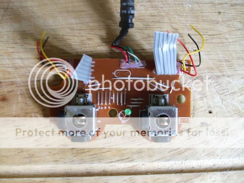
First off i have several Saitek PS2 style controllers that i picked up for 10p because they were to say the least not in a good state so ill be using these for the project. They how do work perfectly fine just there a mess.
So first thing to do is get out you cross head screw driver and remove all the screws and strip these little baby's down because were only after the guts and nothing else.
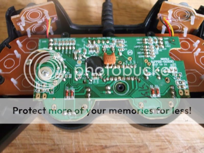
Now one of the good things about these controllers is that the have the buttons named on the PCB's (this is really handy). Now once its fully stripped down take the casing and throw it in the bin.
See all the plastic buttons that are on top of the PCB take them off and throw them in the bin as well as they are not needed any more.
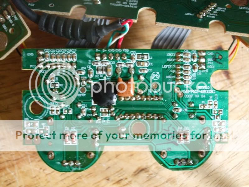
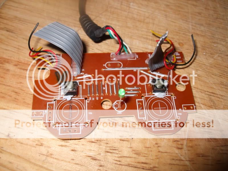
Now you can see there is 4 parts the the controller there is the left and right shoulder pad buttons and then the buttons for the digital and analogue well get you scissors out and chop away the 2 x shoulder button pcb's and the digital pcb as well but make sure you cut right up to there pc's as were going to need all that wire later on.

Now on some forums people like to leave all this in place but me personally think its just a waste of space and there not needed so get rid of them.
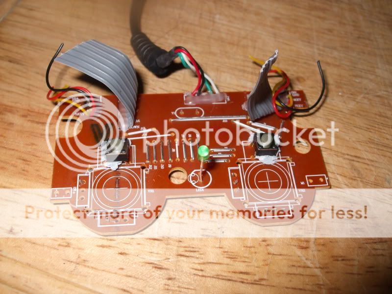
Now you can see there is still the Analogue left and right sticks still left on the pcb's. I have read hundreds of hacks and every one all ways leaves these on but never use them. I know why they do this its because they don't understand how to get around them and when they are removed the controller goes nuts and doesn't work properly in the pc.
So Cut them off lol .. Ill show you how to fix this problem. You can remove them but just wiggling them left and right and they just fall off in you hands ...
Here are a few pics of me ripping them out (yes i did just rip them out). You may need to de solder them but i never do !!!!


Now were still left with the two buttons that when you normally press the Analogue sticks will act as buttons well there not needed so again just rip them out.

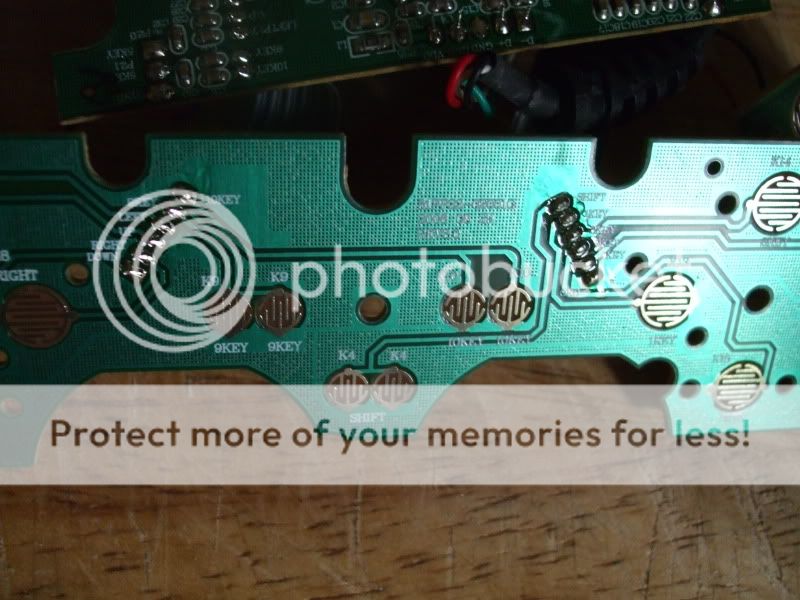
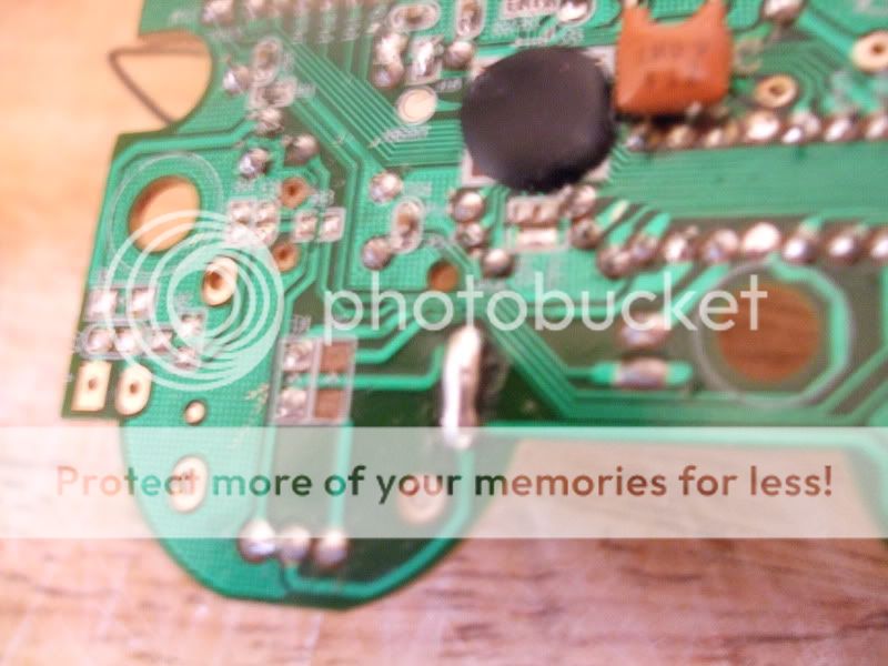
Now you can see were just left with a bare board except for the leads. Now turn over the board and you can see there are 2 diodes were the analogue sticks use to go to, these need removing. To do this just cut them away") so you'll have 4 to remove If you don't this hack will not work properly.
so you'll have 4 to remove If you don't this hack will not work properly.

Now just to the right hand side of the left set of diodes that you have cut out is 3 solder points. These need grounding to another part of the bored. so what you need to do is grab your soldering iron and Connect all 3 lines up and then solder a single wire to a ground point on the controller. Here i done it straight to the usb.

Now if we didn't solder the points and ground them when you connect the controller up to the pc it would be looking for the analogue ports and looking for a signal. well because we have cut them off it would not receive the signal and would go nuts and just either keep chucking a ****ey fit saying controller not connected or will just not load the driver. So by grounding the points you are telling windows and the controller that the analogue sticks are connected and set in a central position") ...
...
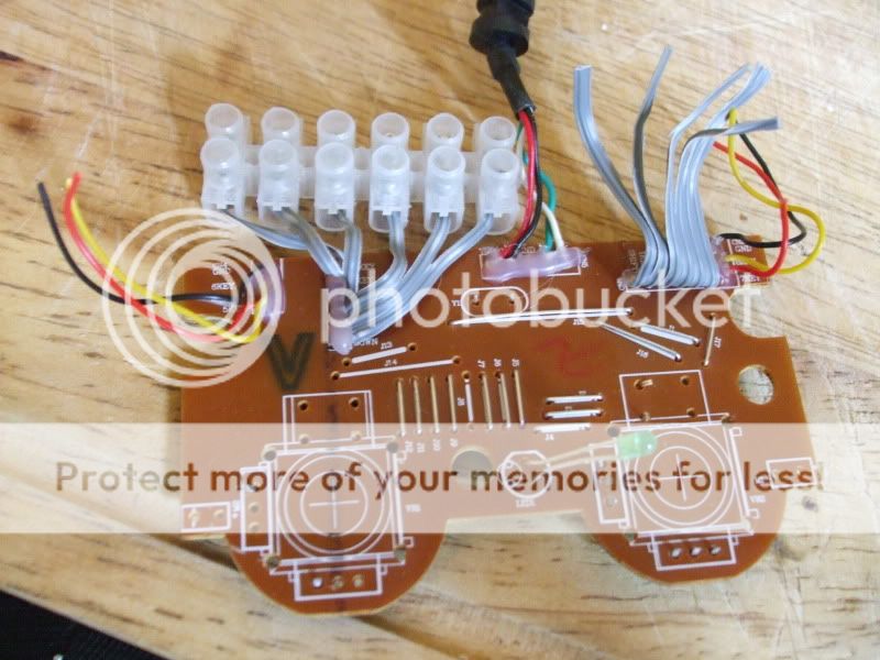
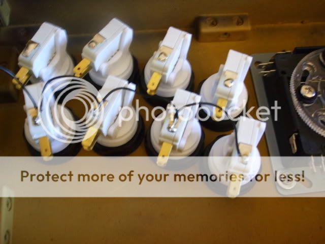
Oky now for the next bit get 17 terminal blocks and screw in the Gray wires you have left over at the top as these are your -
Left
right
up
down
Shift key (change between digital and analogue)
Button 1
Button 2
Button 3
Button 4
Button 10 (start)
Button 9 (select)
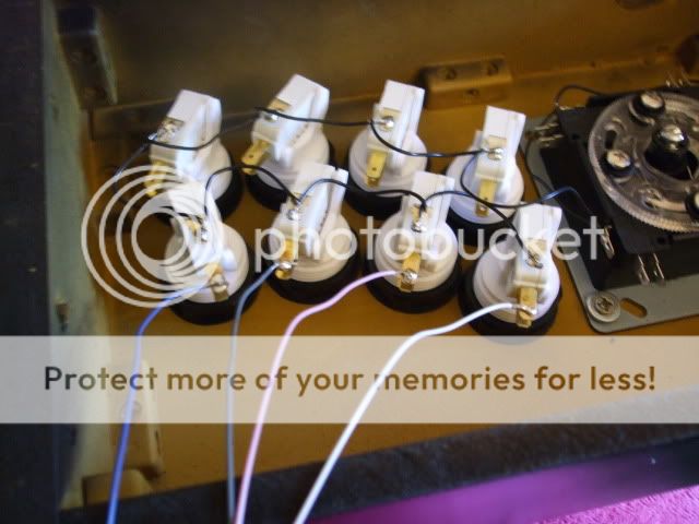
all so wire in the 4 shoulder buttons and the ground so you have a extra 3 plastic blocks on ether side.
Button 5
button 6
Ground
Button 7
Button 8
Ground.
(i have run out in the pics but ill just solder direct to them)

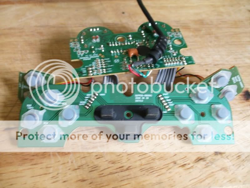
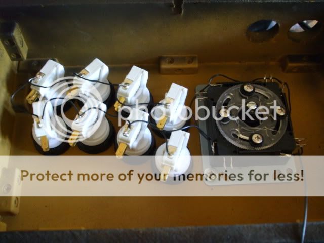
You now has the basis for a cheap ass Controller for a arcade system.
Now what you can do is plug in the controller board (that's what we will call it from now on) to the pc. Go to the joy stick panel and you'll see you controller has appeared. Using a single wire connect it to any ground (GND or black wire ) and touch each connector that you have screwed into place. each time you touch one of the points it will show up as a action on the joy stick control panel. so you can see its working.
Now put you controller board to the side as we wont need it till later on.
building you Arcade stick controller box
All you need to do is make a box to fit every thing in and a top and bottom. Now this can be made of any thing you like. I have seen some one do it in a shoe box which was quite funny but wasn't really going to take a good pounding. So ill show you a nice little MDF one lol ...
First off it would be a good idear for you to print off The arcade lay out of the buttons and stick.
Here is a link to what you need to print for the Street Fighter 4 lay out ->
These images are from slagcoin.com credit belongs to them not me
http://www.slagcoin.com/joystick/layout/horis36_m.png
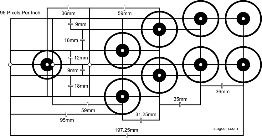
Print it out as landscape and DO NOT STRETCH TO FIT
All so you may what to print out the buttons for the start and select and maybe Shift key .
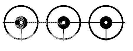
Again do not stretch to fit. if you don't want the shift key just cut it off.
As you can see the layout closely matches the SF 4 £145 arcade stick ...

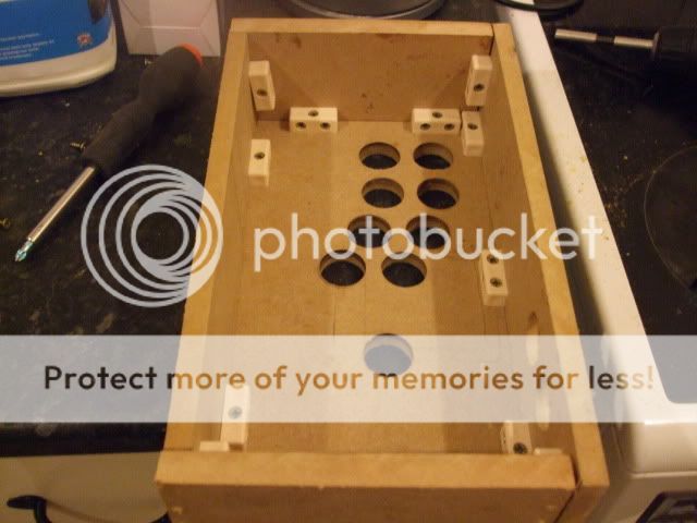
Now what you need to is cut you your top and bottom out of MDF or wood to size. I do recommend you put you hand on the template and test you Right palm as if you playing so that you can cut the box to your own size hand this helps make it better for you self and game play.
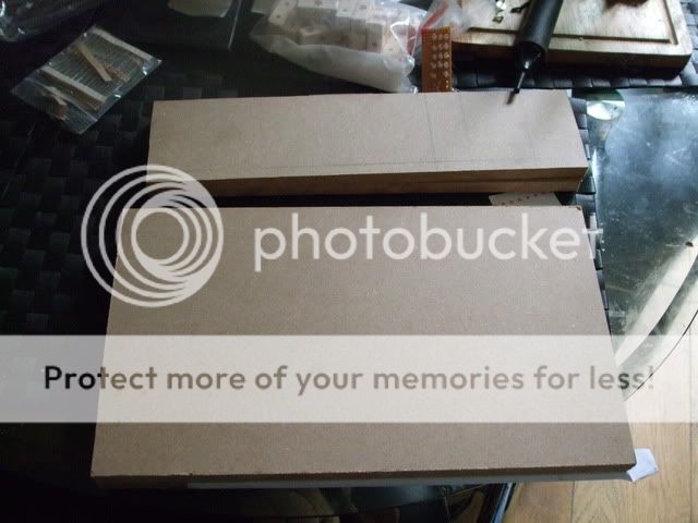
Now once you have the top and bottom part ready place your template on the to the MDF / Wood piece and stick it into place were you feel it best suit your needs.

Once that is ready make sure before you drill the 1 1/8th holes that you have a peace of wood underneath your peace so not to splinter or crack the wood or MDF.

Take your time and dont go to fast.
Once finished you can see the shape take place ..
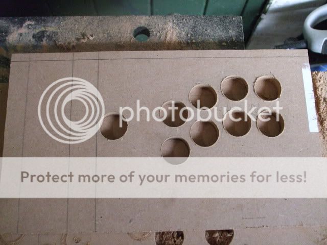
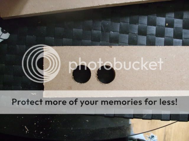
Oky next you need to mark out you start button and select button on the back panel like so and then cut them out.

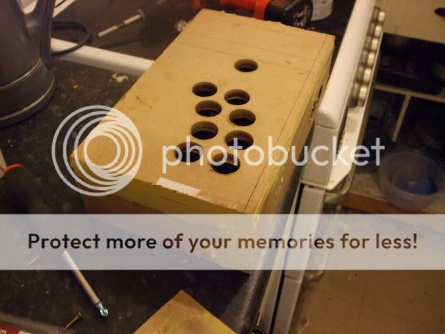
Then start putting you box together. Now if your a good wood worker you'll do a much better job than me im rubbish ...

Dont forget a small hole for the cable to come out (runs off to do that bit lol)
Now My wood working skills are real bad but never the less here is the main part of the box made....
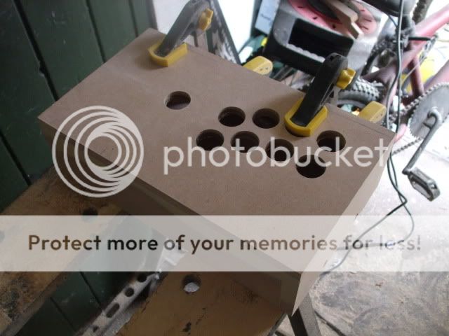
But my wood filling skills rock Not .....

Oky then you need to sand off all that gunk that you have just used to fill your mistakes ...


Here i just routed a edge to clean it off a bit.
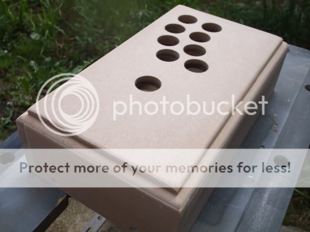
Once that is done and your happy you then need to paint it. Ill be using some spay cans i have left over from another build to do it so no cost is involved.

After a few coats give it another good sanding and you may still need to fill a few gaps. Once that's dried again give it another few coats of primer .. You'll see its starting to take shape.


The inside has been primed and the new layer of Black mat pain has been added. this has 4 layers of paint on after every 2 layers i sanded down with 2000 Grit wet and dry.
Now it needs to be left 24 Hrs before we varnish it.
(first coat of black)
(4th coats)
Curing

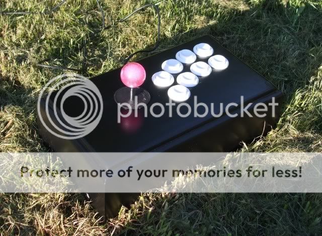
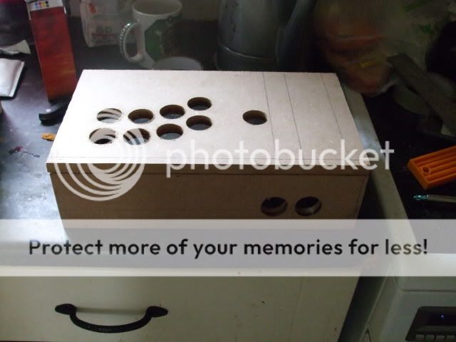
Just a test pic of the button placement ...
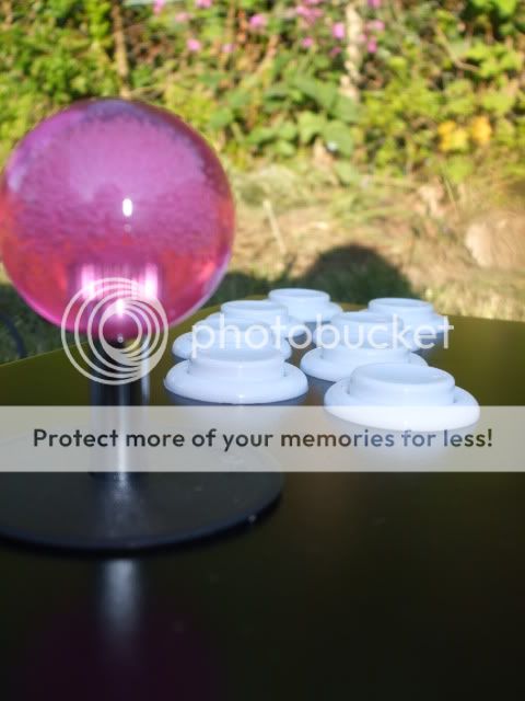
These were ordered from gremlin on Thursday and they are happ's with cherry micro switches giving a very fast response time and a nice firm click sound. Very happy with them.

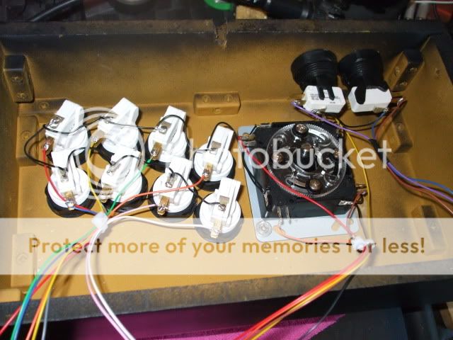
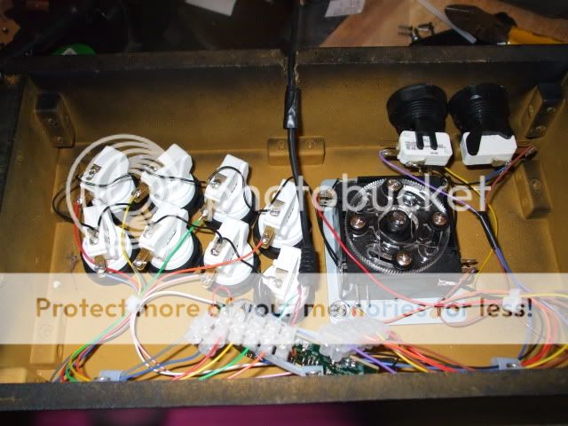
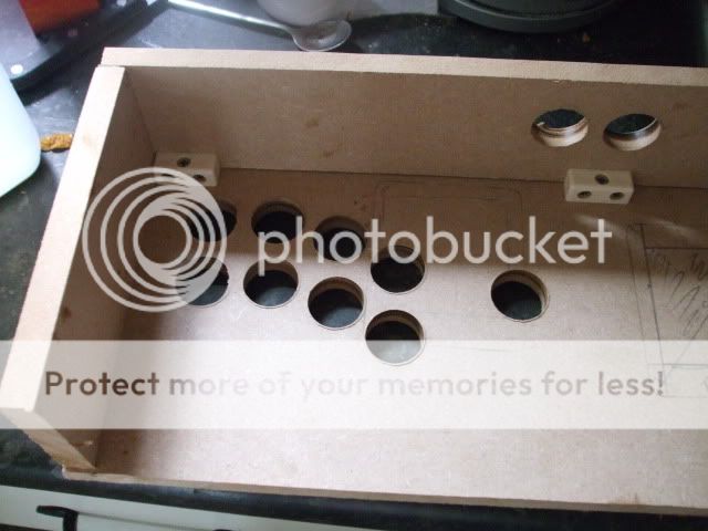
Oky once you have varnished your box you need to let it dry. Then once that is done throw in you buttons and your joy stick and then we need to start putting together the pad pcb that we made earlier on.


Wiring UP time
Now this is How to lay out your wiring and connect up all you buttons a joy sticks.
Im going to show you first the basics of how all this work because it is rely simple to understand and any one can make ther own Arcade stick and it is not difficult.
First off we start with how a switch works.
Here we have a Micro Switch

When Button A is not pressed It Makes a Contact between B and D
when Button A is Pressed It makes a Contact between C and D
So we are going to wire UP Just C and D
Now To make wiring Up easy what we need to do is wire up all the D's in 1 Go to a ground Point on the Controller PCB.
Then we need to wire up all the C to buttons 1,2,3,4,5,6,7 ect
So that when you press a button or move the stick it makes a contact telling to computer what actions you are doing.
Here is a simple to understand diagram of how this all goes together.

So here the ground wire being started on buttons 5,6,7,8 now you dont have to solder you can use Spade connectors instead so that you can disconnect them if your not happy. But im a cheap ass so ill just use solder instead.
Then we go to 4, 3, 2, 1, up, down , left and right .. Ill do the start and select button later on.
Next we have the second wire being soldered to each button in the same order as we just did the ground wire.
Now there all done

Any damage done to your controller is at you own risk !!!! lol
Build your own SF 4 & Mame Controller cheaply ....
First off trusted and respect arcade part dealer if you what to buy new ->
http://www.gremlinsolutions.co.uk/
http://www.ultimarc.com/
(i use them both there real good and Ultimarc is my sponsor for my other project if you do by off them say about c-macc's
Street fighter will be hitting the PC very soon so im going to show you a cheap ass way of building your very own SF 4 Arcade controller very cheaply. Now if you fancy forking out £99 to a whopping £145 + Vat for a controller from mad cats then please go ahead , how every if you don't just have that sort of money lying around this could possibly be your answer. By the way they say the £145 version is expansive because it uses Sanwa Arcade parts. The Sanwa joystick is £14.00 and Buttons £1.20 each. I will be using Sanwa Parts which i have lying around spare.
This controller can work for the Play station 3 as well as the PC deepening on what junk controller you can lay your hands on (and if you fancy a xbox 360 version get a cheap mad catz wireless controller and do the same and you can have a xbox 360 wireless version). Not only will it be you SF 4 controller but it all so works perfectly for Mame and many emulators out there and just watch you pac man score rocket ...
Some basic tools and Items you will need.
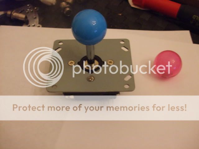
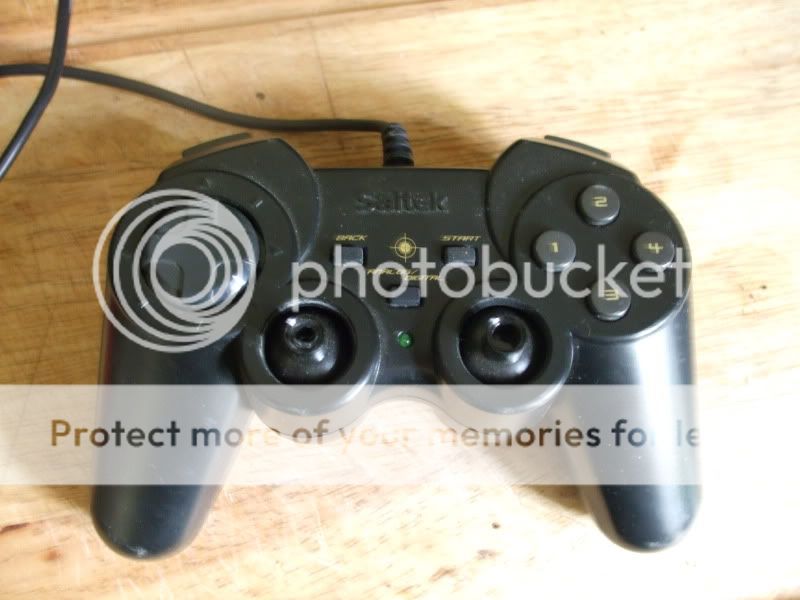
1 x USB controller with a minimum of 8 buttons. (mine cost me 10p)
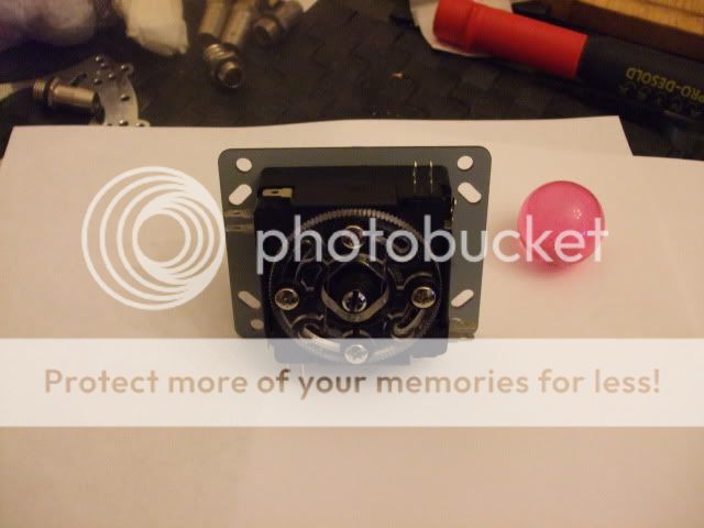
1 x Arcade stick (can be got for as little as £8) Must be 8 way.
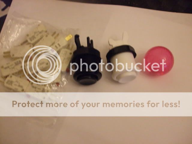
10 x Arcade buttons (they can be got as little 80p each)
1 x Extra button if you want to switch between analogue and digital.
17 x Terminal blocks
1 x Soldering iron & Solder
Some spare MDF or Wood
Wire (cheap ass method would be take a 1 meter RJ45 Patch lead and cut it up
Spade connectors (female) (not needed though)
1 1/8 " Wood Hole drill bit and drill.
Some screws.
a saw.
total build cost no more than £25
Time to rip apart your cheap ass USB controller.
First off i have several Saitek PS2 style controllers that i picked up for 10p because they were to say the least not in a good state so ill be using these for the project. They how do work perfectly fine just there a mess.
So first thing to do is get out you cross head screw driver and remove all the screws and strip these little baby's down because were only after the guts and nothing else.
Now one of the good things about these controllers is that the have the buttons named on the PCB's (this is really handy). Now once its fully stripped down take the casing and throw it in the bin.
See all the plastic buttons that are on top of the PCB take them off and throw them in the bin as well as they are not needed any more.
Now you can see there is 4 parts the the controller there is the left and right shoulder pad buttons and then the buttons for the digital and analogue well get you scissors out and chop away the 2 x shoulder button pcb's and the digital pcb as well but make sure you cut right up to there pc's as were going to need all that wire later on.
Now on some forums people like to leave all this in place but me personally think its just a waste of space and there not needed so get rid of them.
Now you can see there is still the Analogue left and right sticks still left on the pcb's. I have read hundreds of hacks and every one all ways leaves these on but never use them. I know why they do this its because they don't understand how to get around them and when they are removed the controller goes nuts and doesn't work properly in the pc.
So Cut them off lol .. Ill show you how to fix this problem. You can remove them but just wiggling them left and right and they just fall off in you hands ...
Here are a few pics of me ripping them out (yes i did just rip them out). You may need to de solder them but i never do !!!!
Now were still left with the two buttons that when you normally press the Analogue sticks will act as buttons well there not needed so again just rip them out.
Now you can see were just left with a bare board except for the leads. Now turn over the board and you can see there are 2 diodes were the analogue sticks use to go to, these need removing. To do this just cut them away
so you'll have 4 to remove If you don't this hack will not work properly.
Now just to the right hand side of the left set of diodes that you have cut out is 3 solder points. These need grounding to another part of the bored. so what you need to do is grab your soldering iron and Connect all 3 lines up and then solder a single wire to a ground point on the controller. Here i done it straight to the usb.
Now if we didn't solder the points and ground them when you connect the controller up to the pc it would be looking for the analogue ports and looking for a signal. well because we have cut them off it would not receive the signal and would go nuts and just either keep chucking a ****ey fit saying controller not connected or will just not load the driver. So by grounding the points you are telling windows and the controller that the analogue sticks are connected and set in a central position
...Oky now for the next bit get 17 terminal blocks and screw in the Gray wires you have left over at the top as these are your -
Left
right
up
down
Shift key (change between digital and analogue)
Button 1
Button 2
Button 3
Button 4
Button 10 (start)
Button 9 (select)
all so wire in the 4 shoulder buttons and the ground so you have a extra 3 plastic blocks on ether side.
Button 5
button 6
Ground
Button 7
Button 8
Ground.
(i have run out in the pics but ill just solder direct to them)
You now has the basis for a cheap ass Controller for a arcade system.
Now what you can do is plug in the controller board (that's what we will call it from now on) to the pc. Go to the joy stick panel and you'll see you controller has appeared. Using a single wire connect it to any ground (GND or black wire ) and touch each connector that you have screwed into place. each time you touch one of the points it will show up as a action on the joy stick control panel.
so you can see its working.Now put you controller board to the side as we wont need it till later on.
building you Arcade stick controller box
All you need to do is make a box to fit every thing in and a top and bottom. Now this can be made of any thing you like. I have seen some one do it in a shoe box which was quite funny but wasn't really going to take a good pounding. So ill show you a nice little MDF one lol ...
First off it would be a good idear for you to print off The arcade lay out of the buttons and stick.
Here is a link to what you need to print for the Street Fighter 4 lay out ->
These images are from slagcoin.com credit belongs to them not me
http://www.slagcoin.com/joystick/layout/horis36_m.png
Print it out as landscape and DO NOT STRETCH TO FIT
All so you may what to print out the buttons for the start and select and maybe Shift key .
Again do not stretch to fit. if you don't want the shift key just cut it off.
As you can see the layout closely matches the SF 4 £145 arcade stick ...
Now what you need to is cut you your top and bottom out of MDF or wood to size. I do recommend you put you hand on the template and test you Right palm as if you playing so that you can cut the box to your own size hand this helps make it better for you self and game play.
Now once you have the top and bottom part ready place your template on the to the MDF / Wood piece and stick it into place were you feel it best suit your needs.
Once that is ready make sure before you drill the 1 1/8th holes that you have a peace of wood underneath your peace so not to splinter or crack the wood or MDF.
Take your time and dont go to fast.
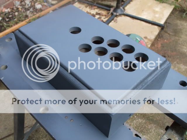
Once finished you can see the shape take place ..
Oky next you need to mark out you start button and select button on the back panel like so and then cut them out.
Then start putting you box together. Now if your a good wood worker you'll do a much better job than me im rubbish ...
Dont forget a small hole for the cable to come out (runs off to do that bit lol)
Now My wood working skills are real bad but never the less here is the main part of the box made....
But my wood filling skills rock Not .....
Oky then you need to sand off all that gunk that you have just used to fill your mistakes
...
Here i just routed a edge to clean it off a bit.
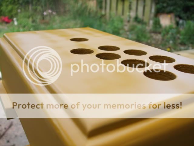
Once that is done and your happy you then need to paint it. Ill be using some spay cans i have left over from another build to do it so no cost is involved.
After a few coats give it another good sanding and you may still need to fill a few gaps. Once that's dried again give it another few coats of primer .. You'll see its starting to take shape.
The inside has been primed and the new layer of Black mat pain has been added. this has 4 layers of paint on after every 2 layers i sanded down with 2000 Grit wet and dry.
Now it needs to be left 24 Hrs before we varnish it.
(first coat of black)
(4th coats)
Curing
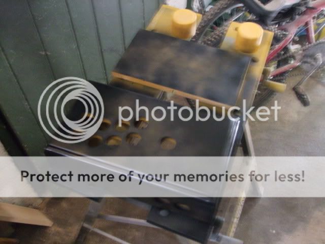
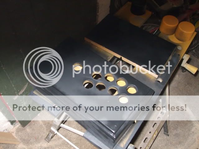
Just a test pic of the button placement ...
These were ordered from gremlin on Thursday and they are happ's with cherry micro switches giving a very fast response time and a nice firm click sound. Very happy with them.
Oky once you have varnished your box you need to let it dry. Then once that is done throw in you buttons and your joy stick and then we need to start putting together the pad pcb that we made earlier on.
Wiring UP time
Now this is How to lay out your wiring and connect up all you buttons a joy sticks.
Im going to show you first the basics of how all this work because it is rely simple to understand and any one can make ther own Arcade stick and it is not difficult.
First off we start with how a switch works.
Here we have a Micro Switch
When Button A is not pressed It Makes a Contact between B and D
when Button A is Pressed It makes a Contact between C and D
So we are going to wire UP Just C and D
Now To make wiring Up easy what we need to do is wire up all the D's in 1 Go to a ground Point on the Controller PCB.
Then we need to wire up all the C to buttons 1,2,3,4,5,6,7 ect
So that when you press a button or move the stick it makes a contact telling to computer what actions you are doing.
Here is a simple to understand diagram of how this all goes together.
So here the ground wire being started on buttons 5,6,7,8 now you dont have to solder you can use Spade connectors instead so that you can disconnect them if your not happy. But im a cheap ass so ill just use solder instead.
Then we go to 4, 3, 2, 1, up, down , left and right .. Ill do the start and select button later on.
Next we have the second wire being soldered to each button in the same order as we just did the ground wire.
Now there all done