Aluminium Pintail Longboard

RadeonHDx

New member
In the last 2/3 months I have fallen completely in love with skating and more specifically, longboarding. The thrill of hitting 25mph on what is essentially a glorified plank of wood is something one has to physically do themselves to fully experience it. In fact, I have convinced 5 or 6 people to buy longboards just from riding on mine for 10 minutes or so.

My ambition was to build my own longboard by hand that I could be proud of and that I could truly call my own with an original design. I began by looking into getting some wood and seeing how I could press it into any shape etc. I had found some wood that I wanted and the design I wanted so I approached my dad with the intention of him helping me with making it. I showed him what I wanted to do and he said he had thought of a good idea, "Well, why don't we make it out of aluminium. No one will have one like that!". I told him that It would be a really good idea but wouldn't be very practical because of weight and how brittle metal is compared to wood.

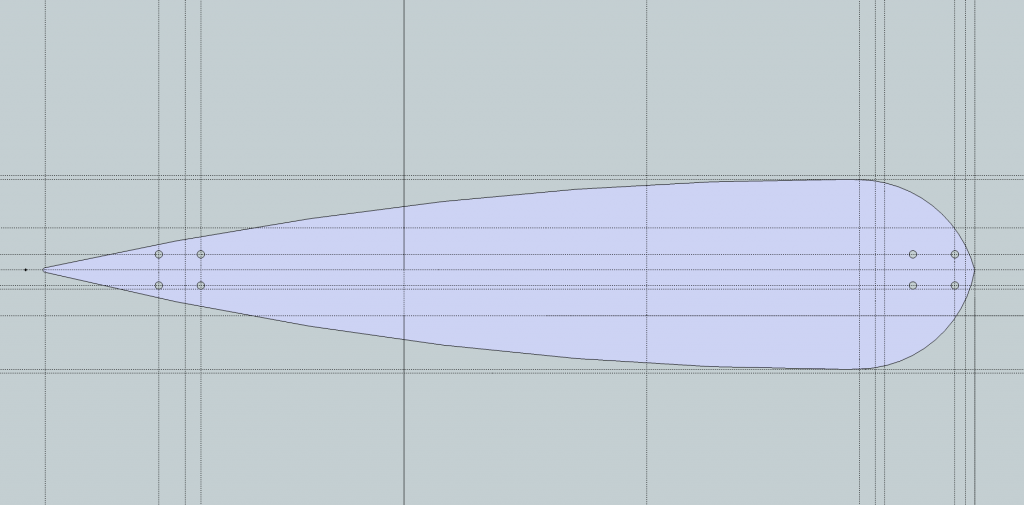
Later, he showed me that he has some aluminium alloy that had flex to it and was a reasonable weight. I began to design and came up, very quickly, with a simple design that I could base my later revisions on.

A 49"x11" monster pintail longboard.


From here I figured ways to keep the strength of a solid longboard but with milled chunks taken out which lead to 4 further revisions of my basic design. Each revision became more aesthetically pleasing and lighter while retaining the key strength that I needed.

Rev.2


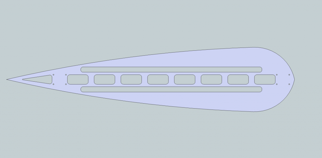
In this revision I had begun to remove sections of material to see how it effected weight and to see if it would be strong enough.

Rev.3


This was a continuation of the design I was trying to use in Rev.2 however my dad later told me that the holes would be on realistic because I would be losing too much strength by having long, unstructured holes.
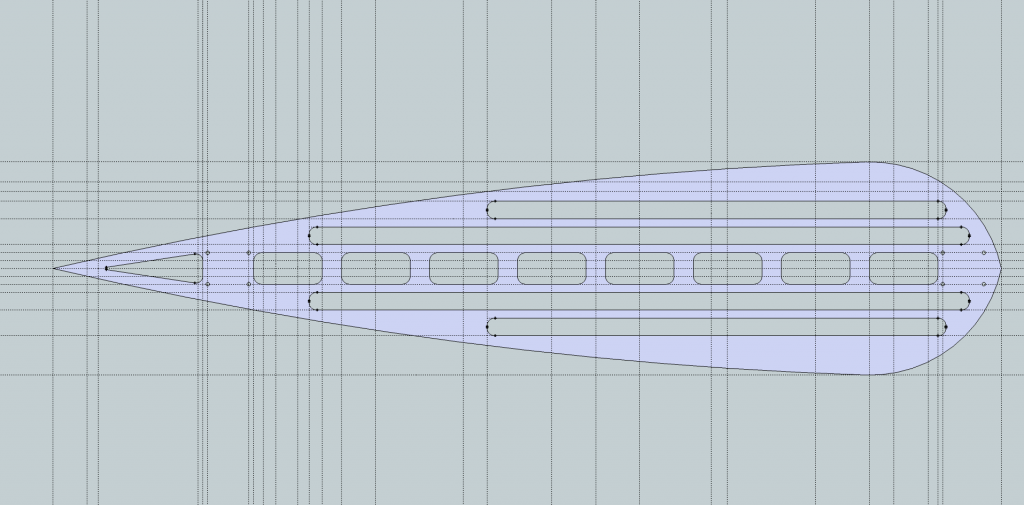
Rev.4


This revision was inspired by a design I saw on the internet. It has not too large holes but dumps lots of material while keeping most strength. This stage was the original final design but I later realised that the largest holes would be over 8cm in diameter!

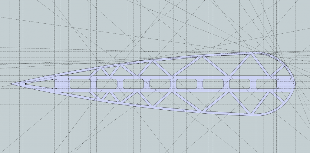
Rev.5 - Final Revision and Potential Design


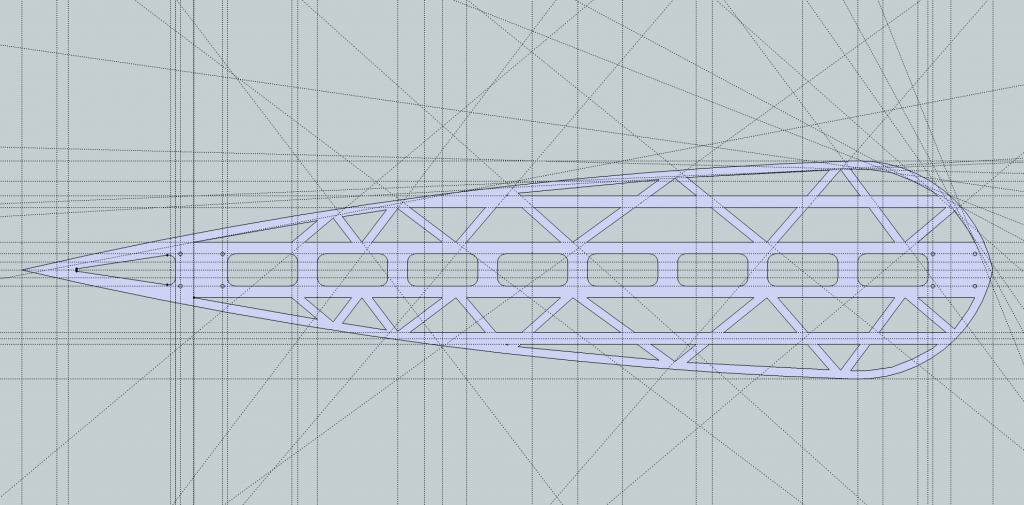
This is a much improved Rev.4 and is more of a Rev.4.2 if anything because the only change that has actually been made is that supports have been added to add strength without adding much mass at all.

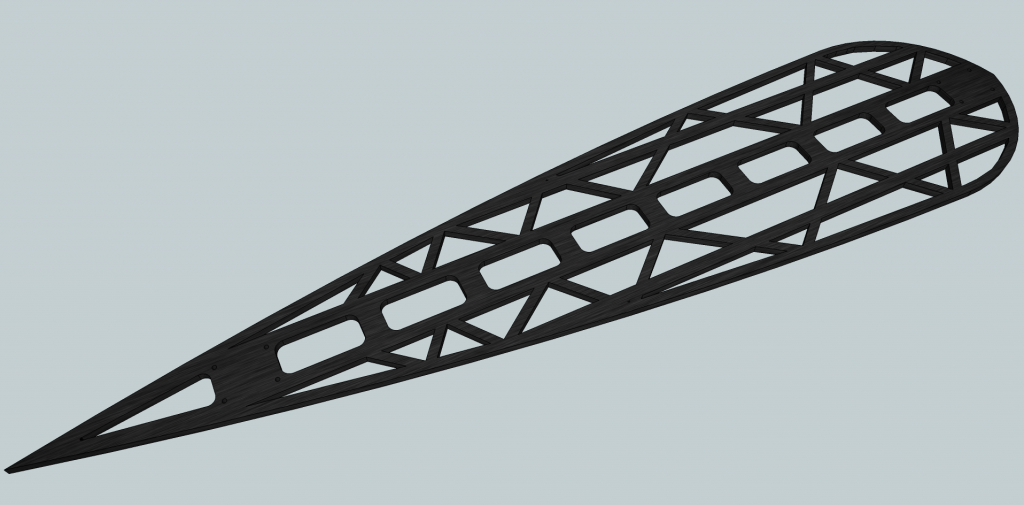
Full render in SketchUp


As I write this I am writing the coordinated that the CNC will have to follow and at them moment with about 1/3 of the coordinates written, I have written a full A4 of coordinates!

On Saturday I will be going down to my dads workshop and dialing in all of the coords and first testing on a piece of wood before hopefully getting it done in ally on Saturday evening.

I will post my updates on here as the project progresses. Any suggestions, comments or criticisms are welcomed (as long as they are justified ^_^)

Thanks for reading :) I hope you enjoy.
Joe
 
I see desks in the build logs sections and they're just as much PC's... This is a section for your projects that you want to share not just for PC's.
 
id put a radius on those triangles ... will keep and resist focal stress points ... doing mechanical engineering as a degree and you could groove the under side, to shave a few grams maybe even upto a kilo
 
Last edited:
id put a radius on those triangles ... will keep and resist focal stress points ... doing mechanical engineering as a degree and you could groove the under side, to shave a few grams maybe even upto a kilo

i doubt that they'll have sharp points on them even if its not specified. CNC's can only do so much with a round cutting tool, unless he has access to something pretty fancy.:o
 
I'm not dead on with the scaling, but won't the trucks be a little close to the edges?
 
id put a radius on those triangles ... will keep and resist focal stress points ... doing mechanical engineering as a degree and you could groove the under side, to shave a few grams maybe even upto a kilo

Thanks for the advice, but as Kleptobot said after you is correct and I'm going to be using a 5mm or so drill bit aswell as programming in some radii, I just felt it would be wasted tim to put it on every triangle on the model.

Also, I have thought about the grooves and I will probably put some around the centre holes if I can get away with it. Unfortunately to give more rigidity to the centre of the deck I am going to have to put quite a chunky plate under neath where the holes are :(.

i doubt that they'll have sharp points on them even if its not specified. CNC's can only do so much with a round cutting tool, unless he has access to something pretty fancy.:o

Nah, nothing really that special, infact I'm having to rethink some of my design points because of this fact (can only cut a 1m area).

I'm not dead on with the scaling, but won't the trucks be a little close to the edges?

This was also a concern of mine as I felt that if I put 12mm risers for the trucks (standard size, they act like a spacer for the truck and the deck) that I would be way too high off the ground for comfortable pushing/breaking but later looked back over my design and realised that the 180mm truck I have ordered should be big enough that on the front truck that there is clearance but only becomes a concern when carving really hard and the wheel size becomes a problem, however on the back truck there shouldn't be any problems as the width at this point is just over 100mm so no clearance issues there.


Last night when my dad came in he looked at my design and asked how long and how wide it was. I replied 49"x11" and he said well my CNC can only do 1mx1m... At this I got quite annoyed that he hadn't told me this before but then realised this opens up new opportunities for deign ideas by connecting multiple panels of the deck on a central block of aluminium with bolts.

This is still quite annoying as I had nearly finished writing out all of the coordinates for the machine to follow on paper and I will now have to red them when I was off by just 66mm... I will post pictures of the shrunken deck shortly along with the pages of coords I need to write out.

Thanks for the interest and help, guys! :)
 
by close i mean the hole is close to the edge of the material, creating a stressor/weak point. ally being quite soft would lend me to thinking it might sheer off ?
 
a round tool on any cnc machine can give a radius, any point is literally a point were stress will be magnified even if you can sand in a radius manually that will help, mechanically.
 
by close I mean the hole is close to the edge of the material, creating a stressor/weak point. ally being quite soft would lend me to thinking it might sheer off ?

I wouldn't have thought that would be that big a concern, although i give it to you because it looks small from the pictures and in fact there is atleast 15mm on material between any hole and the edge, or any other hole for that matter.

Just a small update too in regards to the size issue. I have managed to keep essentially the same shape but I've had to cut the point off the tail which is a bit of a downer for me but it means that I can keep the rest of the deck how it is albeit with a bit of added weight caused in directly by the CNC size restrictions.

First I'll show you what I have come up with for a solution.


As you can see I have had completely separate the nose and the tail and add in that support brace that is at the top of the picture. Inherently this will add weight and introduce its own set of problems, the largest and most obvious is that the bracket itself is actually 1034.6mm long... I've reached the 'I can't win' stage in my project which means that I'm nearing the end of the design :).

Fortunately I have you guys to help me figure out a solution, really I think this is my only real option as shortening it in any other way than cutting the tail shorter would mean a complete redesign as the triangles are relative to the side they are closest to.

Any ideas that you guys have will be really appreciated as really I'm at a loss as to what to do and tomorrow is the only time in the next month when my dad is available to help me with certain things such as the curved edge of the deck.

Again thanks for the help and comments.

Joe
 
for a start if thats a sheet print out, of the cutting plan rotate it by 30 degrees you can get a solid cut out and probs work in that point. and have a tube all the way down fill it with a resin and it will allow a slight flex and create a composite material if it was my build id have a web pattern between 2 thinner sheets, and pressure bolts to hold it together.
But thats me lol
 
The project may be put on hold for a little while while my dad figures out that just because he can't use his own CNC very well doesn't mean that I can't. It seems that he has got it into his head that I won't be able to put the coords into the console properly because he struggles to... He also seems to be forgetting that I will inherently understand technology better than him.

Anyway, rant over now, It seems that I'm going to have to make something literally point to point for now so it looks like its going to be closer to 36" and a more conventional longboard shape. But hopefully, if I get my way, I'll be able to give the pintail design a go tomorrow on atleast a plank of wood and will post updates as they come.
 
Well as a stepping stone and practice using the Hurco, I have designed and programmed a different, much more simple longboard shape. I am calling it the 'Brick' as this is the general name for these kinds of boards.

Today after a few days of the programming being postponed because my dad was using the machine for work, I finally learnt how to use the Hurco and learnt how fiddley it can be just to do something simple as making a curved line. In the end it took me 2 hours of figuring out and typing to finally get the shape I wanted at a reasonable weight. This is what I came up with...


(the dotted lines are the milling paths and the blue lines are the expected shape)

from my design that was based on a personal favourite longboard of mine, the baffle 37"


ndeoribaf37top.jpg


Over the next week I will be making the longer pintail and figuring out the challenges along the way with update logs on here :).

Joe
 
Looks good! Also liking that original Baffle 37" one!
Would still be interested in seeing to one from the OP actually built :D
 
Always nice to see different things being hand-made, even if I know nothing about skating! :)

Thanks! I thought it would be abit different from the conventional wood but give even more possibilities and options for design and weight.

Looks good! Also liking that original Baffle 37" one!
Would still be interested in seeing to one from the OP actually built :D

Thanks man :) and as for the pintail from the OP that's going to be my project for the next 2 weeks because I know exactly what coordinates I need for programming things like the 5m radius curve i need for the edge of the pintail shape and now know that I can confidently write out the programming on a sheet of paper prior to actually going down and having to work out all of the coords down there.

Tonight I will hopefully have a new design for the pintail that incorporates more strength into the body while keeping the same/similar weight and core design.
 
Unfortunately haven't had time to get a render out, but fortunately while I wasn't designing I did get a chance to finally get the Brick finished and cut. The next few shots are just quick pictures I took with my iPhone 5.

Fully cut, still in the machine...


The raw deck straight off the machine. Extremely happy with how it turned out :).


Just before going on my first ride :)


and a video of my first real ride, I quickly realized that I would need to put on the risers when I was getting wheel bite with the slightest turn when I went out on it before. Audio f'ed up and I cba doing anything about it tonight.


Thanks for following the thread and the pintail will be coming soon and most likely will be done before the end of the month as I feel I am on a deadline with a big skating event near me (Skate of Independence in Ilkley, West Yorks. on the 4th of July) coming up soon and I want to have it done so I have something to show people.

As always, thanks for following me in my project :)

Joe
 
Last edited:
Nice progress on the board but your brave riding like that on Sheffield potholes, I hated riding in Sheff to many 'oles in't road.. :lol: Good luck up Ilkley and don't forget you can't go to Ilkla Baht 'at. :)
 
Back
Top