mayhem
New member
Repairing a blown Capacitor
One of the most common thing’s to blow in modern day electronics is The rotten old capacitor so really to save a lot of money in these modern days is the ability to problem solve and fix this little buggers. From flat screen tft’s to graphics cards and so on, it really will save you a fortune in long run by replacing the parts yourself.
First off signs and symptoms that show a blown capacitor. Let’s take a good example here from below.
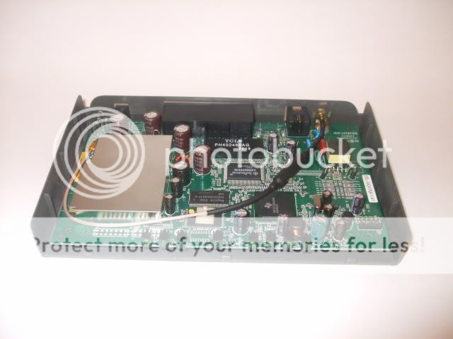
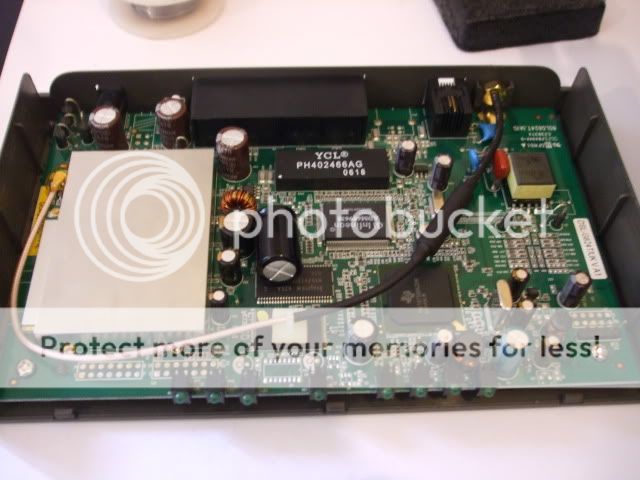
I was called out to fix a router that was only moving files at .2mbs across a network and any internet activity was less than having a 45kbs modem. After getting there I found the router and promptly placed my hand on it to feel hot it was. The heat was well over the top and the first words to come out of my mouth were “Yup a blown Cap”. Taking my trusty little multi screw driver from my pocket I opened the router up and hello my little friend there she blows a nice little raised cap sowing signe’s of over indulgence.
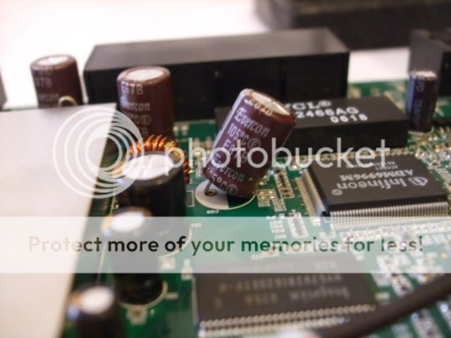
You can easily tell these in several ways if a cap has blown because the capacitor will have either have split or risen to a bulge. Normally caps should be flat and there cross that is the top should not show any signs of splitting.
Blow is the picture of the router and the blow cap.

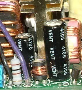
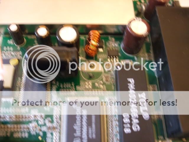
Now the first thing to do is find the details on the cap to replace e.g this one is clearly marked on the side 25v 1000UF @ 105c. So after a little hunting I managed to get 5 for £1.28 + 50p post and packing. Since routers are normally New £50 to £100 or second hand £25 to £50 this is a viable cheap option to repair.
Pic below of the details of the cap.

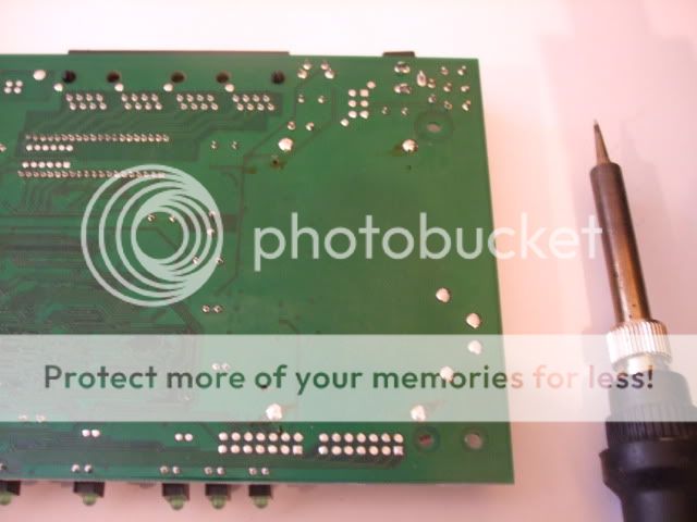
Here is a pic of the pcb underneath.

Now using the soldering iron were going to heat up the points and remove the old cap out.
Here you can some very doggy pic’s of me disordering the leg at the time pulling on the cap at the same time taking a photo lol. (so if i can do that any one do this whole thing)


Once you done side then move onto the other and gently remove the cap.


Now that’s done here you can see the new cap .... Ops ... i messed up and order larger caps than i needed but i don’t care its still going in ... Just a little extra modding is required to the case but hay that’s life. Normally you should try and place the cap with the same one but since this is the same rating ect ect it will work perfectly.

Here you can see it now soldered in. Because of its size i have had to do it lay it flat but I don’t care lol...
So once finished a quick test. As you can see its seems to be fully working so time to fire it up on the network and see how it goes.
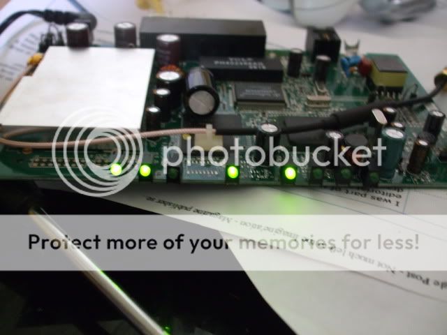

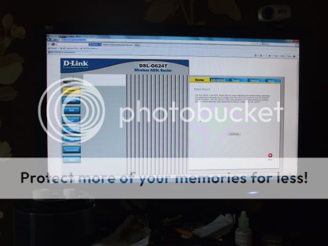
Perfect all working running at full speed.
The time to put it back together.

Because the user decided they couldn’t wait 3 days they went and bought a new router and don’t what this one so i’ve ended up with a router i don’t need asp since im on cable lol ....
One of the most common thing’s to blow in modern day electronics is The rotten old capacitor so really to save a lot of money in these modern days is the ability to problem solve and fix this little buggers. From flat screen tft’s to graphics cards and so on, it really will save you a fortune in long run by replacing the parts yourself.
First off signs and symptoms that show a blown capacitor. Let’s take a good example here from below.
I was called out to fix a router that was only moving files at .2mbs across a network and any internet activity was less than having a 45kbs modem. After getting there I found the router and promptly placed my hand on it to feel hot it was. The heat was well over the top and the first words to come out of my mouth were “Yup a blown Cap”. Taking my trusty little multi screw driver from my pocket I opened the router up and hello my little friend there she blows a nice little raised cap sowing signe’s of over indulgence.
You can easily tell these in several ways if a cap has blown because the capacitor will have either have split or risen to a bulge. Normally caps should be flat and there cross that is the top should not show any signs of splitting.
Blow is the picture of the router and the blow cap.
Now the first thing to do is find the details on the cap to replace e.g this one is clearly marked on the side 25v 1000UF @ 105c. So after a little hunting I managed to get 5 for £1.28 + 50p post and packing. Since routers are normally New £50 to £100 or second hand £25 to £50 this is a viable cheap option to repair.
Pic below of the details of the cap.
Here is a pic of the pcb underneath.
Now using the soldering iron were going to heat up the points and remove the old cap out.
Here you can some very doggy pic’s of me disordering the leg at the time pulling on the cap at the same time taking a photo lol. (so if i can do that any one do this whole thing)
Once you done side then move onto the other and gently remove the cap.
Now that’s done here you can see the new cap .... Ops ... i messed up and order larger caps than i needed but i don’t care its still going in ... Just a little extra modding is required to the case but hay that’s life. Normally you should try and place the cap with the same one but since this is the same rating ect ect it will work perfectly.
Here you can see it now soldered in. Because of its size i have had to do it lay it flat but I don’t care lol...
So once finished a quick test. As you can see its seems to be fully working so time to fire it up on the network and see how it goes.
Perfect all working running at full speed.
The time to put it back together.
Because the user decided they couldn’t wait 3 days they went and bought a new router and don’t what this one so i’ve ended up with a router i don’t need asp since im on cable lol ....

")
")