Build log of the Proper Copper Pipe PC
(Great name, I know)
Copper has all but disappeared from the PC. It's time for the return.
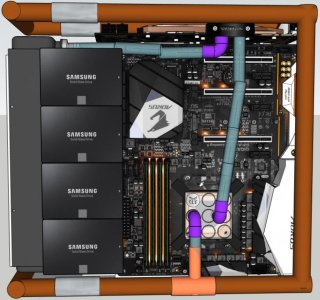
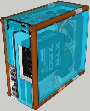
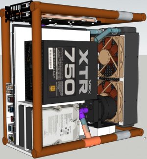
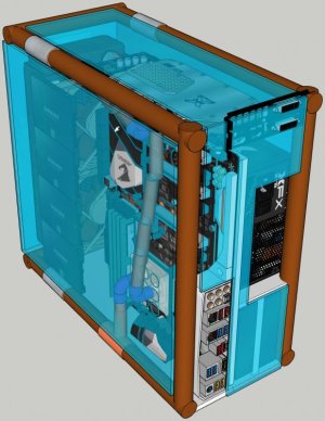
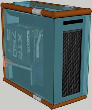
So far there is only the idea and the (rushed) Sketch-Up. You will need a little imagination to understand my awful Stetch-Up model!
More updates to follow.
Introduction
8 meters of 22mm copper pipe.
A crap tonne of short "cut offs" of 15mm copper pipe.
A full set of water cooling parts.
And access to the correct plumber's tools.
Design Requirements
Full ATX mobo and psu.
Easy(ish) maintenance of both the water and the PC hardware.
Space efficient.
Looking incredible.
The design
The Copper
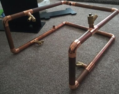
The 22mm copper will be the frame of the case, it will hold water and will be part of the cooling loop.
The corners will be end feed copper 90 degree bends. These will be soldered into place, torch, flux, the lot!
I wanted the outer copper frame to be one continuous loop, so taking inspiration from a tennis ball, I came up with this shape. I call it the U Cubed design, as from any plane it is a "U".
The case "panels" [In the sketch - bright blue panels] will be some sort of transparent plastic, attached to the copper frame with p clamps. these clamps allow most of the width of the 22mm copper pipe to be used by the internal components, as seen by the PSU, SSDs, and the radiator.
I may heat and bend the plastic to create the panels, or may just cut and mount.
There will be two fill ports, and two drain ports. [On the sketch - Grey tubes at top and bottom of the outer copper] These will be 22mm drain cocks, normally found connected to household radiators for bleeding. having the 4 should allow for easy filling and bleeding, I hope.
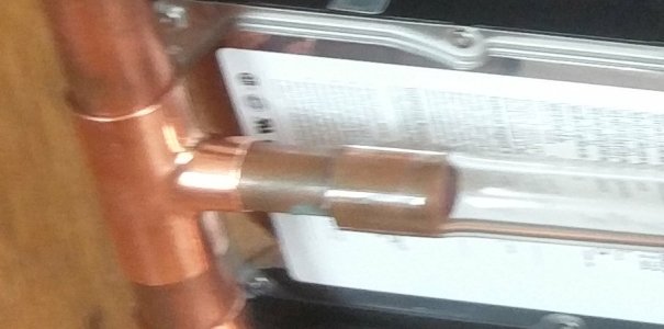
To connect the 22mm copper to the internals there is two 15mm reducing tees. One leading to the pump, and one returning after the CPU block.
A short 15mm OD connecting pipe can, with some encouragement, slide into 13mm ID soft tubing. This connection easily adapts the copper to the G1/4 inch thread requirement of the PC water cooling components.
Once the copper is in its final shape, it will all be soldered together. Polished and lacquered. I am assured this will give a mirror finish to the copper. High hopes.
PC Component Layout
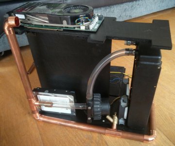
The water-cooled GPU wanted to be on show, right at the top! (The PCI braket will be removed)
Therefore to allow for a reasonable PCIE riser ribbon cable, I was forced to flip the motherboard.
the motherboard tray will likely be steel or aluminium, whatever I can get my hands on.
The motherboard chamber will be as shallow as possible, depending on the height of the 90 degree G1/4 compression fittings. [In the sketch - Bright purple 90 degree connections)
Taking inspiration from the metal cable shroud from the NZXT S340, the SSDs will be stuck to the radiator, and will hopefully hide the power cables etc. Some low profile SATA cables will be needed.
The rear, or left, chamber will hold the PSU, HDDs and the pump.
By "overhanging" the pump and the PSU into the width of the 22mm copper, this chamber should also be fairly shallow.
Overall I am aiming for the total width of the case to comfortable house the 240mm radiator without large gaps.
The Water Loop
The 22mm copper will act as the reservoir but will also transport the water from the CPU block to the Pump.
In the sketch - the copper coloured pipes are all copper. The blue pipes are transparent soft tubing.
The loop order:
Pump -> rad -> GPU -> CPU -> 22mm copper -> pump.
This setup will hold a lot of water, and hopefully the rad plus the copper pipes will have enough cooling capacity to handle a decent CPU and GPU.
Cooling
There will be only 3 fans.
Two intake, one PSU for exhaust. This may not be optimum, but I'm hoping a pair of high pressure fans will suffice.
Air will escape through the PSU, past the motherboards IO and through the gap between the side panels and the 22mm copper.
Now if you've got this far, feel free to share any experience with copper and PC water-cooling etc.
I am hoping to build the case in preparation for a new build later this year, probably 6 core Ryzen, but we shall see.
Thanks for having a look!
If I figure out how to share the Sketch Up file I will do.
Cheers.
Last edited:


