This topic is where I hope to post the build log for a project I have been planning for ages. It carries over from an earlier post where I was getting some ideas. http://forum.overclo...168#entry470168
So basically I wanted to make my Rig into something a bit more unique and give myself a bit of project to get into, hopefully finishing around the release of IB.
The inspiration came from the LEP desk and my visit to LIT, where I saw the Scan Swordfish.
Here is a hastily made model of the kind of thing i'm going for.
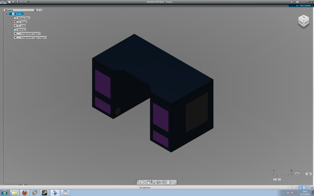
The two tower/leg parts are going to be where I house all the components and at the moment I think the fronts will be windowed and I will leave the top solid. The desk is going to be water cooled partly because getting decent airflow would be a nightmare but mostly because I want it to be quiet and pretty
 Currently im thinking of having the computer components in the left tower and the rad,res and pumps in the right but I might try and get it all in one to make things simpler. There should be plenty of storage space in one or both of them for my computer stuff so that will please the misses, she is yet to see the genius of this for some reason.
Its possible that I will also build my monitor in so that it rises from the desk in a swordfish like manner but I will have to see how im doing for money at that stage as im on a tight budget and have not been sponsored.
Its going to mostly be made of steel box section and sheet as im bored with working with wood and it should make for a pretty unique look.
This combined with a reference to my username is where the project name came from, geek points to anyone who gets it!
Top will probably be MDF.
Components:
CPU: IB (will choose specific model after I see some benches)
Mobo: Will have to wait and see.
GPUs: At the moment im thinking 7970 but will see what the state of play is when I get to that stage both in terms of cash and other releases.
HDD: Already have a 1TB seagate drive
SSD: Probably something along the lines of a Corsair force GT, will see how pricing is closer to the IB release date.
Soundcard: Already have Asus Xonar STX
Monitor: Already have HP ZR24w (ZR30w or U3011 will probably remain dreams )
PSU: probably 1000W Enermax Platimax
Watercooling parts:
Pump: D5 Vario with bitspower top
CPU block: XSPC Raystorm.
GPU blocks: cant say yet
Res: Custom acrylic res
Tubing: Thinking of trying to do some rigid tubing for something a little different, perspex perhaps.
Fittings: Going to have to see how my perspex idea pans out.
Rad: MO-RA3 pro 9x140 (I want this to be quiet as poss)
fans: Noiseblocker PK2s probably. Mabey a couple of scythe GTs to give a little airflow around the components.
Colour scheme is black, silver, hint of yellow perhaps. Iron warriors colours essentially.
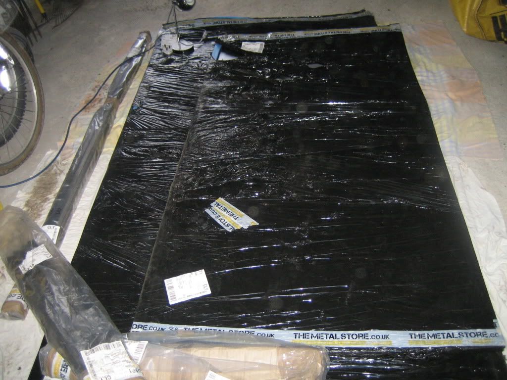
Steel delivered
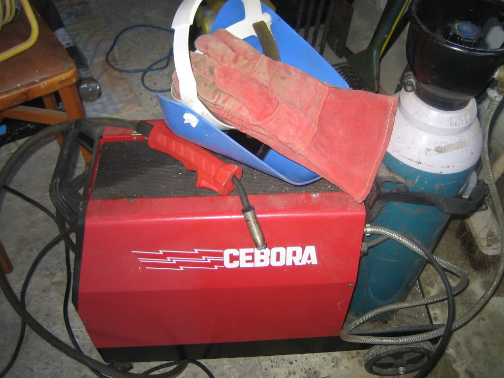
A borrowed Cebora 155 MIG welder. This is the first time ive ever tried welding so it will be an interesting learning experience, possibly a frustrating one but interesting none the less.
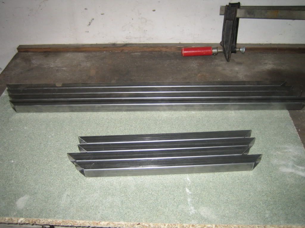
Ive cut the box for the first of the towers, its all 45s for strength. All cut with a hack saw by hand, very tedious.
My first attempt at welding, seems to have come out alright. The bottom section went together fine, only tacked the uprights so I can get them somewhere near square. It would seem the welder is too powerful for me to create continuous beads of weld even on the lowest setting so im just taking one next to the other.
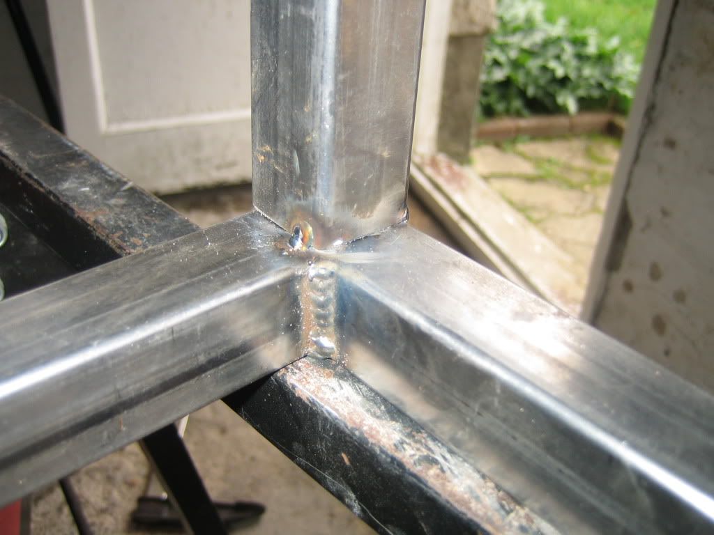
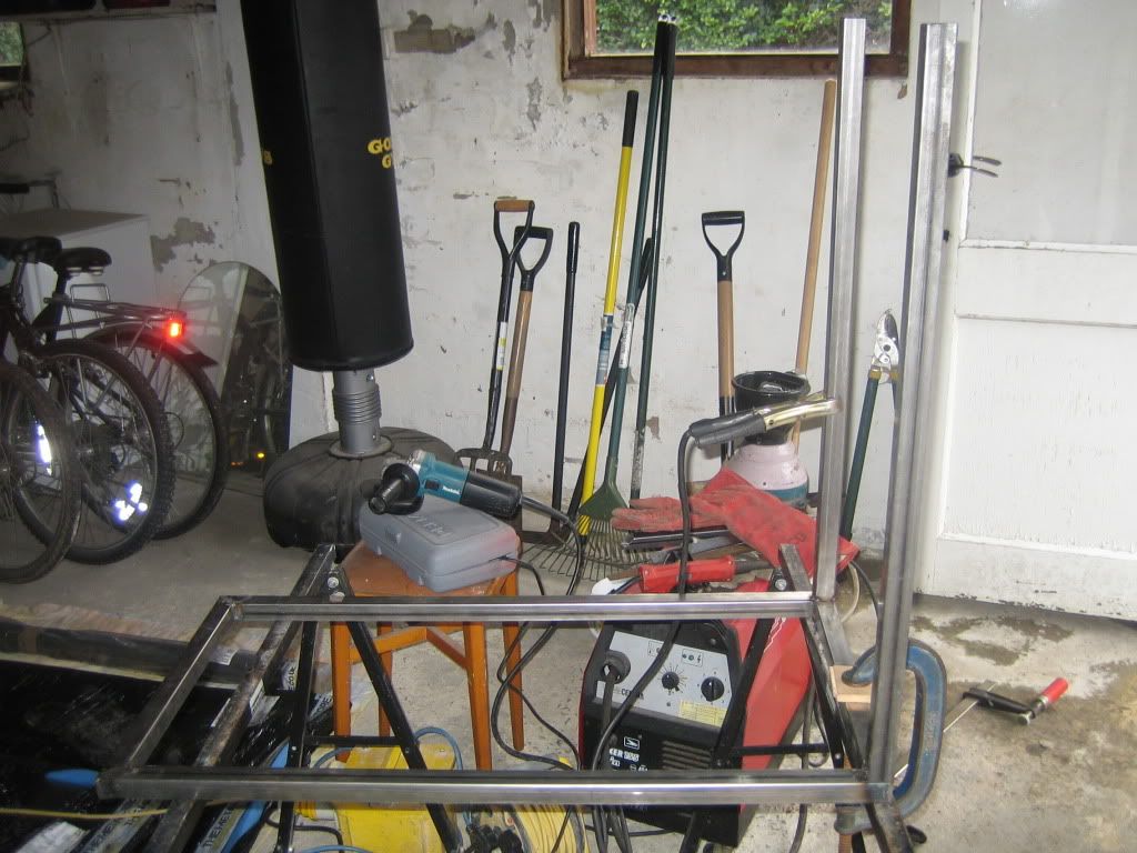
After a solid weekend of working this is what I have to show for myself.
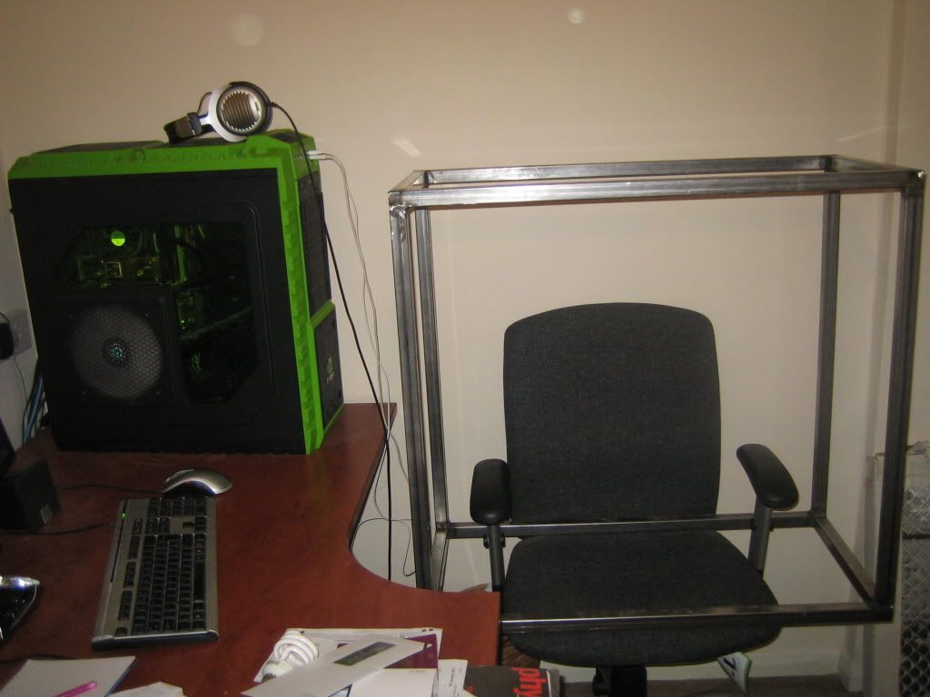
Ive put it next to my HAF-X to give you an idea of the amount of space I will have to work with in each of these towers. The welds have been grinded down on the sides so that I can get the sheet metal on nice and flush. It seems to be strong, it can take my weight so it looks like my welds are good enough.
I will be continuing each weekend so hopefully this topic should get updated at least weekly.
Please let me know what you guys think, advice/criticism is welcome so don't hold back

UPDATE: 29/01/2012
The first tower part seemed to go quite well so this time I have been a bit more thorough in my documentation of the process now that I know it works.
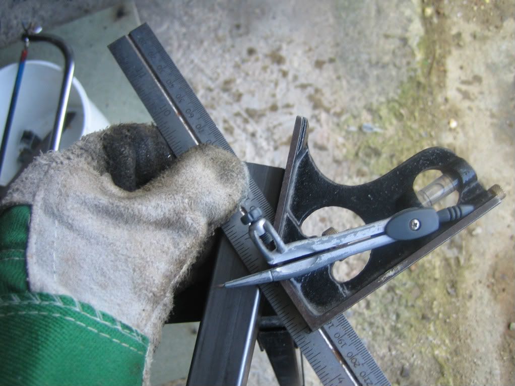
Step 1 was to mark the 45s on the box section I had roughly cut to size. The compass finds its first use since secondary school as a scribe.
Next a bit of cutting with the hacksaw, tried a few other tools but doing it by hand gave the most precise cut even if it did take forever.
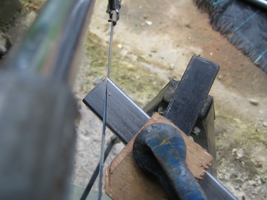
I cut the opposite sides separately so that I knew I was getting a good 45 all the way through.
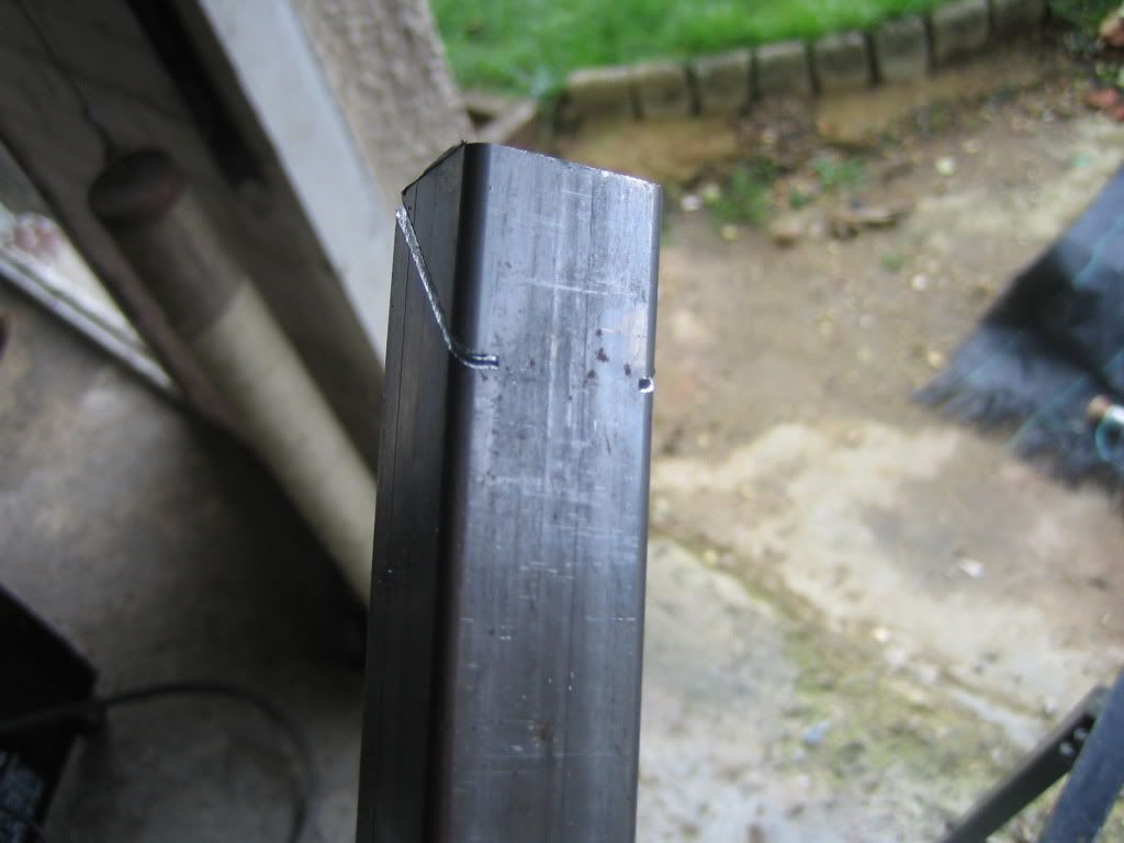
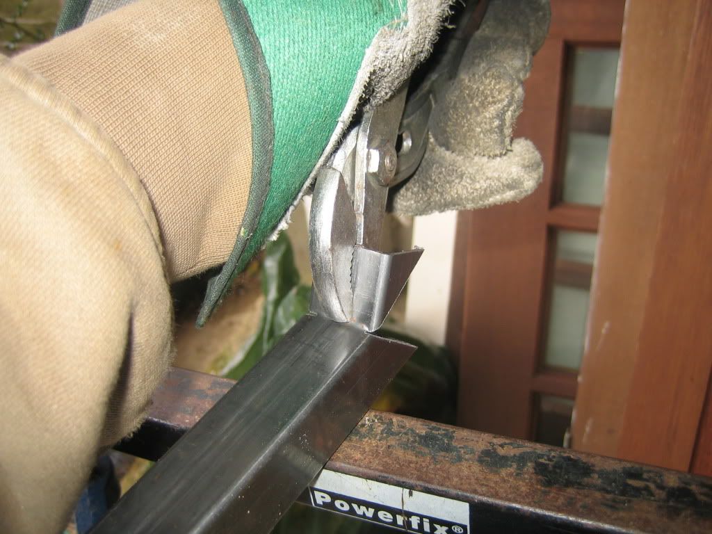
Cutting along the final side without meandering around proved to be a bit awkward so I just cut in a little on either side and used pliers to bend the off-cut until it snapped off.
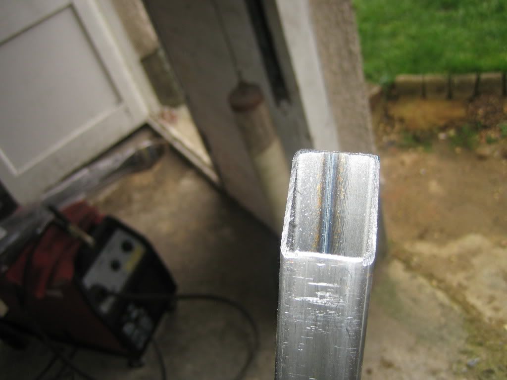
A little filing later and this is the final product. After getting my new best m8 Mr set square to check the angles I repeated this another seven times...
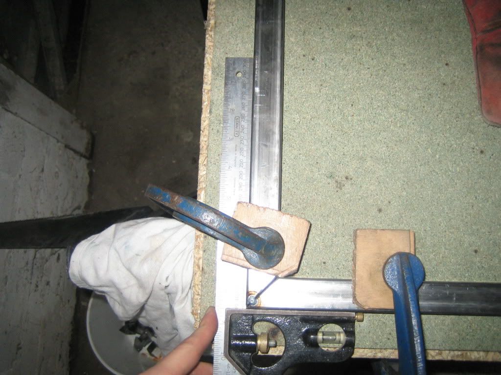
Squaring up a couple of lengths and clamping them in place. I found that the welder exerts a surprising amount of force and will move two parts apart slightly if they are not clamped.
No pics of the actual welding process because I didn't have enough hands and the misses wouldn't come and hold the camera because she doesn't trust me not to weld her somehow. So after all the welding we get to the assembled tower. Only had time to tack the uprights in as it was getting too dark to see but I can finish the welds and grinding off one evening.
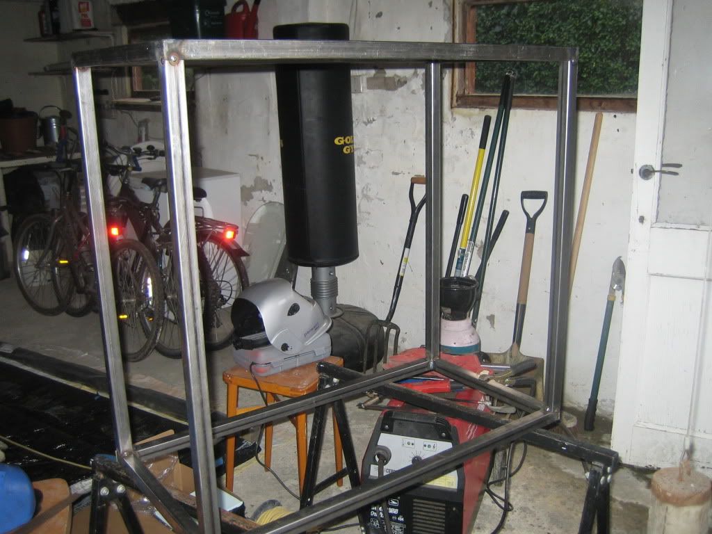
Not too exciting an update but the structure is essentially done. After this I can start making the skin, mobo tray etc so things should start to take shape. Might even order the PSU and start the paracord sleeving.
UPDATE: 30/01/2012
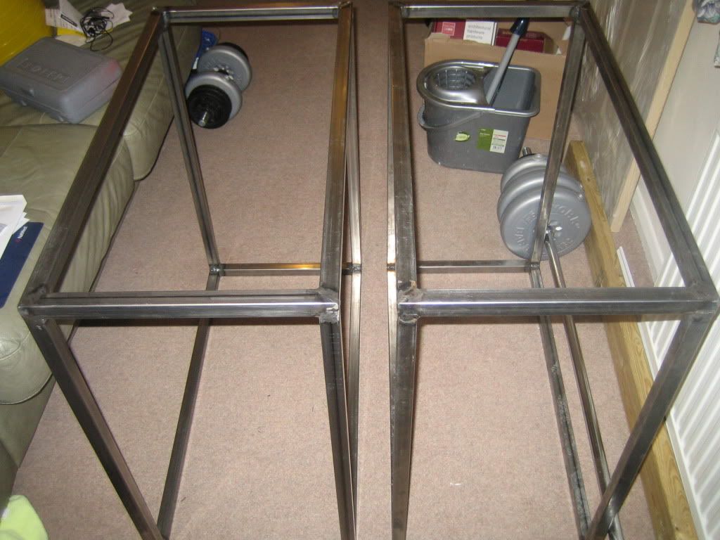
Just a quick one, finished off the welding and grinding this evening so now I have two giant towers

UPDATE: 13/02/2012
First update in a while, cutting the sheet steel was a bit of a nightmare with my little grinder so this weekend I got my dad to come over and bring his jigsaw. Bought some lovely Starrett fine toothed metal blades, which promptly cut the steel like it was paper

So first we got this 2.5x1.25 m sheet onto my improvised bench, which I was glad for some help with, it is heavy, bendy, unreasonably large and unwieldy all at the same time...
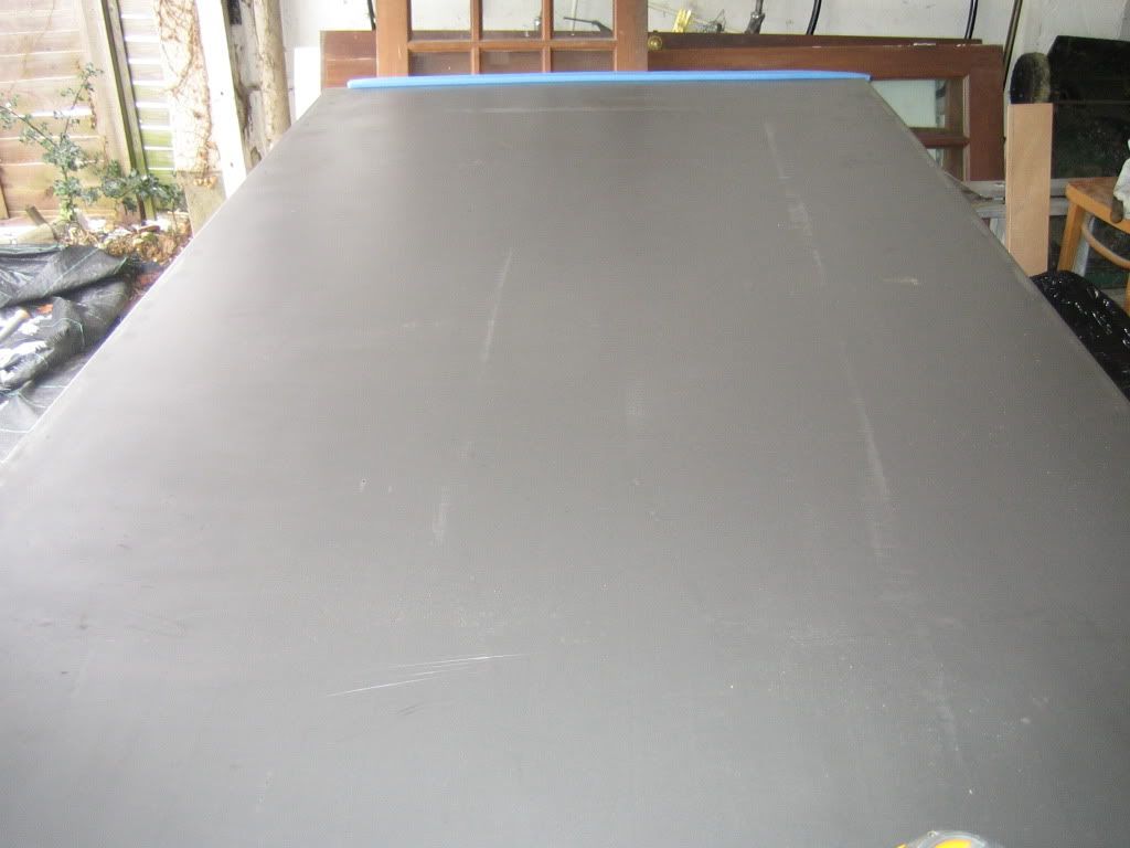
Sometimes the things you assume will be straight forward turn out to be the most difficult, this was the case with marking a straight line. My scribe ( ok its a compass but shh..) made a nice thin line to follow so the cut was precise, except it was difficult to see. So we tried going over it with a pencil but that made a thick line and drifted under the level we were using as a straight edge... After rubbing the pencil out we found it had stained the scribed line, solving both problems, inadvertent success is the best kind

My dad models the Festool jigsaw and 80s Ski jacket combo, very big this season.
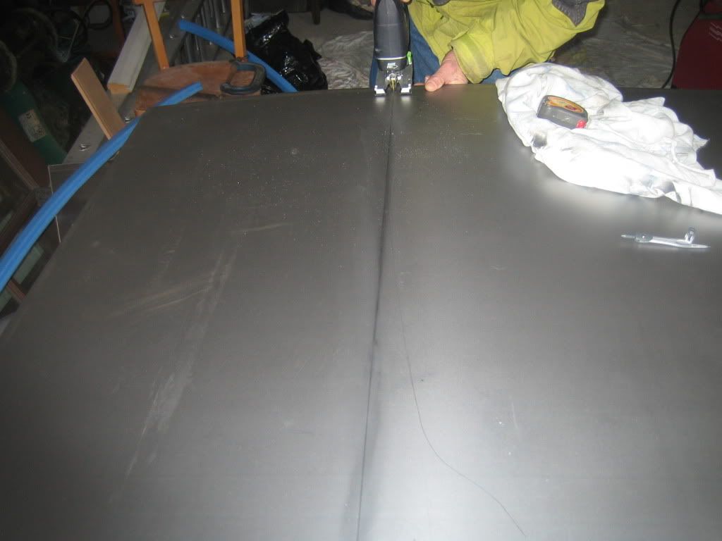
So after some rather easy cutting steps we have a sheet of 2x1 m, the right size to form to one of the towers. The steel has got a bit scratched up living in the garage but they are mostly not deep at all and I think I can polish most of them out.
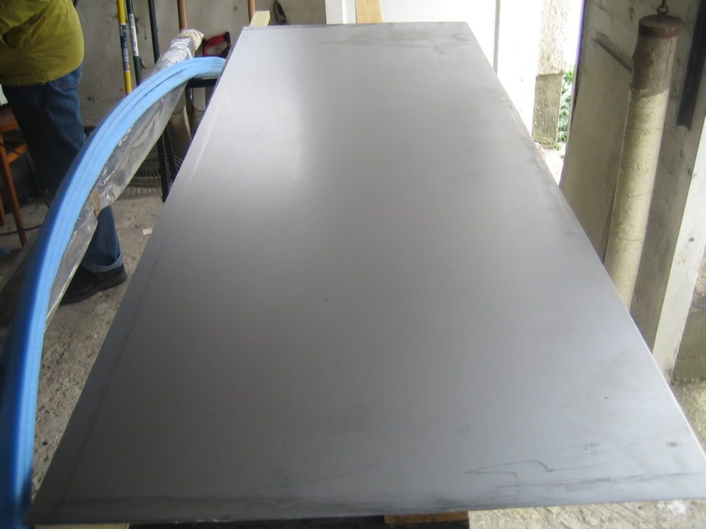
And then there were two! They get to move inside now so as to reduce rusting.
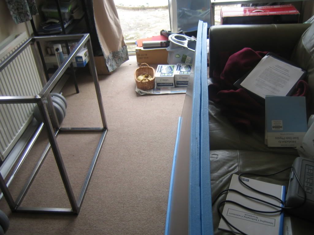
I also received a delivery from Specialtech
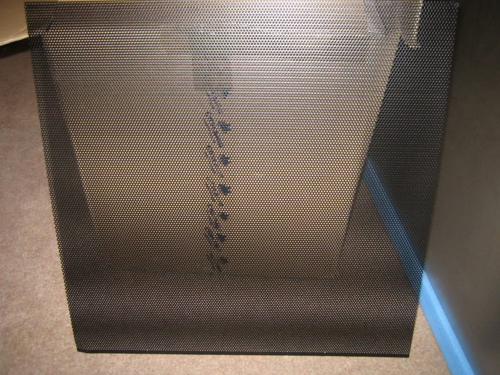
 A 500x500 mm piece of mesh to cover the intake to....
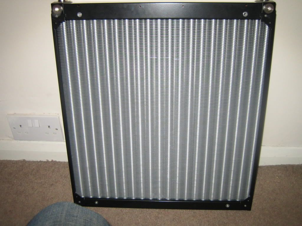
My new MO-RA 3 9x140 LT, I don't know whether this is a beauty or a beast...or a beautiful beast if there is such a thing?
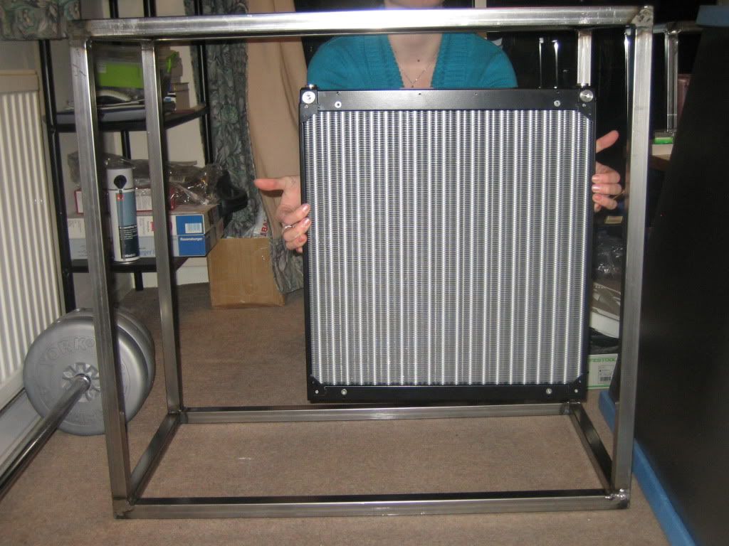
After minor cajoling I managed to get a lovely young model to hold the MO-RA vaguely in place within the right side tower, whilst desperately trying to stay out of shot.
That's all I managed over the weekend but now that this hold up is out of the way I can get on with the next few bits. Building a rad mount wont be too difficult so that will be done soon. Forming the sheet around the towers will be a challenge and I shall have to think long and hard before I give it a go as I only really have one shot.
UPDATE: 19/02/2012
Right this update was huge in terms of the time it took me but probably doesn't look like much from the photos!
With the Rad here I decided to make the mount for it. So first I cut up the box section with my now blunt hacksaw.
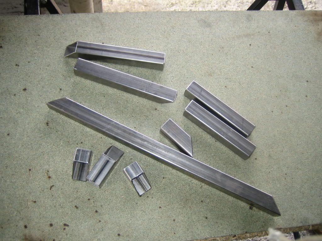
Next I welded together the parts to make the mount easier to assemble. The rad will be screwed to a piece of sheet metal that will bolt to the top piece show in the pic so that I can remove the rad more easily should I need to. The lower parts are legs, yes I know two are shorter...have faith

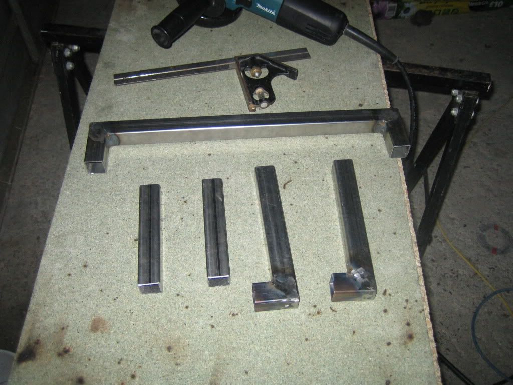
Back legs are welded in place, the L shaped part gives them more contact area with the ground.
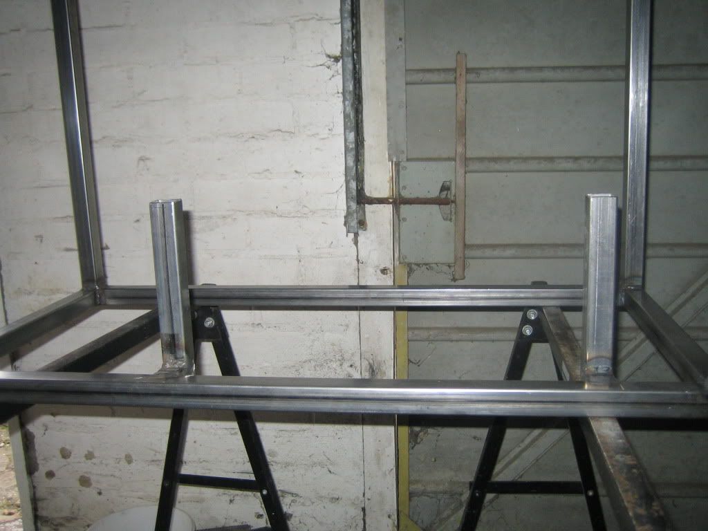
We have jumped forward in time a bit here but I forgot to take a picture at the time
 Both legs are in place, the short ones sit on the outer frame. It got dark before I hard time to weld the top on, but that wont take long.
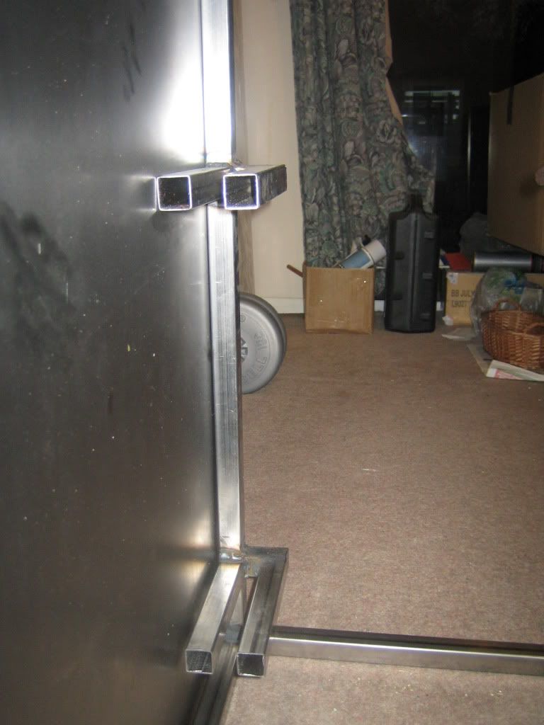
Now to making the "skin" I put one of the frames on top of the sheet steel, marked the bends and scored them.
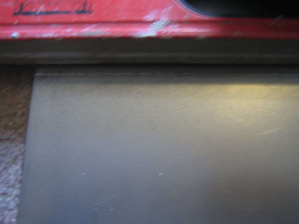
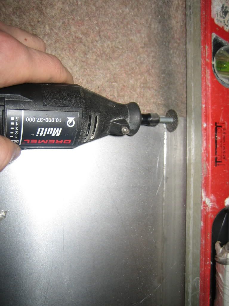
I have discovered 1mm steel is stronger than I thought...bending it without a break is almost impossible so I decided to make a fault in it to force it to bend when I apply a silly amount of force. I used the dremmel to cut ~1/3 of the way through the steel.
I got a little too into the cutting and didn't notice the huge amount of fine black powder I had got allover the floor....Fearing for my life I looked for something to clean it up without making it worse and found my magnet pen, it actually pulled it all out of the carpet! So assuming the misses doesn't become an OC3D member all evidence is disposed of

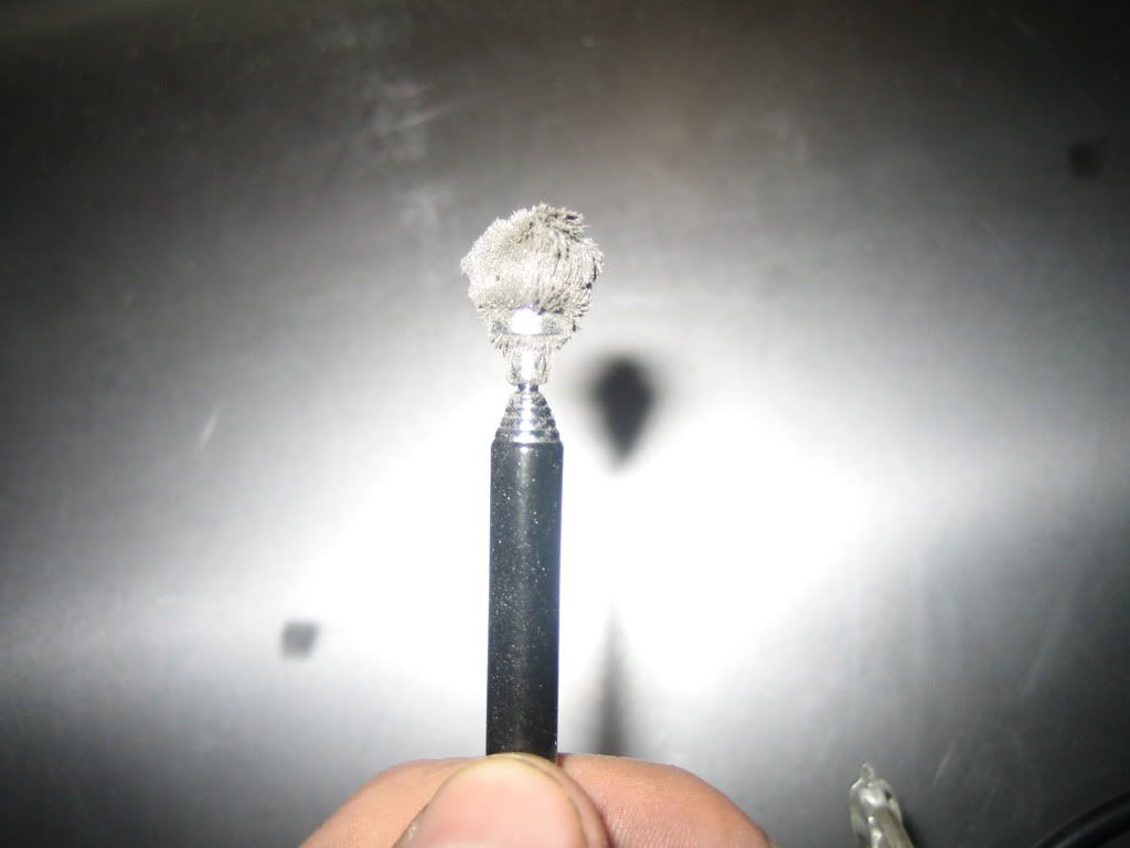
I think I got my moneys worth from this disc, time for a new one I think.
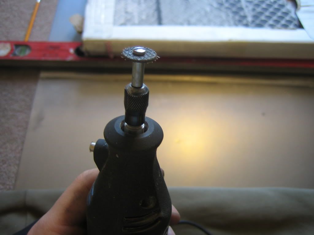
Cuts made for both bends, next how to bend something this unwieldy with none of the right tools!
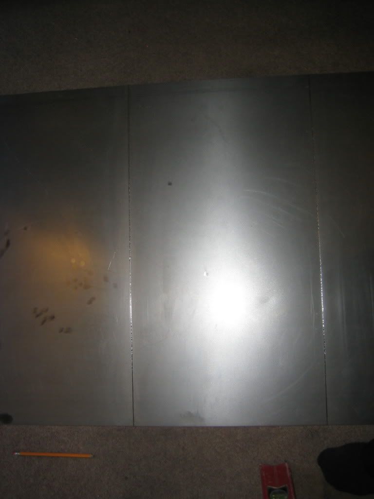
I put some chipboard under the steel and one of the towers on top, in line with the cuts. Next I applied weight, 3 slate tiles and one small person was sufficient.
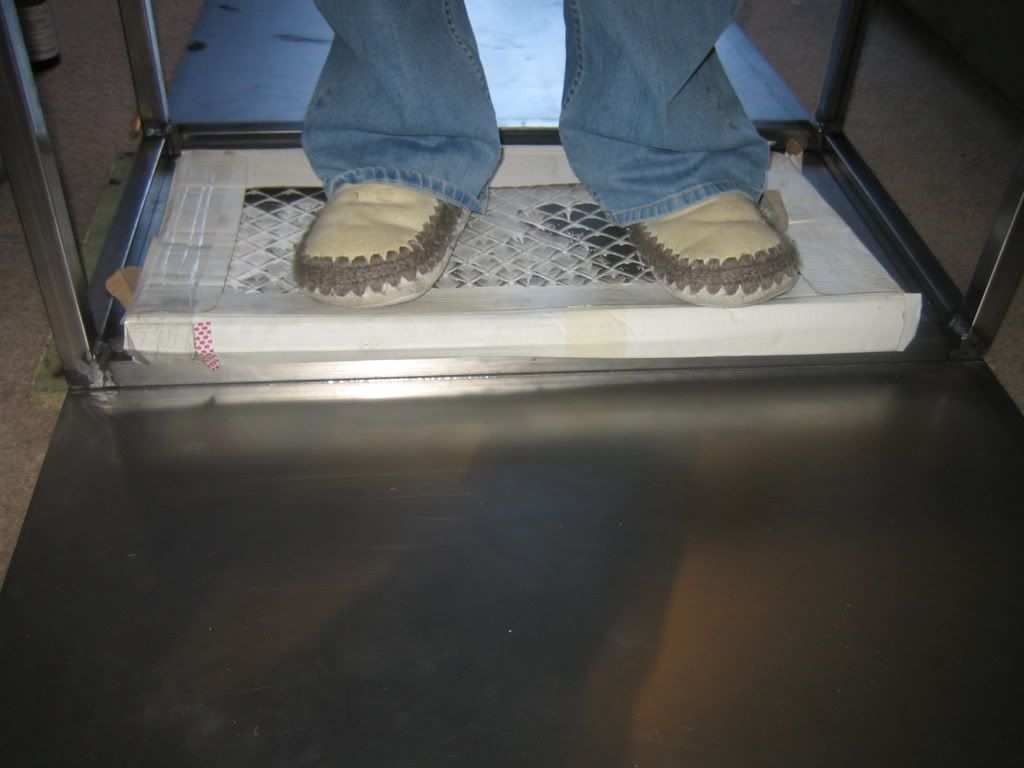
I got another piece of wood and put it under the side pushed right up to the chipboard. Then I pivoted it against the front corner, which took a surprising amount of force. This only got me to a ~ 45 degree bend.
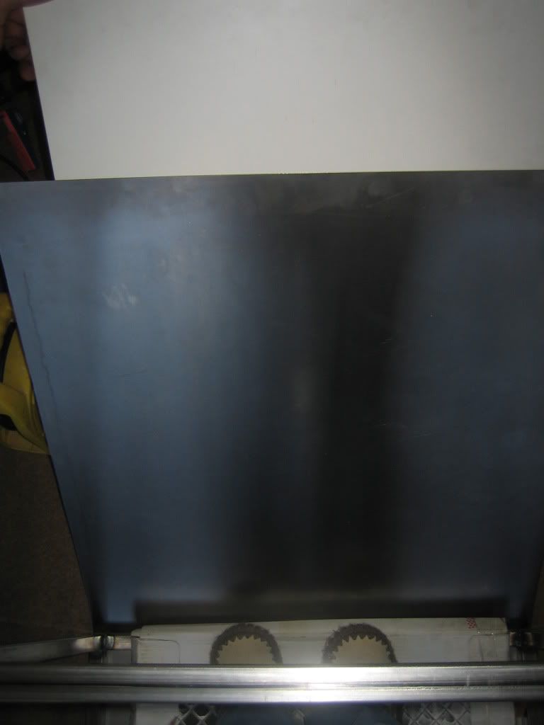
This was the third way id tried to bend this and had been at it all day so i lost it a bit and decided to...

Enough clamps? seems to have tamed the unruly steel nicely.
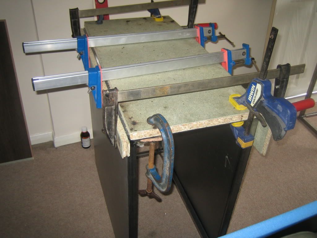
Alright if you insist, one more...
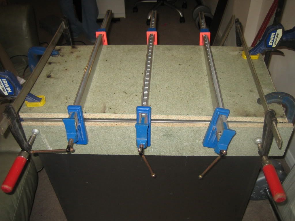
Here's the finished product, pretty happy with the bends. Its not quite there but when I decide how I fix it I can probably deal with that.
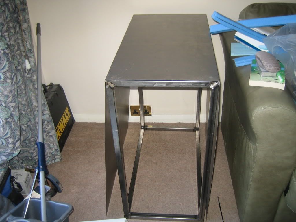
Got plenty done this weekend, that bending was so time consuming so im glad its done, the project should go pretty smoothly now thats done I think..... I hope.
Next is finish rad mount, work out how to fix the sides and cut out the windows.
UPDATE: 20/02/2012
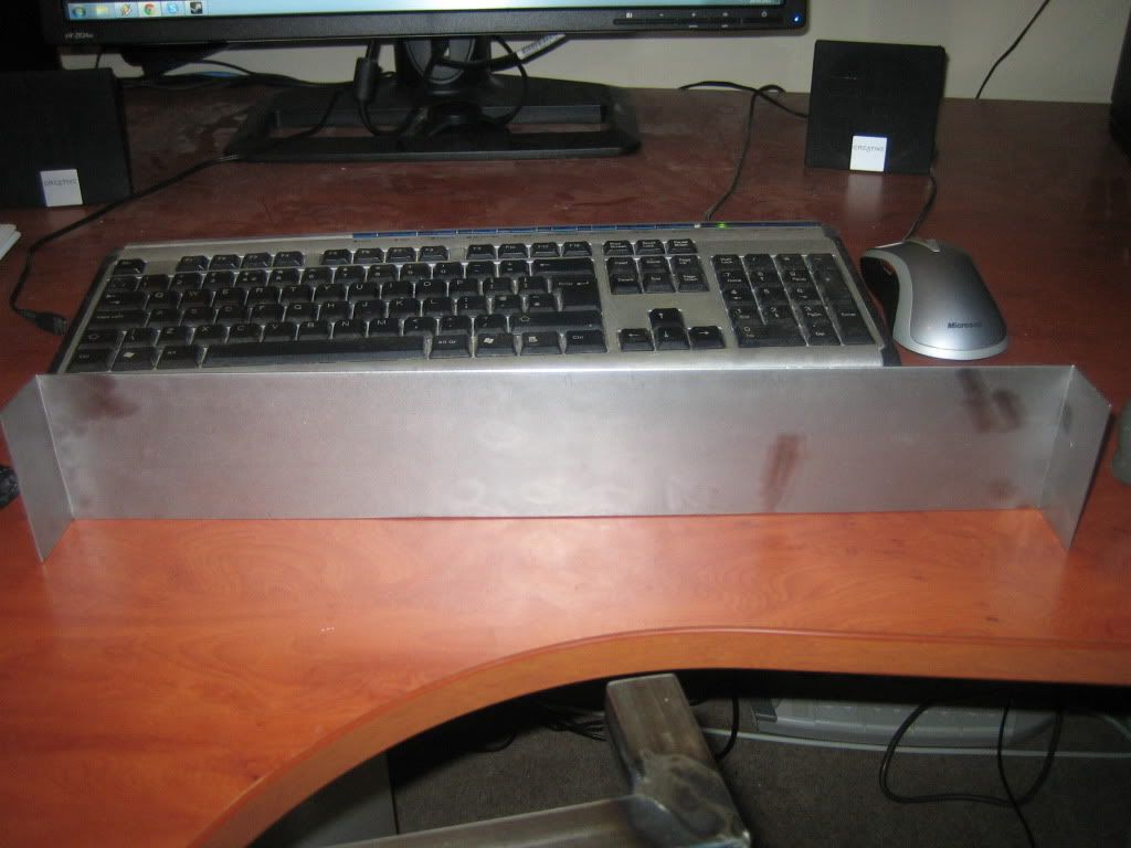
Got a little bit done tonight. Decided to make the last part of the rad mount. I cut a piece of sheet steel to fit on top of the box section, scored it with the dremmel and bent it to fit on nice and snug.
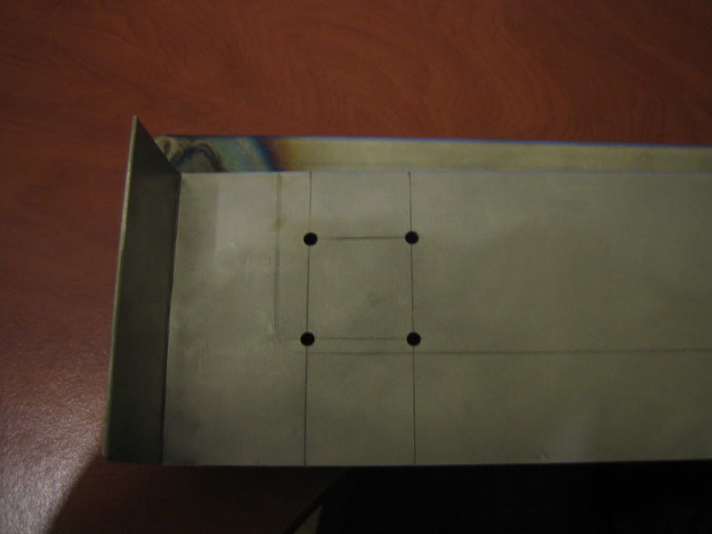
I measured the screw hole positions on the rad marked them out on the top piece of the mount. A bit of drilling and some fine holes emerged. Im using m3 bolts to hold it on so I went for 3.2 mm holes in the mount.
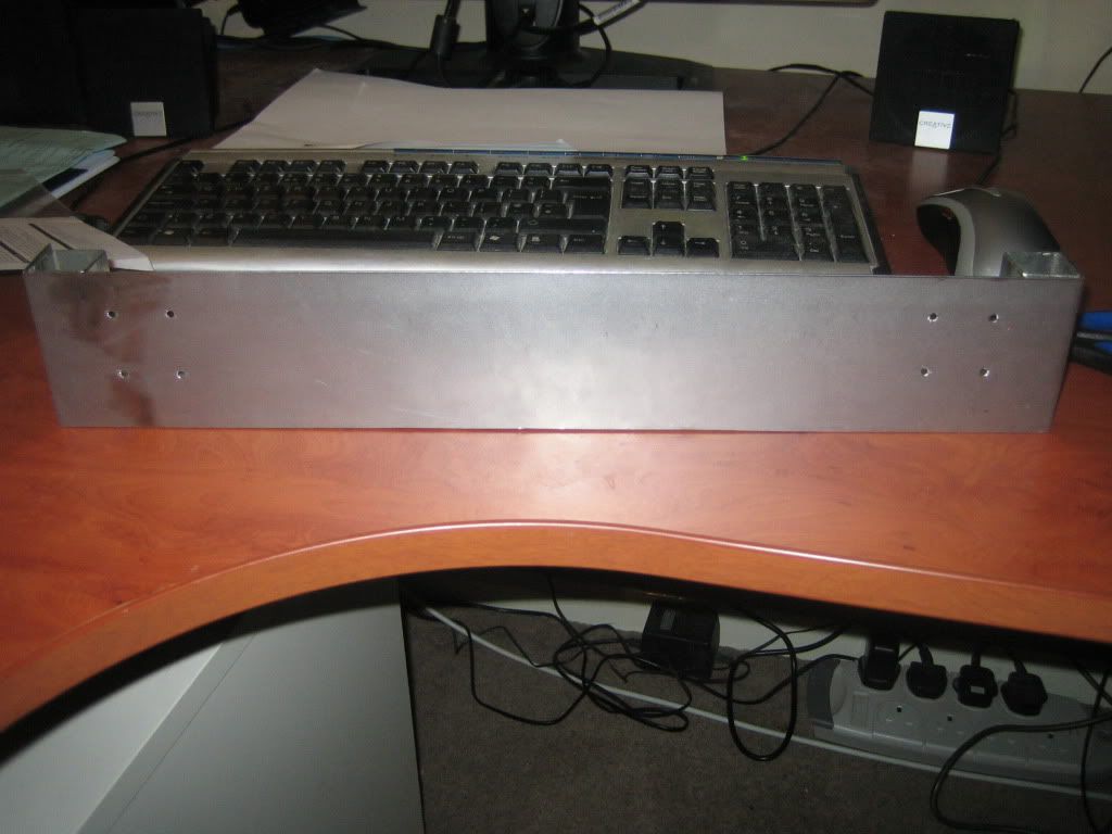
There it is all finished, I gave it a quick grind around the holes to remove any sharp edges so its ready to bolt to the rad as soon as I cut down the ridiculously long bolts that came with it.
UPDATE: 27/02/2012
Not masses I could do this week having no gas to weld with. Did manage to make up part of the mobo tray/component housing. There are two side panels that will attach to a couple of reinforcements at the back so it will be completely enclosed and I will drill out holes as required. I also finished the rad mount, which works quite nicely

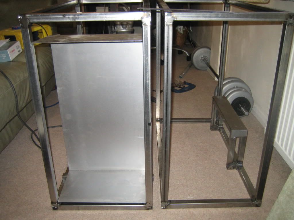
I slightly redesigned the fronts of the two tower sections. Going to have one big window on the component side rather than one medium and one small, I think it looks nicer after drawing it out on the steel.
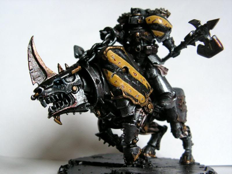
Also been thinking about the theme as a whole, I did want to use purple accents on the black but purple is a bit of a nightmare to get nice shades of and could look awful if I do it wrong. So I was thinking of going further along the WH40K route and using the iron warriors chaos legion as a theme, what do you guys think? For those who aren't 40K nerds like myself, this pic gives an idea of the colours. Its mainly steel/Iron, black and yellow.
UPDATE: 18/03/2012
Firstly I apologise for the lack of updates recently, ive had several other things to deal with recently.
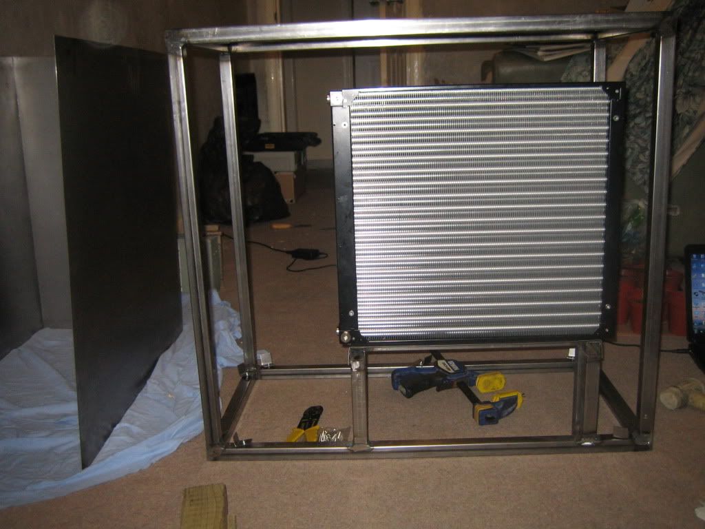
So last time I had just made the rad mount, I cut down the bolts that came with the Mo-Ra so that they wouldn't bend go in too far when used with my mount, thus protecting the fins. I used a wire stripping tool to do this, it worked ok but bent the bolts slightly at the end. As i only have a couple of mm of material to screw into it didn't really matter. So here's the Rad in place!
With the bare steel having been lying around for a few months now superficial rust is starting to form on some pieces. I didn't want this to get out of hand so I really wanted to get the sides fixed on so im ready for painting.
First step was to make some mounting brackets.
I cut some 1 mm sheet into 2x1 " strips using snips. clamping the sides on showed me I needed to only hold a few specific points so these should work fine.
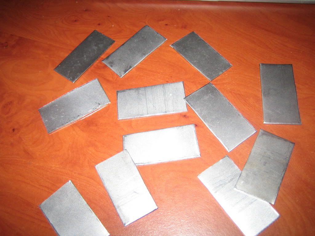
So these need to have a 90 degree bend in them, this is pretty easy to do on small bits like this with firstly my friend the clamp.
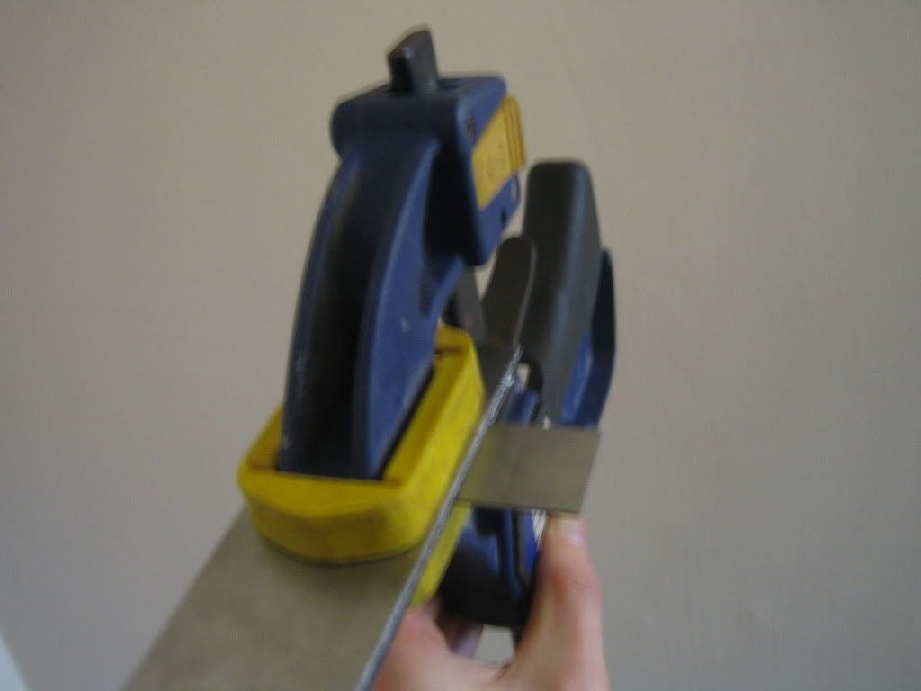
Next carefully apply the tactical force impinging device to the section to be bent.
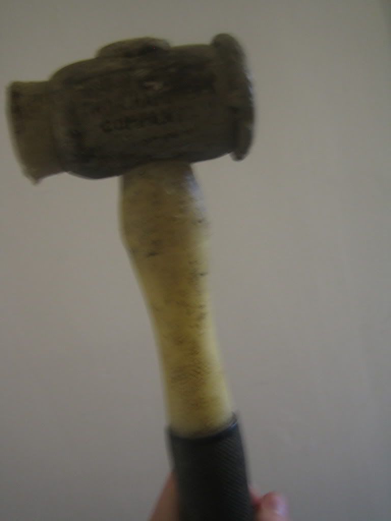
Id call that a success. Apart from the picture quality, thats a disaster I can only apologise for.
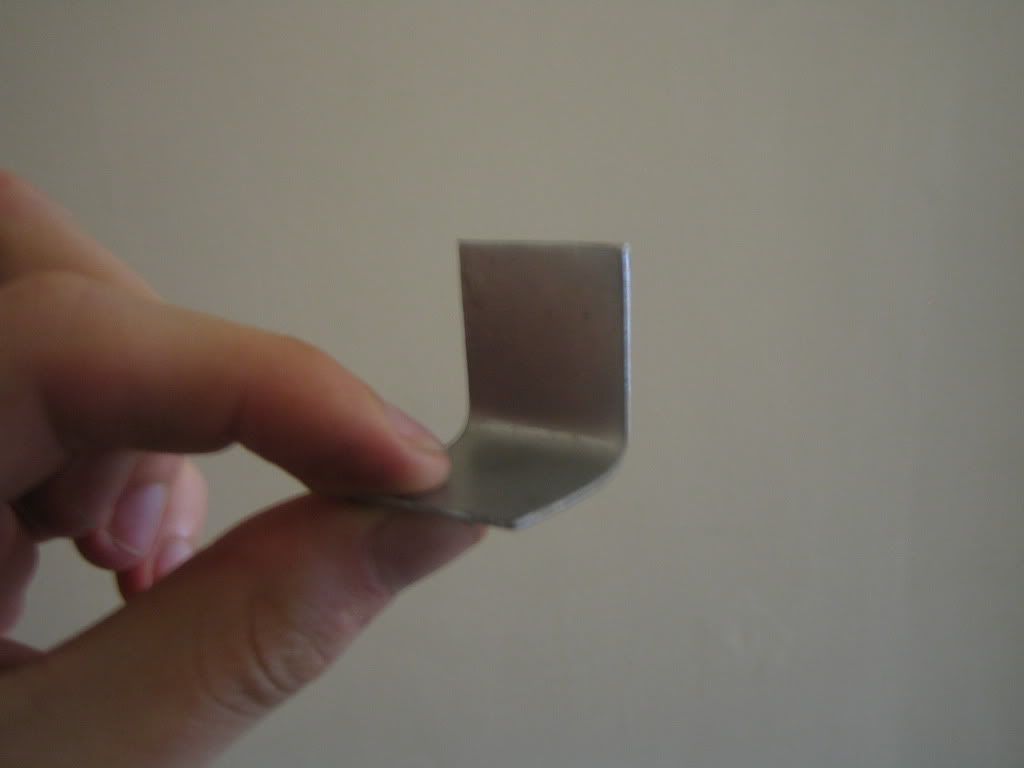
So I forgot to take pics of the next parts but they weren't that exciting anyway. I drilled a clearance hole in each of the brackets and clamped on the sides. I used the brackets to mark the hole positions required on the frame to bolt into. Next the sides came off, drilled out the clearance holes and welded nuts over the holes.
The brackets were bolted to the frame and the sides clamped back on. The other side of the bracket was then welded to the sides.
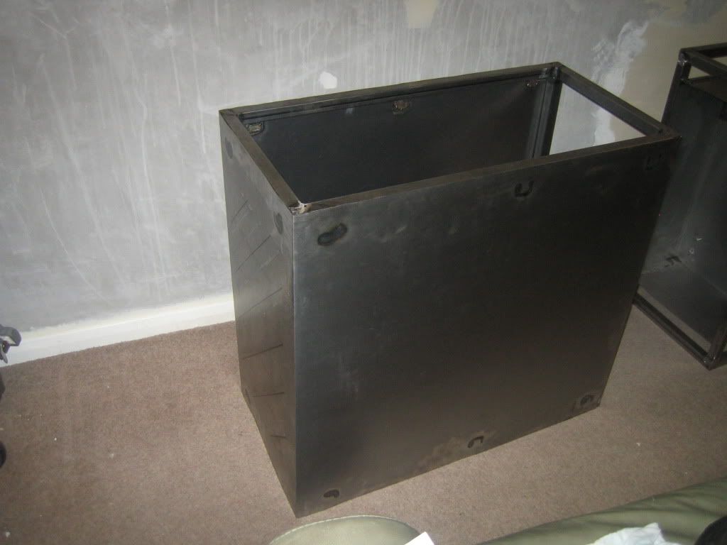
Heres the result. There is some weld penetration I need to grind a little and smooth out but nothing serious.
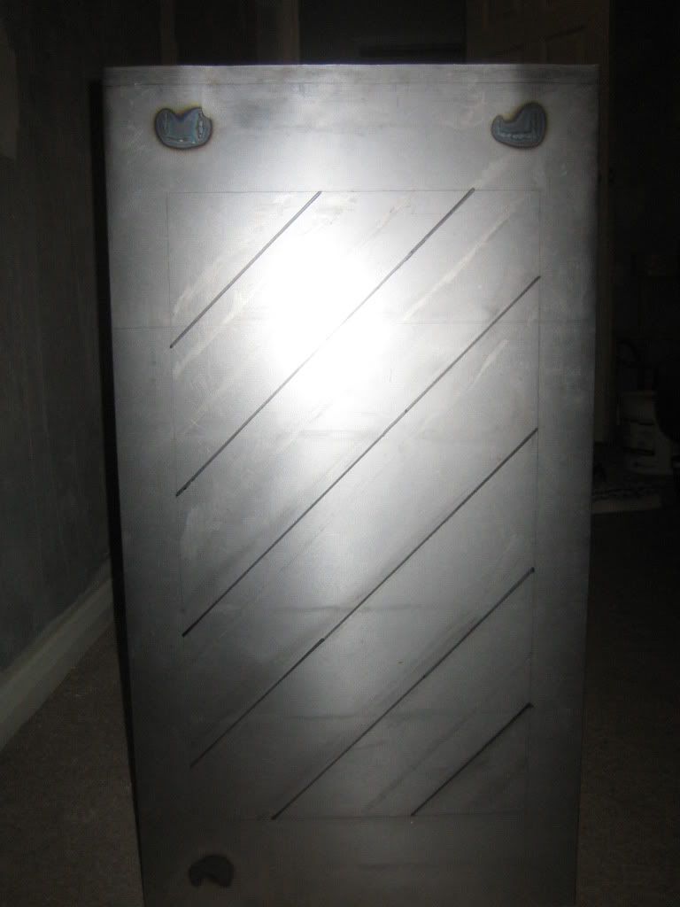
The front section I wasnt sure what to do with on the rad side. Im thinking of cutting out this diagonal/shevron type pattern and having a tall thin res I can make out of acrylic behind it. Could look interesting if I do it right? Could use some input here if anyone has any thoughts.
Ive also made up a steel box to hold the components in the other tower section. This is comprised of 3 pieces of sheet steel wrapped around each other and a box section brace at the back. Looks a little mess right now but the back will be hidden.
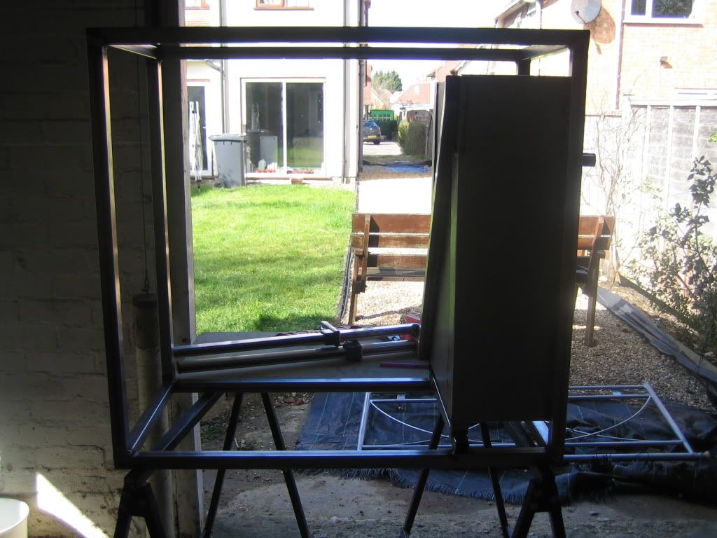
This is the front view. After filling/painting I think this will look quite good. Just need to make a few cut outs for cable routing and cpu etc.
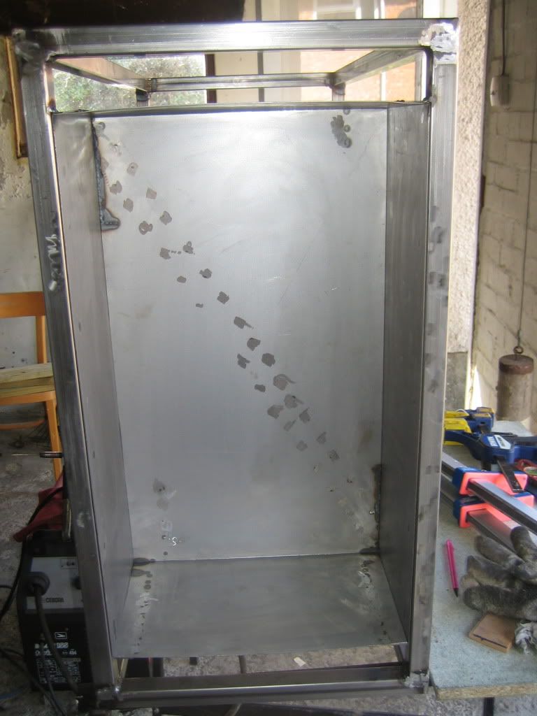
Well thats it for now. Hopefully I will get a fair bit done next weekend, mabey even some painting!
UPDATE: 02/04/2012
So haven't had an update for a while due to upheaval and loss of camera to the ex but now I have a different camera! Even older than the last!
Some of the bits that I didn't get a chance to include photos of were the re-bending of the sides and changing of the mounting brackets. That took about a day but really improved the shape I think so was worth it. I also made the cut out for the rad using the jigsaw, went well just made up a jig and followed it for lovely straight cuts.
Since I had this great new hole to be proud of I decided to cut and bend the mesh to sit in it. After I cut it to size with some snips I clamped it down and bent some kinks into it so that it would sit into the cut out nicely. The clamps and hammer method again proved to be effective.
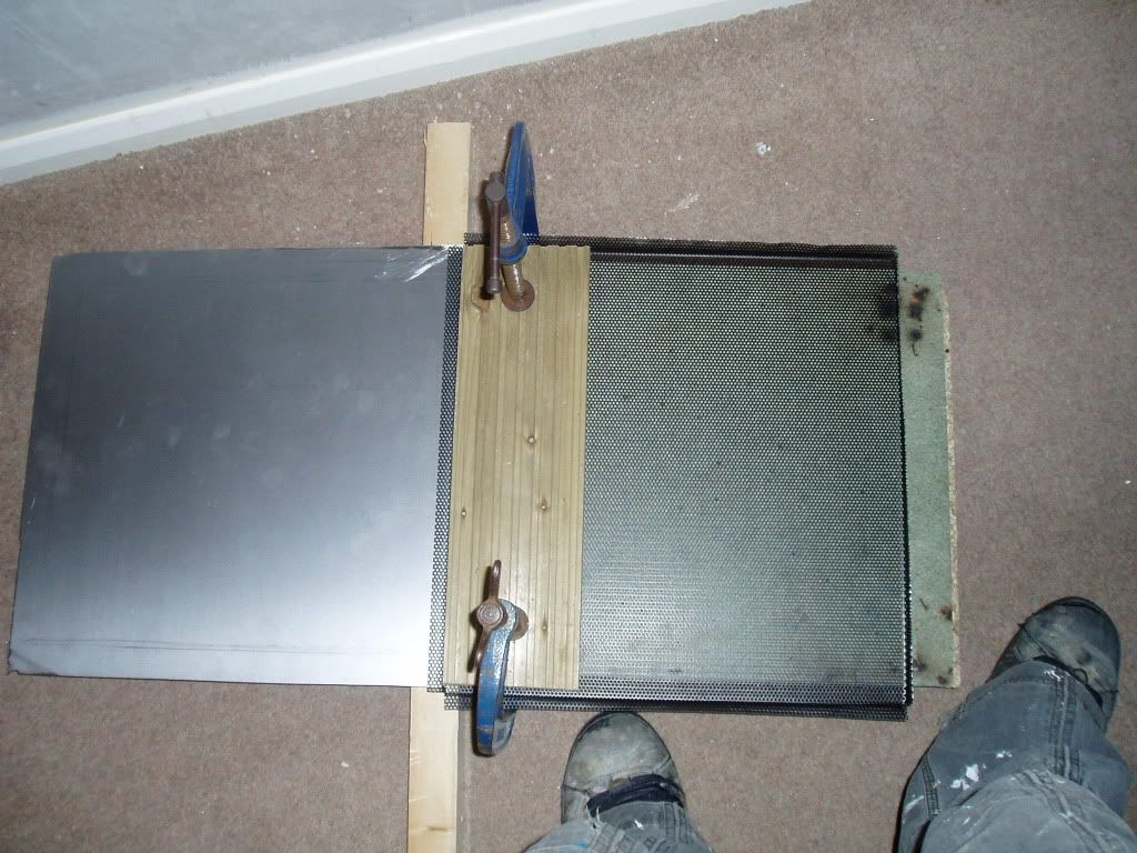
A lot of forcing, swearing and a tube of aryldite later the mesh is in, looks pretty messy but the excess cleaned off fine with a stanley blade. Im quite proud of this bit, starting to look the part now rather than a poorly built box

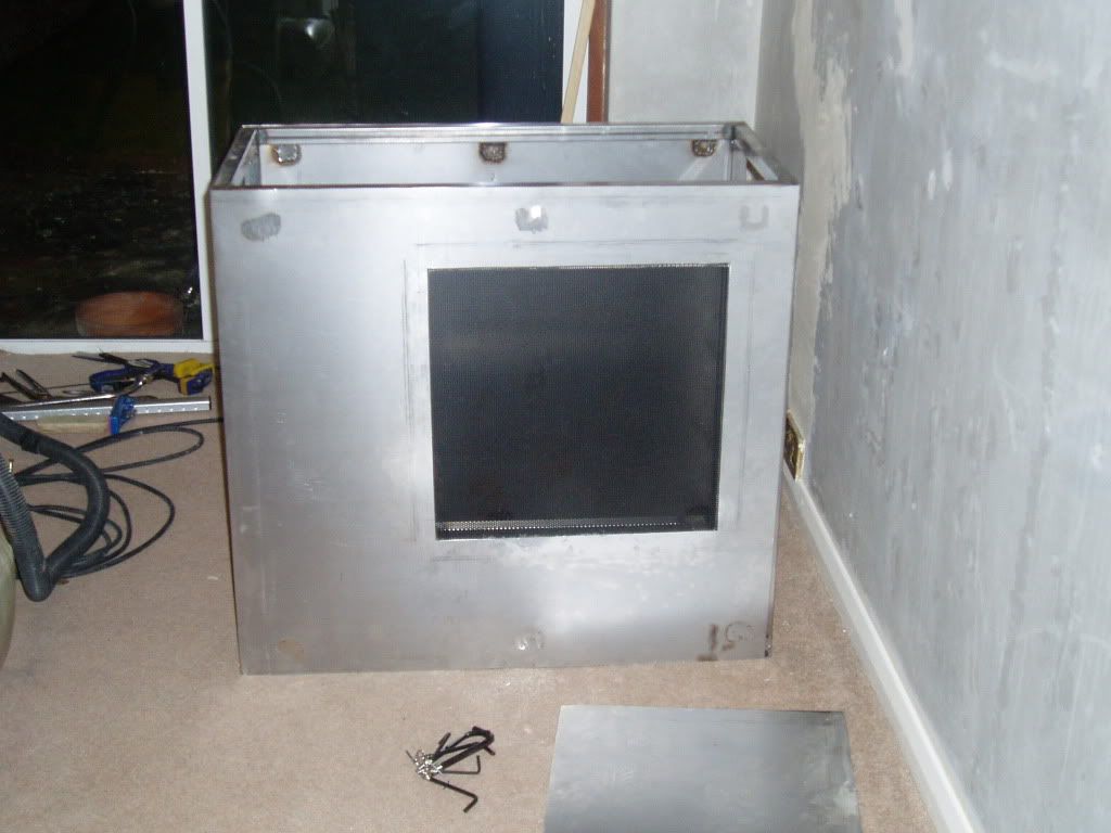
After thinking it through some more I decided to ditch the chevron pattern in the front and keep things simple. I have some ideas for stuff to do on the inside to make the view interesting. So ignoring my pattern I drilled the corners out to let the jigsaw in.
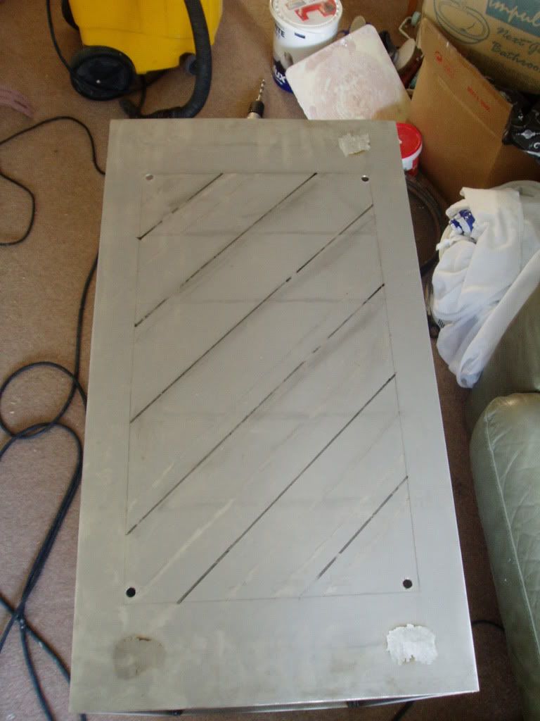
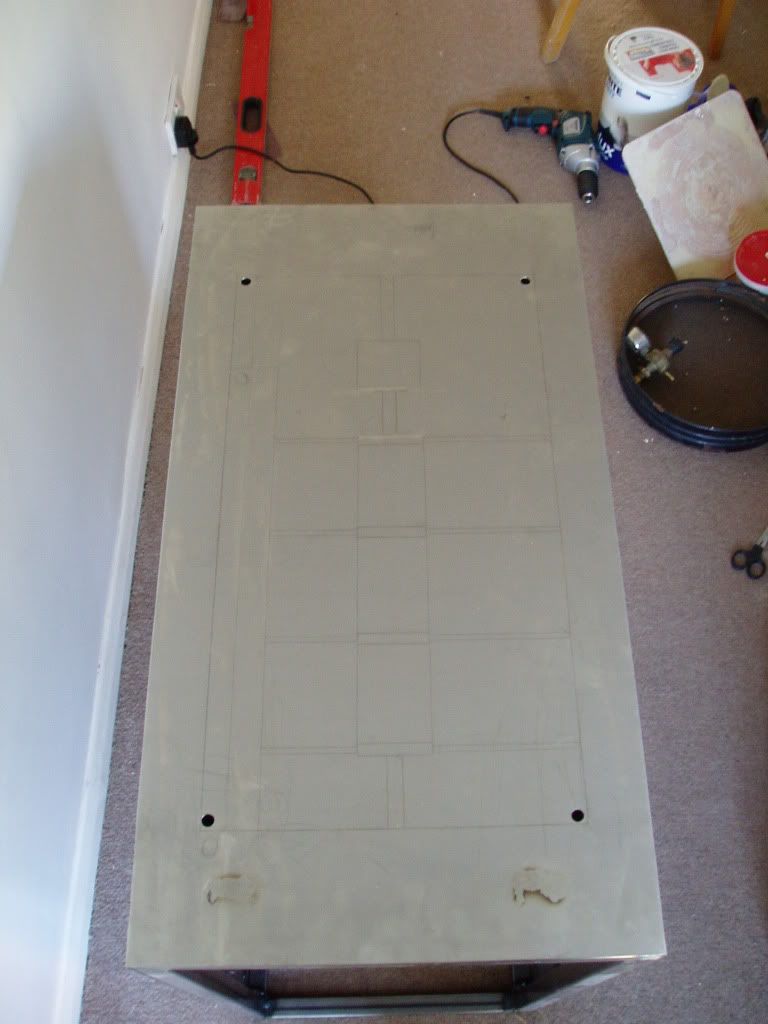
Same again on the other one, you can faintly see some of my planning for what is going to be happening on the radiator side of the desk.
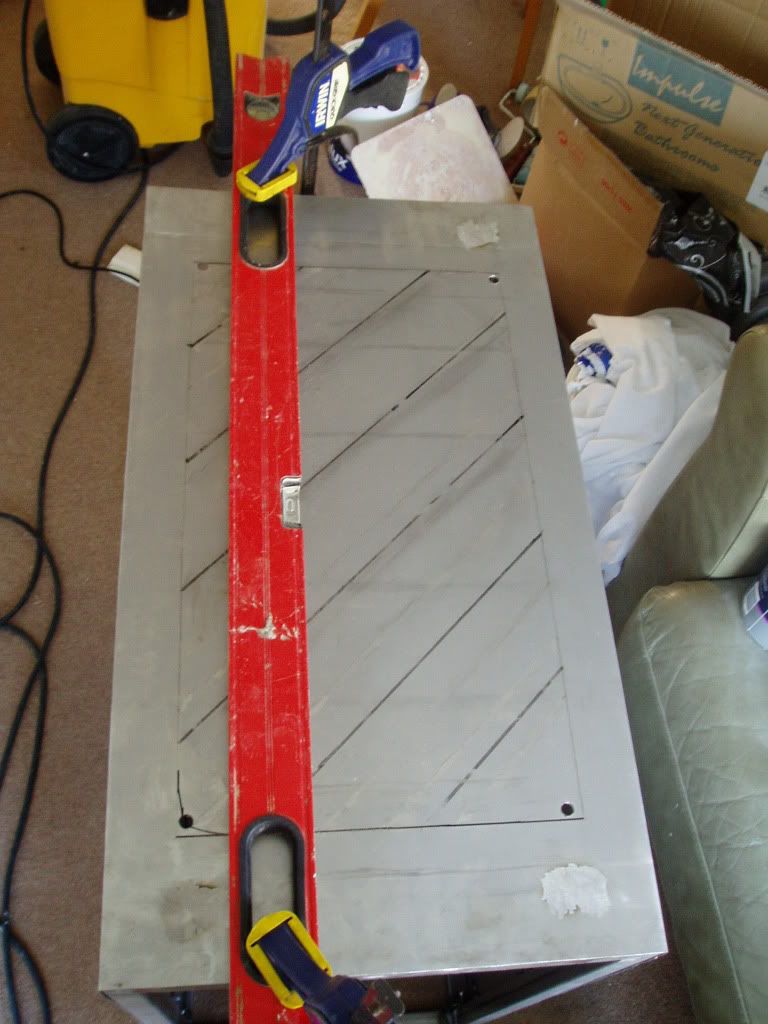
Next I clamped down my level so that the jigsaw has to follow the line I drew, didn't fancy doing this free hand.
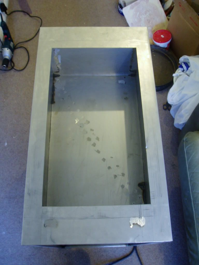
Some jigsawing, a broken blade and cut face later we have a fine hole leading to the main compartment where the kit will live.
Finally just a quick shot of the two together to give an idea of how things are looking overall.
Pretty happy with how this is shaping up now if i do say so myself!
Yes those walls are freshly base coated, very nice eh? Been multitasking this weekend!
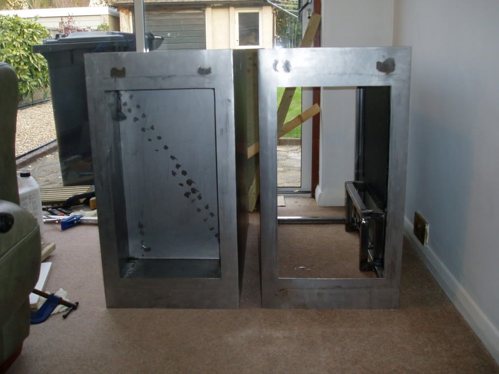
Need to start buying components now so i know where to drill for cable routing, stand off positions etc. Why do I have such expensive interests....
UPDATE: 08/04/2012
I was going to be a load of components this week but decided against it, going to just get everything all in one go when IB comes out.
Firstly. Huston we have standoffs!
I hope I have got my measurements right here as I didn't have a spare motherboard to use as a template...
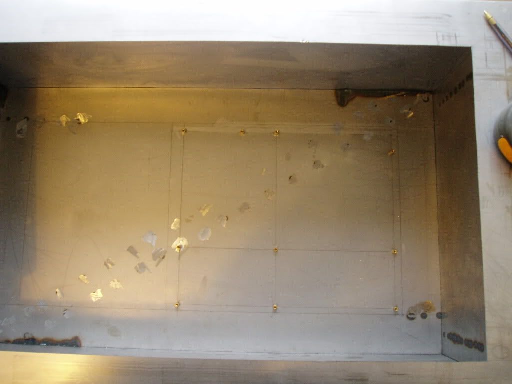
Next PAINTING, I have been mentioning this in every update for about a month but yes I have finally started. Go easy on me here as this is the first bit of spray painting I have ever done.
So here is the bare metal, sanded with 400 grit to get rid of the rust.
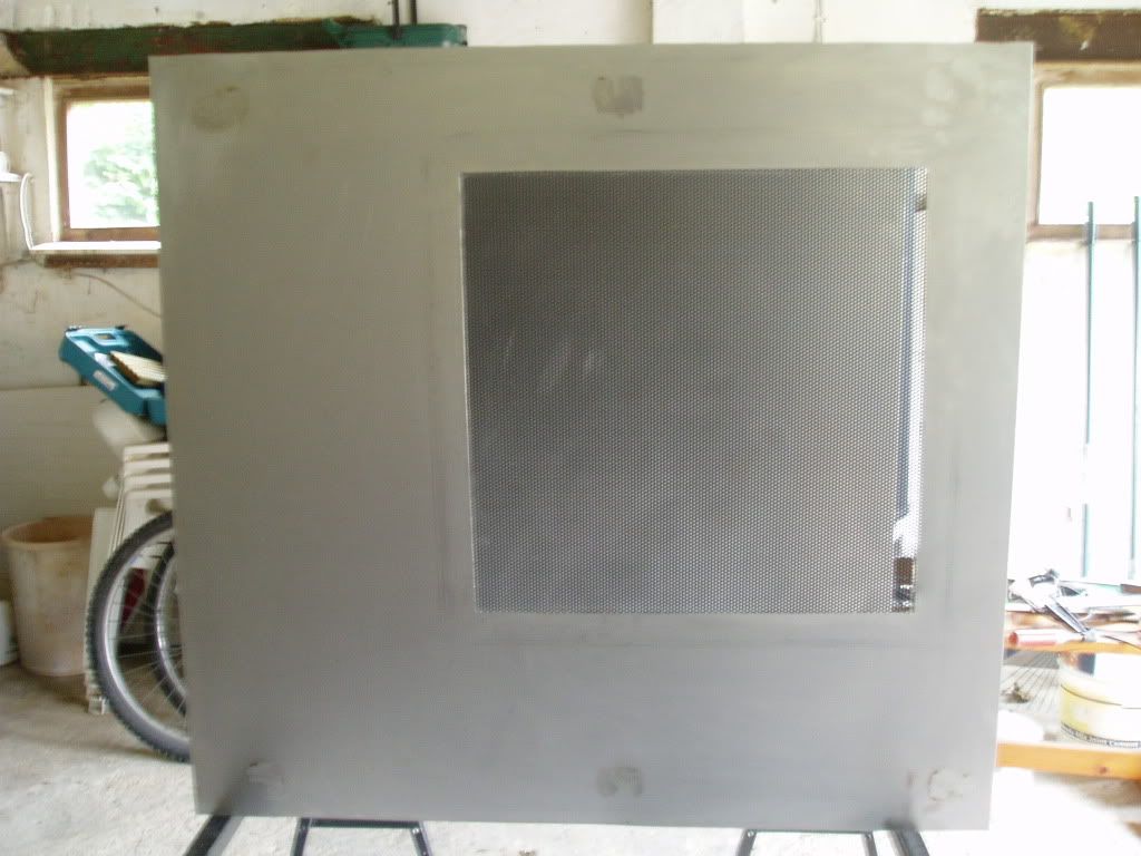
Next I put on a thin layer of acid etching primer to give the paint something to stick to.
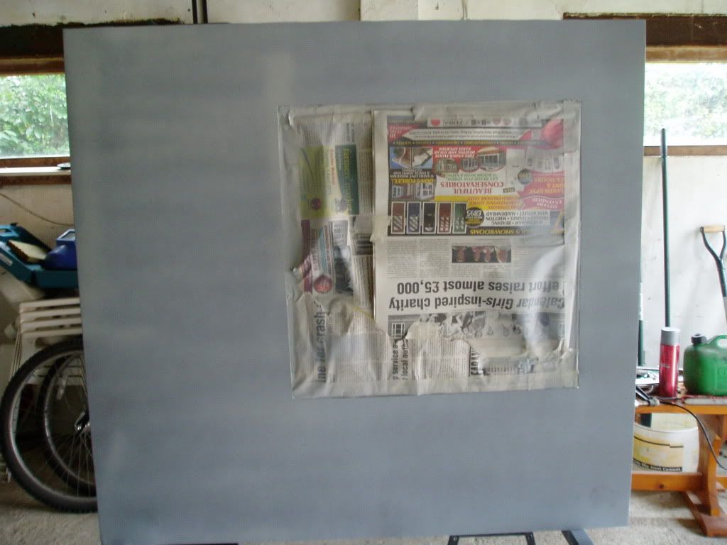
Next I put on a couple of coats of filler primer, the metal has a lot of small scratches and this did a great job of completely covering them. Its very...yellow...
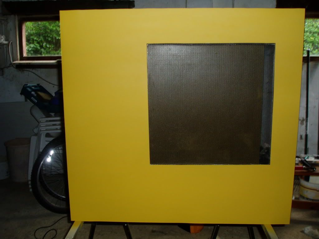
Front
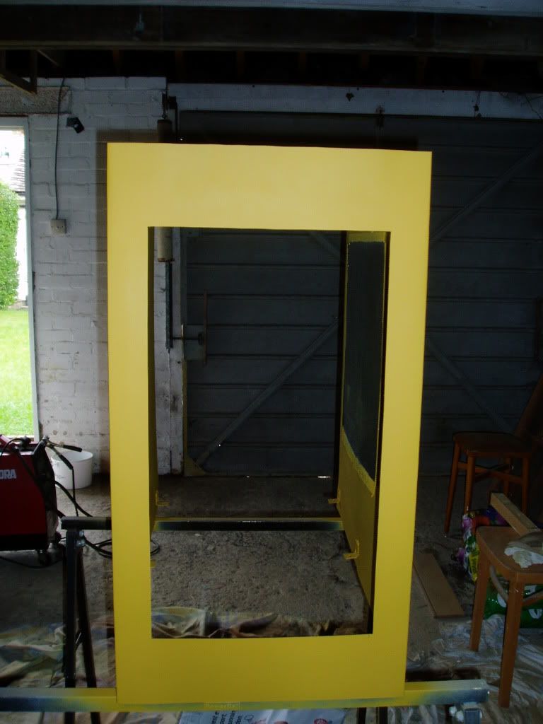
Side 2
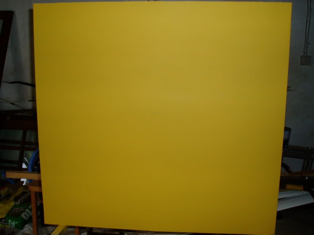
I greatly look forward to sanding all of that down...
It dawned on me the other day that I would need some air flow to keep the "dry" components cool so whilst the paint dried I started on a couple of holes for 120 mm fans.
As i don't have a 115 mm hole saw and they are ~£30 I decided to go for the joining up drill holes method. First I marked out the outline for the hole on the component housing. The inner circle marks the position of my drill holes.
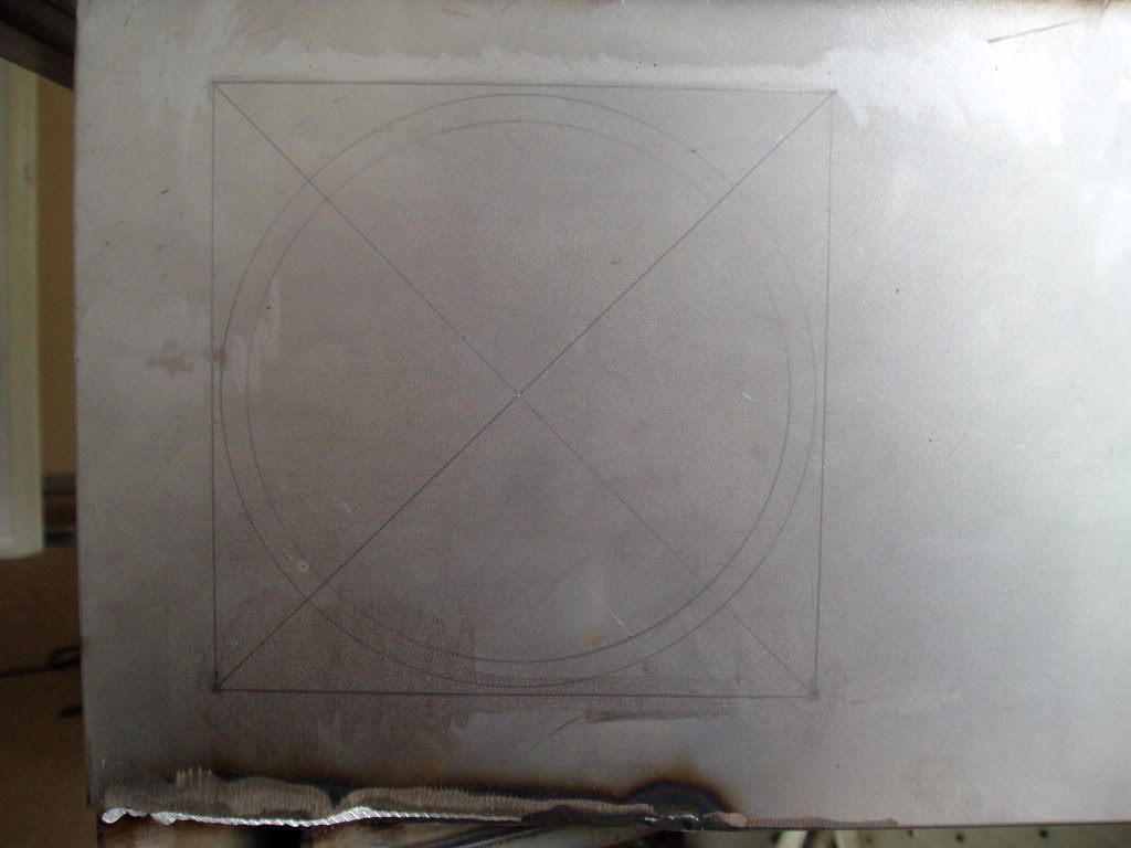
I centre punched and drilled out some small holes to start with so that the bigger frill bit would sit in exactly the right place. Those with a keen eye for detail will note that there are two sizes of hole. My 2.5 mm drill bit pretty much exploded so I was forced to use a 3.5 mm. I guess that's what I get for spending 30p on drill bits...
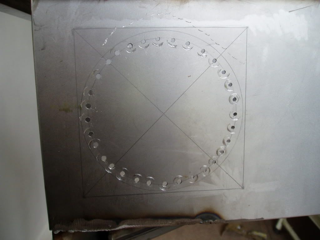
Forgot to take a picture of the next step but all I did was re-drill the holes with a 10mm bit so that at they touched the outer line at the very edge. After that I just joined them up with a hacksaw blade.
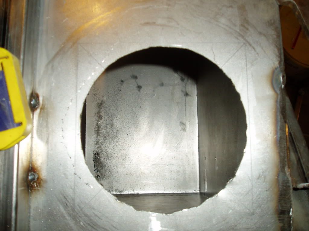
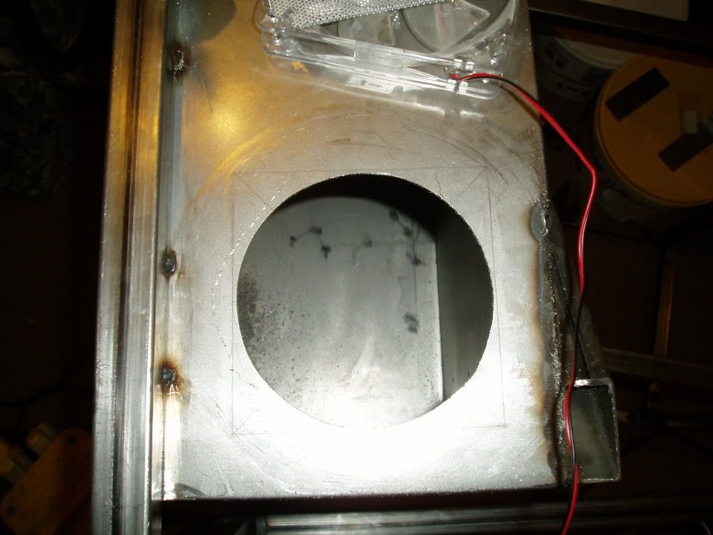
After a bit of filing...
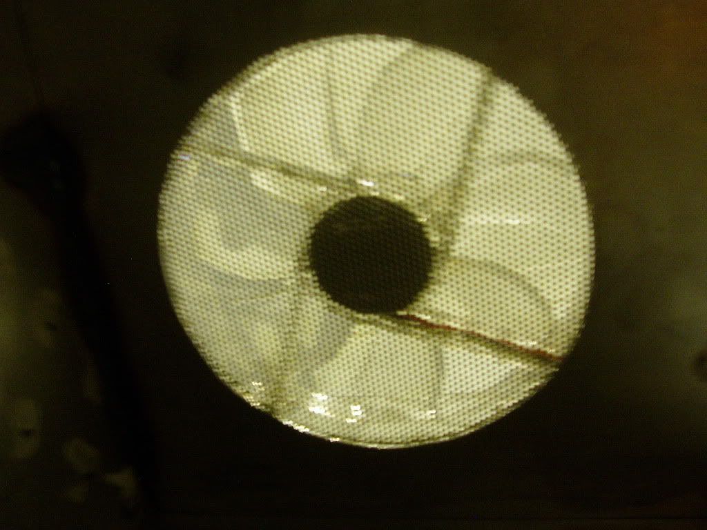
At this juncture my camera became stuck in potato mode and refused to take a decent picture. However this is some mesh i pulled from an old case showing how the inside would look in an alternate, out of focus universe.
Finally the outside with a fan in position. It fits nicely between the two layers of sheet as the box section is 25.4 mm across.
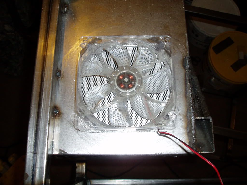
Now I need to make the corresponding hole in the casing and repeat the process on the opposite side of the housing. The air flow is diagonally up from the bottom right to top left across the motherboard.
I have a fair bit of free time this week so hopefully there will be plenty of updates with more painting and hole cutting.
UPDATE: 16/04/2012
Carried on with the painted casing first, sanded it down with some 400 grit to get it nice and flat and filled in a couple of dents/scratches to make it lovely an smooth.
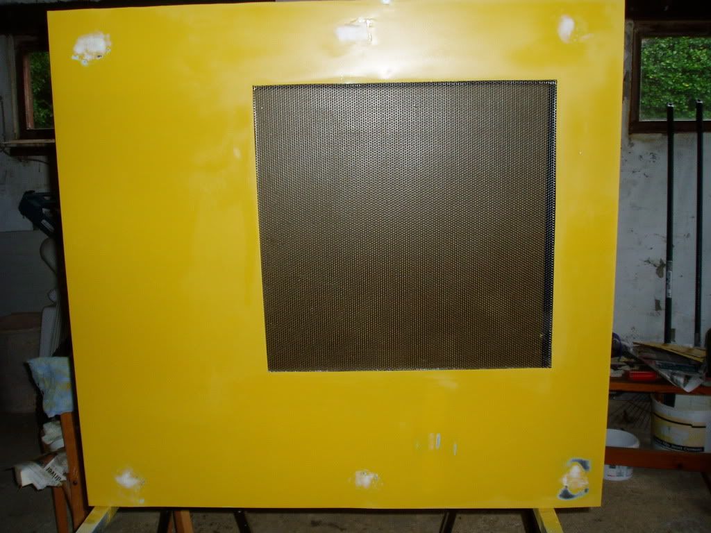
After so many comments about the yellow I thought I would clarify the direction im going with the main colour and get on with it. So here we are, this is three coats of black gloss, still drying in the pic but you get the idea. So just to clarify, its going to be black allover with the steel/yellow coloured areas of interest. Stuff like heat sinks, coolant etc. Going to leave this piece alone for a week, mabey two and then get on with the sanding when im sure its completely cured.
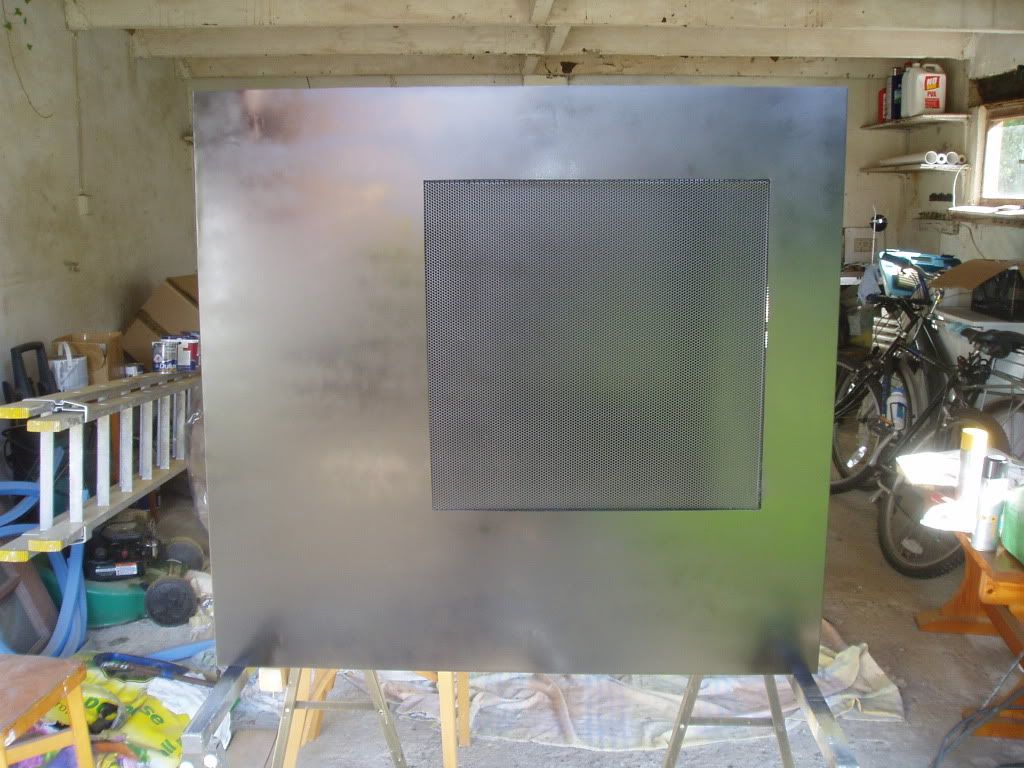
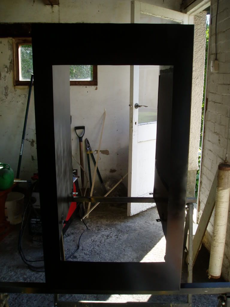
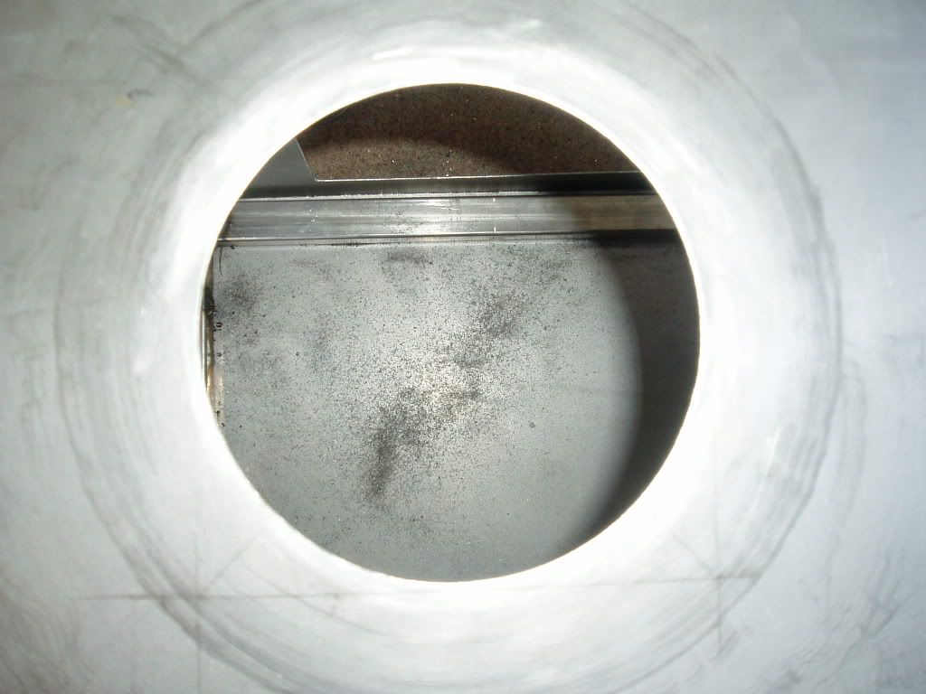
Im getting good at this hole cutting now that im down the last two...here is one of the two that will match up with the ones I cut in the housing. I only drilled a couple of holes this time and cut the circle using a jigsaw, worked a lot better than the pepper pot method. Just tidied it up with a file and some 400 grit, pretty happy with this one.
Same again on the other side and did some sanding/filling where needed to get this one ready for painting.
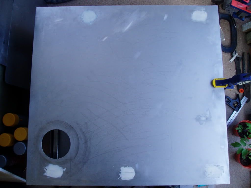
Didnt exactly get masses done, but I was literally waiting for paint and filler to dry for most of the time so couldn't do much. I have violently edited my casing mounting brackets with a hacksaw and a hammer to make the desk easier to get apart and that took a fair bit of time too.
UPDATE: 15/06/2012
So after quite some time without an update I am finally back with some fun stuff to show! Camera back in action and mod progressing again!
Mounting points were made in the housing according to the numbers in the ATX specification, Having welded the standoffs in place I decided to check ( hope ) they were right.
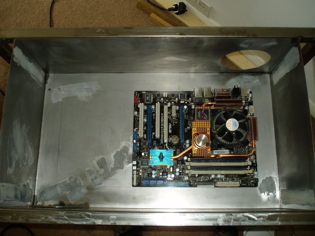
Turns out they were, old mobo is looking a bit dated but she has served me well. Now she gets to help make a home for the successor.
To carry on from here I really needed some parts so I know where to make holes and what sizes mounts etc need to be so here is some rather expensive shopping that has arrived recently:
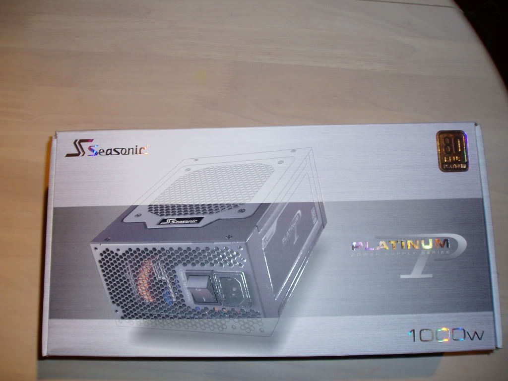
Seasonic p1000W, very overkill for what is in this rig at the moment but there may or may not be some extra power draw from other things I am thinking of adding so best to play safe.

If no other reason was enough, the fact that the psu comes in a velour bag is enough to convince me that it was a fine purchase.
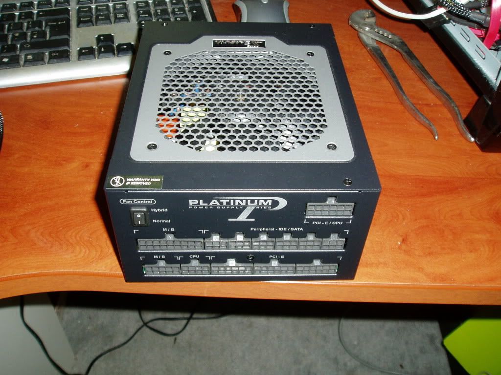
There is the unit its self, looks really good I think, shame it wont be seen in the rig...
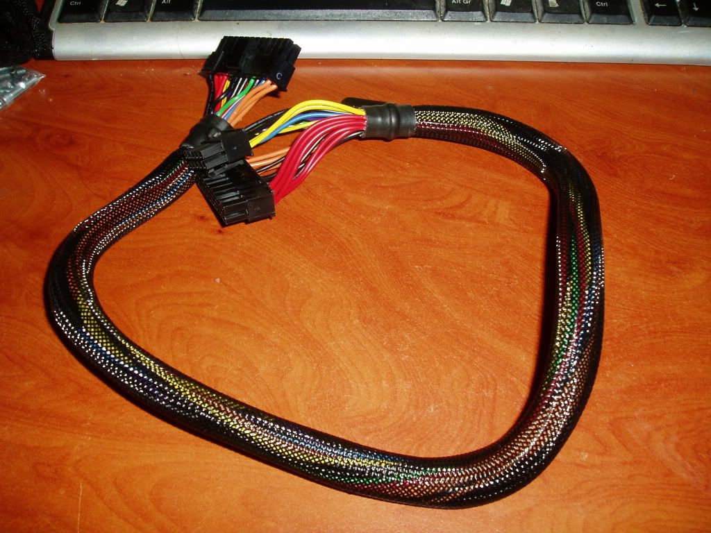
Finally the cables/braiding for anyone interested. The wire its self is 16 AWG for the 12V connections and 18 AWG for the others, so that is a definite plus for me. The braiding is....awful. Seasonic and Enermax both really let them selves down here, I would expect more from a premium product really. However not an issue for me as I will have to extend every single cable anyway so these wont be seen.
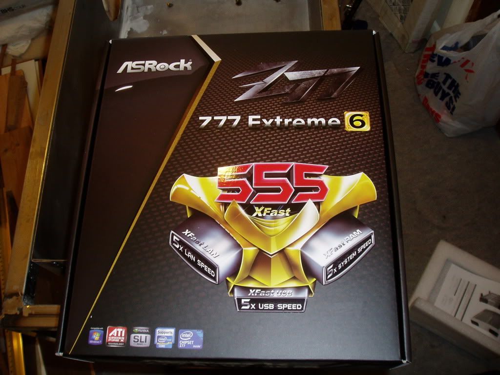
Next up is the mobo, I went for this one as it has some good reviews, well priced and matches my colour scheme well. I think Asrock have really upped their game for 1155 and are starting to produce decent stuff.
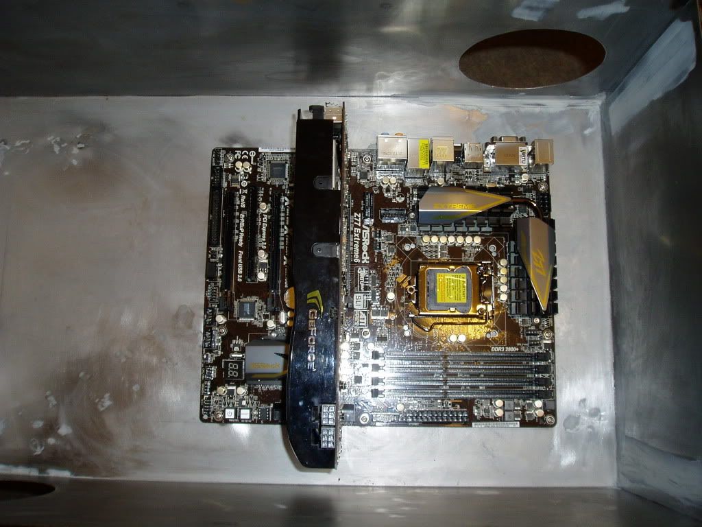
Here is the new board in the housing with my old gpu. Doing some test fitting to see where I will need to add covers and drill holes to route the cables and pipes. I think the board looks pretty sleek and should fit in nicely with my theme.
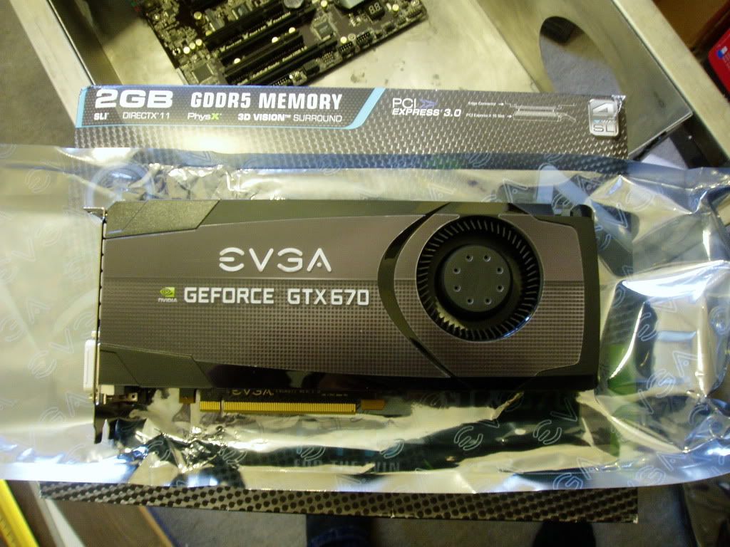
Then there is my EVGA gtx 670 FTW edition. After a lot back and forth I went for the 670 as it seems to represent good value for the performance level. I went for this particular one as it uses a black gtx 680 pcb, allowing me to use 680 waterblocks and not ruining my build with one of the horrid blue pcbs.
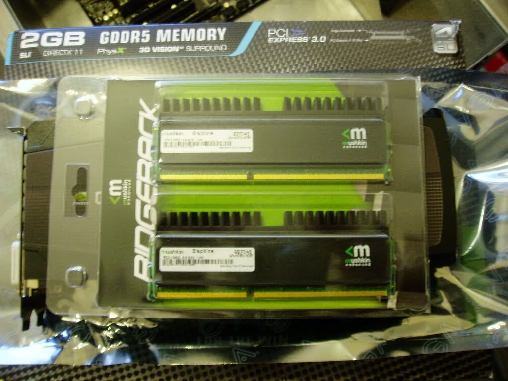
Then we have a particularly poor quality picture of some ridgebacks ( 8gb @1600 MHz ). Again these should fit nicely with the build. Nothing more to say here really, mushkin ram has served a few rigs ive built well so im sticking with it.
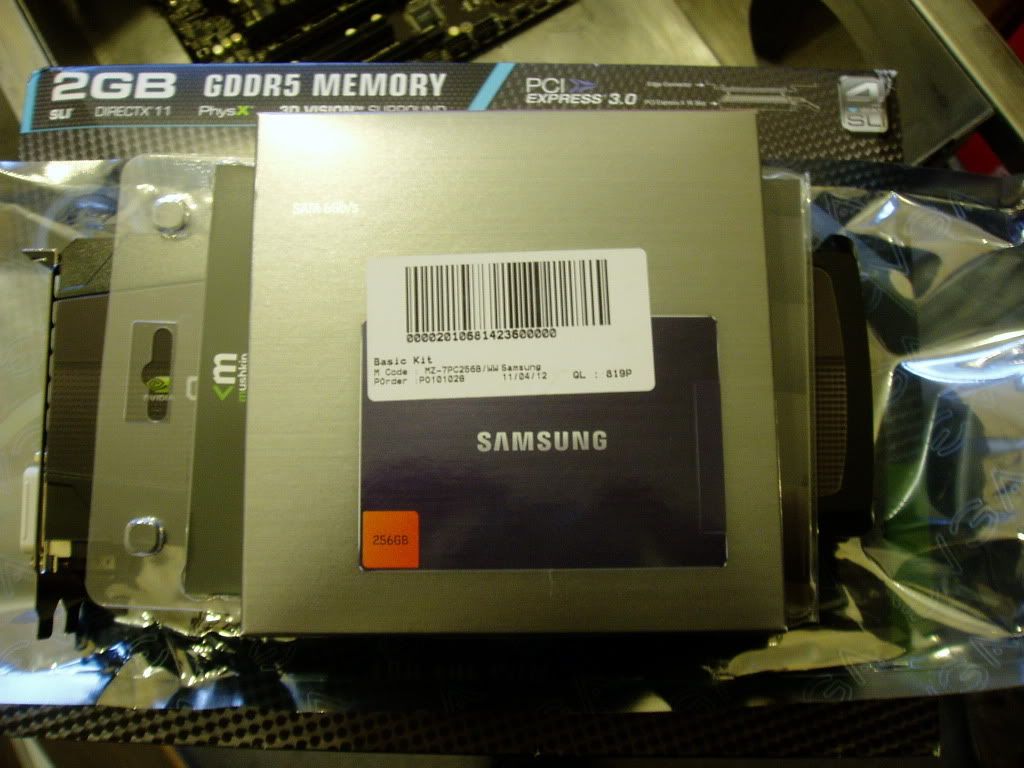
Samsung 830 256 gb SSD. Used one of these in my brothers rig and it seems great, nice reliable brand who manufacture their own flash, low return %, nice and fast. All good, again love the way it looks, will fit in nicely.
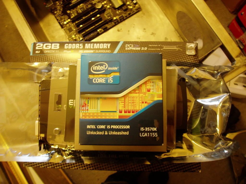
3570K, seemed the best choice for me, I don't really do anything that would benefit from hyper threading.
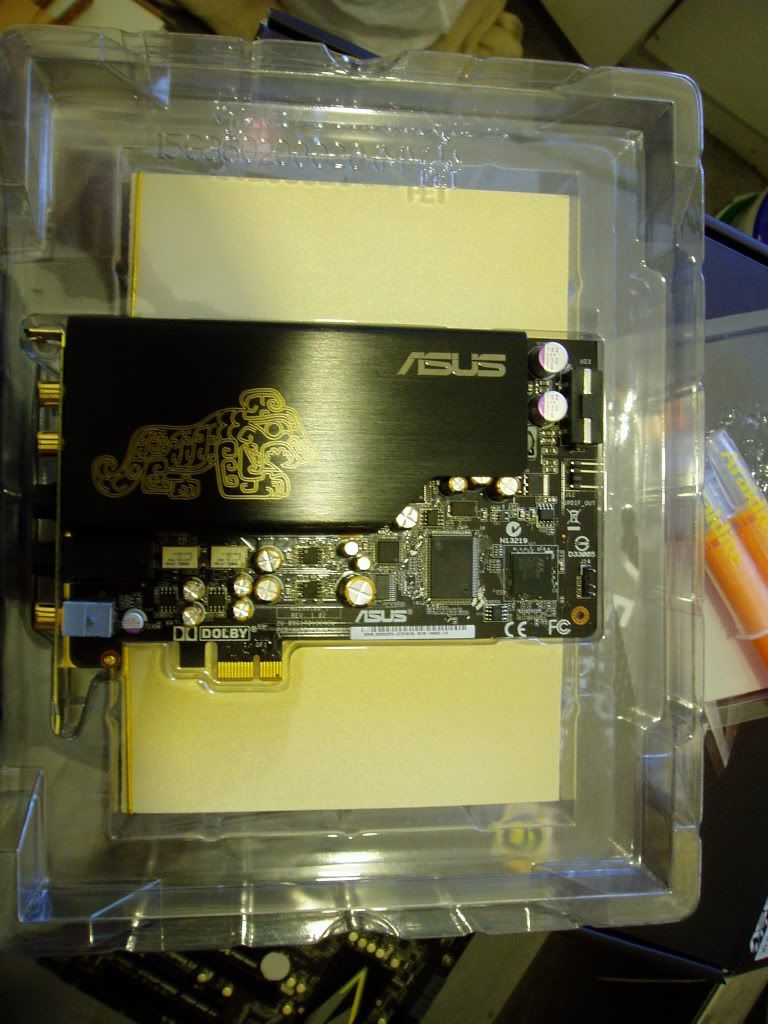
Had this already but its going in so didnt want it to feel left out. Asus Xonar Essence STX, made the biggest difference to my enjoyment of music, movies and games of any other component I have ever upgraded.
So yeah, thats my latest update. Not too exciting in terms of progress I know but I will have some more of the desk its self soon I hope. I will be ordering my fittings and pipe soon so that I can begin routing that and hopefully this whole project will start to take shape!
So basically I wanted to make my Rig into something a bit more unique and give myself a bit of project to get into, hopefully finishing around the release of IB.
The inspiration came from the LEP desk and my visit to LIT, where I saw the Scan Swordfish.
Here is a hastily made model of the kind of thing i'm going for.

The two tower/leg parts are going to be where I house all the components and at the moment I think the fronts will be windowed and I will leave the top solid. The desk is going to be water cooled partly because getting decent airflow would be a nightmare but mostly because I want it to be quiet and pretty
Its possible that I will also build my monitor in so that it rises from the desk in a swordfish like manner but I will have to see how im doing for money at that stage as im on a tight budget and have not been sponsored.
Its going to mostly be made of steel box section and sheet as im bored with working with wood and it should make for a pretty unique look.
This combined with a reference to my username is where the project name came from, geek points to anyone who gets it!
Top will probably be MDF.
Components:
CPU: IB (will choose specific model after I see some benches)
Mobo: Will have to wait and see.
GPUs: At the moment im thinking 7970 but will see what the state of play is when I get to that stage both in terms of cash and other releases.
HDD: Already have a 1TB seagate drive
SSD: Probably something along the lines of a Corsair force GT, will see how pricing is closer to the IB release date.
Soundcard: Already have Asus Xonar STX
Monitor: Already have HP ZR24w (ZR30w or U3011 will probably remain dreams )
PSU: probably 1000W Enermax Platimax
Watercooling parts:
Pump: D5 Vario with bitspower top
CPU block: XSPC Raystorm.
GPU blocks: cant say yet
Res: Custom acrylic res
Tubing: Thinking of trying to do some rigid tubing for something a little different, perspex perhaps.
Fittings: Going to have to see how my perspex idea pans out.
Rad: MO-RA3 pro 9x140 (I want this to be quiet as poss)
fans: Noiseblocker PK2s probably. Mabey a couple of scythe GTs to give a little airflow around the components.
Colour scheme is black, silver, hint of yellow perhaps. Iron warriors colours essentially.
Steel delivered

A borrowed Cebora 155 MIG welder. This is the first time ive ever tried welding so it will be an interesting learning experience, possibly a frustrating one but interesting none the less.

Ive cut the box for the first of the towers, its all 45s for strength. All cut with a hack saw by hand, very tedious.

My first attempt at welding, seems to have come out alright. The bottom section went together fine, only tacked the uprights so I can get them somewhere near square. It would seem the welder is too powerful for me to create continuous beads of weld even on the lowest setting so im just taking one next to the other.


After a solid weekend of working this is what I have to show for myself.

Ive put it next to my HAF-X to give you an idea of the amount of space I will have to work with in each of these towers. The welds have been grinded down on the sides so that I can get the sheet metal on nice and flush. It seems to be strong, it can take my weight so it looks like my welds are good enough.
I will be continuing each weekend so hopefully this topic should get updated at least weekly.
Please let me know what you guys think, advice/criticism is welcome so don't hold back
UPDATE: 29/01/2012
The first tower part seemed to go quite well so this time I have been a bit more thorough in my documentation of the process now that I know it works.
Step 1 was to mark the 45s on the box section I had roughly cut to size. The compass finds its first use since secondary school as a scribe.

Next a bit of cutting with the hacksaw, tried a few other tools but doing it by hand gave the most precise cut even if it did take forever.

I cut the opposite sides separately so that I knew I was getting a good 45 all the way through.

Cutting along the final side without meandering around proved to be a bit awkward so I just cut in a little on either side and used pliers to bend the off-cut until it snapped off.

A little filing later and this is the final product. After getting my new best m8 Mr set square to check the angles I repeated this another seven times...

Squaring up a couple of lengths and clamping them in place. I found that the welder exerts a surprising amount of force and will move two parts apart slightly if they are not clamped.

No pics of the actual welding process because I didn't have enough hands and the misses wouldn't come and hold the camera because she doesn't trust me not to weld her somehow. So after all the welding we get to the assembled tower. Only had time to tack the uprights in as it was getting too dark to see but I can finish the welds and grinding off one evening.

Not too exciting an update but the structure is essentially done. After this I can start making the skin, mobo tray etc so things should start to take shape. Might even order the PSU and start the paracord sleeving.
UPDATE: 30/01/2012
Just a quick one, finished off the welding and grinding this evening so now I have two giant towers

UPDATE: 13/02/2012
First update in a while, cutting the sheet steel was a bit of a nightmare with my little grinder so this weekend I got my dad to come over and bring his jigsaw. Bought some lovely Starrett fine toothed metal blades, which promptly cut the steel like it was paper
So first we got this 2.5x1.25 m sheet onto my improvised bench, which I was glad for some help with, it is heavy, bendy, unreasonably large and unwieldy all at the same time...

Sometimes the things you assume will be straight forward turn out to be the most difficult, this was the case with marking a straight line. My scribe ( ok its a compass but shh..) made a nice thin line to follow so the cut was precise, except it was difficult to see. So we tried going over it with a pencil but that made a thick line and drifted under the level we were using as a straight edge... After rubbing the pencil out we found it had stained the scribed line, solving both problems, inadvertent success is the best kind
My dad models the Festool jigsaw and 80s Ski jacket combo, very big this season.

So after some rather easy cutting steps we have a sheet of 2x1 m, the right size to form to one of the towers. The steel has got a bit scratched up living in the garage but they are mostly not deep at all and I think I can polish most of them out.

And then there were two! They get to move inside now so as to reduce rusting.

I also received a delivery from Specialtech

My new MO-RA 3 9x140 LT, I don't know whether this is a beauty or a beast...or a beautiful beast if there is such a thing?

After minor cajoling I managed to get a lovely young model to hold the MO-RA vaguely in place within the right side tower, whilst desperately trying to stay out of shot.

That's all I managed over the weekend but now that this hold up is out of the way I can get on with the next few bits. Building a rad mount wont be too difficult so that will be done soon. Forming the sheet around the towers will be a challenge and I shall have to think long and hard before I give it a go as I only really have one shot.
UPDATE: 19/02/2012
Right this update was huge in terms of the time it took me but probably doesn't look like much from the photos!
With the Rad here I decided to make the mount for it. So first I cut up the box section with my now blunt hacksaw.

Next I welded together the parts to make the mount easier to assemble. The rad will be screwed to a piece of sheet metal that will bolt to the top piece show in the pic so that I can remove the rad more easily should I need to. The lower parts are legs, yes I know two are shorter...have faith

Back legs are welded in place, the L shaped part gives them more contact area with the ground.

We have jumped forward in time a bit here but I forgot to take a picture at the time

Now to making the "skin" I put one of the frames on top of the sheet steel, marked the bends and scored them.

I have discovered 1mm steel is stronger than I thought...bending it without a break is almost impossible so I decided to make a fault in it to force it to bend when I apply a silly amount of force. I used the dremmel to cut ~1/3 of the way through the steel.

I got a little too into the cutting and didn't notice the huge amount of fine black powder I had got allover the floor....Fearing for my life I looked for something to clean it up without making it worse and found my magnet pen, it actually pulled it all out of the carpet! So assuming the misses doesn't become an OC3D member all evidence is disposed of

I think I got my moneys worth from this disc, time for a new one I think.

Cuts made for both bends, next how to bend something this unwieldy with none of the right tools!

I put some chipboard under the steel and one of the towers on top, in line with the cuts. Next I applied weight, 3 slate tiles and one small person was sufficient.

I got another piece of wood and put it under the side pushed right up to the chipboard. Then I pivoted it against the front corner, which took a surprising amount of force. This only got me to a ~ 45 degree bend.

This was the third way id tried to bend this and had been at it all day so i lost it a bit and decided to...

Enough clamps? seems to have tamed the unruly steel nicely.

Alright if you insist, one more...

Here's the finished product, pretty happy with the bends. Its not quite there but when I decide how I fix it I can probably deal with that.

Got plenty done this weekend, that bending was so time consuming so im glad its done, the project should go pretty smoothly now thats done I think..... I hope.
Next is finish rad mount, work out how to fix the sides and cut out the windows.
UPDATE: 20/02/2012
Got a little bit done tonight. Decided to make the last part of the rad mount. I cut a piece of sheet steel to fit on top of the box section, scored it with the dremmel and bent it to fit on nice and snug.

I measured the screw hole positions on the rad marked them out on the top piece of the mount. A bit of drilling and some fine holes emerged. Im using m3 bolts to hold it on so I went for 3.2 mm holes in the mount.

There it is all finished, I gave it a quick grind around the holes to remove any sharp edges so its ready to bolt to the rad as soon as I cut down the ridiculously long bolts that came with it.

UPDATE: 27/02/2012
Not masses I could do this week having no gas to weld with. Did manage to make up part of the mobo tray/component housing. There are two side panels that will attach to a couple of reinforcements at the back so it will be completely enclosed and I will drill out holes as required. I also finished the rad mount, which works quite nicely

I slightly redesigned the fronts of the two tower sections. Going to have one big window on the component side rather than one medium and one small, I think it looks nicer after drawing it out on the steel.
Also been thinking about the theme as a whole, I did want to use purple accents on the black but purple is a bit of a nightmare to get nice shades of and could look awful if I do it wrong. So I was thinking of going further along the WH40K route and using the iron warriors chaos legion as a theme, what do you guys think? For those who aren't 40K nerds like myself, this pic gives an idea of the colours. Its mainly steel/Iron, black and yellow.

UPDATE: 18/03/2012
Firstly I apologise for the lack of updates recently, ive had several other things to deal with recently.
So last time I had just made the rad mount, I cut down the bolts that came with the Mo-Ra so that they wouldn't bend go in too far when used with my mount, thus protecting the fins. I used a wire stripping tool to do this, it worked ok but bent the bolts slightly at the end. As i only have a couple of mm of material to screw into it didn't really matter. So here's the Rad in place!

With the bare steel having been lying around for a few months now superficial rust is starting to form on some pieces. I didn't want this to get out of hand so I really wanted to get the sides fixed on so im ready for painting.
First step was to make some mounting brackets.
I cut some 1 mm sheet into 2x1 " strips using snips. clamping the sides on showed me I needed to only hold a few specific points so these should work fine.

So these need to have a 90 degree bend in them, this is pretty easy to do on small bits like this with firstly my friend the clamp.

Next carefully apply the tactical force impinging device to the section to be bent.

Id call that a success. Apart from the picture quality, thats a disaster I can only apologise for.

So I forgot to take pics of the next parts but they weren't that exciting anyway. I drilled a clearance hole in each of the brackets and clamped on the sides. I used the brackets to mark the hole positions required on the frame to bolt into. Next the sides came off, drilled out the clearance holes and welded nuts over the holes.
The brackets were bolted to the frame and the sides clamped back on. The other side of the bracket was then welded to the sides.
Heres the result. There is some weld penetration I need to grind a little and smooth out but nothing serious.

The front section I wasnt sure what to do with on the rad side. Im thinking of cutting out this diagonal/shevron type pattern and having a tall thin res I can make out of acrylic behind it. Could look interesting if I do it right? Could use some input here if anyone has any thoughts.

Ive also made up a steel box to hold the components in the other tower section. This is comprised of 3 pieces of sheet steel wrapped around each other and a box section brace at the back. Looks a little mess right now but the back will be hidden.

This is the front view. After filling/painting I think this will look quite good. Just need to make a few cut outs for cable routing and cpu etc.

Well thats it for now. Hopefully I will get a fair bit done next weekend, mabey even some painting!
UPDATE: 02/04/2012
So haven't had an update for a while due to upheaval and loss of camera to the ex but now I have a different camera! Even older than the last!
Some of the bits that I didn't get a chance to include photos of were the re-bending of the sides and changing of the mounting brackets. That took about a day but really improved the shape I think so was worth it. I also made the cut out for the rad using the jigsaw, went well just made up a jig and followed it for lovely straight cuts.
Since I had this great new hole to be proud of I decided to cut and bend the mesh to sit in it. After I cut it to size with some snips I clamped it down and bent some kinks into it so that it would sit into the cut out nicely. The clamps and hammer method again proved to be effective.

A lot of forcing, swearing and a tube of aryldite later the mesh is in, looks pretty messy but the excess cleaned off fine with a stanley blade. Im quite proud of this bit, starting to look the part now rather than a poorly built box

After thinking it through some more I decided to ditch the chevron pattern in the front and keep things simple. I have some ideas for stuff to do on the inside to make the view interesting. So ignoring my pattern I drilled the corners out to let the jigsaw in.

Same again on the other one, you can faintly see some of my planning for what is going to be happening on the radiator side of the desk.

Next I clamped down my level so that the jigsaw has to follow the line I drew, didn't fancy doing this free hand.

Some jigsawing, a broken blade and cut face later we have a fine hole leading to the main compartment where the kit will live.

Finally just a quick shot of the two together to give an idea of how things are looking overall.
Pretty happy with how this is shaping up now if i do say so myself!
Yes those walls are freshly base coated, very nice eh? Been multitasking this weekend!

Need to start buying components now so i know where to drill for cable routing, stand off positions etc. Why do I have such expensive interests....
UPDATE: 08/04/2012
I was going to be a load of components this week but decided against it, going to just get everything all in one go when IB comes out.
Firstly. Huston we have standoffs!
I hope I have got my measurements right here as I didn't have a spare motherboard to use as a template...

Next PAINTING, I have been mentioning this in every update for about a month but yes I have finally started. Go easy on me here as this is the first bit of spray painting I have ever done.
So here is the bare metal, sanded with 400 grit to get rid of the rust.

Next I put on a thin layer of acid etching primer to give the paint something to stick to.

Next I put on a couple of coats of filler primer, the metal has a lot of small scratches and this did a great job of completely covering them. Its very...yellow...

Front

Side 2

I greatly look forward to sanding all of that down...
It dawned on me the other day that I would need some air flow to keep the "dry" components cool so whilst the paint dried I started on a couple of holes for 120 mm fans.
As i don't have a 115 mm hole saw and they are ~£30 I decided to go for the joining up drill holes method. First I marked out the outline for the hole on the component housing. The inner circle marks the position of my drill holes.

I centre punched and drilled out some small holes to start with so that the bigger frill bit would sit in exactly the right place. Those with a keen eye for detail will note that there are two sizes of hole. My 2.5 mm drill bit pretty much exploded so I was forced to use a 3.5 mm. I guess that's what I get for spending 30p on drill bits...

Forgot to take a picture of the next step but all I did was re-drill the holes with a 10mm bit so that at they touched the outer line at the very edge. After that I just joined them up with a hacksaw blade.

After a bit of filing...

At this juncture my camera became stuck in potato mode and refused to take a decent picture. However this is some mesh i pulled from an old case showing how the inside would look in an alternate, out of focus universe.

Finally the outside with a fan in position. It fits nicely between the two layers of sheet as the box section is 25.4 mm across.

Now I need to make the corresponding hole in the casing and repeat the process on the opposite side of the housing. The air flow is diagonally up from the bottom right to top left across the motherboard.
I have a fair bit of free time this week so hopefully there will be plenty of updates with more painting and hole cutting.
UPDATE: 16/04/2012
Carried on with the painted casing first, sanded it down with some 400 grit to get it nice and flat and filled in a couple of dents/scratches to make it lovely an smooth.

After so many comments about the yellow I thought I would clarify the direction im going with the main colour and get on with it. So here we are, this is three coats of black gloss, still drying in the pic but you get the idea. So just to clarify, its going to be black allover with the steel/yellow coloured areas of interest. Stuff like heat sinks, coolant etc. Going to leave this piece alone for a week, mabey two and then get on with the sanding when im sure its completely cured.


Im getting good at this hole cutting now that im down the last two...here is one of the two that will match up with the ones I cut in the housing. I only drilled a couple of holes this time and cut the circle using a jigsaw, worked a lot better than the pepper pot method. Just tidied it up with a file and some 400 grit, pretty happy with this one.

Same again on the other side and did some sanding/filling where needed to get this one ready for painting.

Didnt exactly get masses done, but I was literally waiting for paint and filler to dry for most of the time so couldn't do much. I have violently edited my casing mounting brackets with a hacksaw and a hammer to make the desk easier to get apart and that took a fair bit of time too.
UPDATE: 15/06/2012
So after quite some time without an update I am finally back with some fun stuff to show! Camera back in action and mod progressing again!
Mounting points were made in the housing according to the numbers in the ATX specification, Having welded the standoffs in place I decided to check ( hope ) they were right.

Turns out they were, old mobo is looking a bit dated but she has served me well. Now she gets to help make a home for the successor.
To carry on from here I really needed some parts so I know where to make holes and what sizes mounts etc need to be so here is some rather expensive shopping that has arrived recently:

Seasonic p1000W, very overkill for what is in this rig at the moment but there may or may not be some extra power draw from other things I am thinking of adding so best to play safe.

If no other reason was enough, the fact that the psu comes in a velour bag is enough to convince me that it was a fine purchase.

There is the unit its self, looks really good I think, shame it wont be seen in the rig...

Finally the cables/braiding for anyone interested. The wire its self is 16 AWG for the 12V connections and 18 AWG for the others, so that is a definite plus for me. The braiding is....awful. Seasonic and Enermax both really let them selves down here, I would expect more from a premium product really. However not an issue for me as I will have to extend every single cable anyway so these wont be seen.

Next up is the mobo, I went for this one as it has some good reviews, well priced and matches my colour scheme well. I think Asrock have really upped their game for 1155 and are starting to produce decent stuff.

Here is the new board in the housing with my old gpu. Doing some test fitting to see where I will need to add covers and drill holes to route the cables and pipes. I think the board looks pretty sleek and should fit in nicely with my theme.

Then there is my EVGA gtx 670 FTW edition. After a lot back and forth I went for the 670 as it seems to represent good value for the performance level. I went for this particular one as it uses a black gtx 680 pcb, allowing me to use 680 waterblocks and not ruining my build with one of the horrid blue pcbs.

Then we have a particularly poor quality picture of some ridgebacks ( 8gb @1600 MHz ). Again these should fit nicely with the build. Nothing more to say here really, mushkin ram has served a few rigs ive built well so im sticking with it.

Samsung 830 256 gb SSD. Used one of these in my brothers rig and it seems great, nice reliable brand who manufacture their own flash, low return %, nice and fast. All good, again love the way it looks, will fit in nicely.

3570K, seemed the best choice for me, I don't really do anything that would benefit from hyper threading.

Had this already but its going in so didnt want it to feel left out. Asus Xonar Essence STX, made the biggest difference to my enjoyment of music, movies and games of any other component I have ever upgraded.
So yeah, thats my latest update. Not too exciting in terms of progress I know but I will have some more of the desk its self soon I hope. I will be ordering my fittings and pipe soon so that I can begin routing that and hopefully this whole project will start to take shape!
