A light a bit like nzxt's io panel?

Squidlorock

New member
Hey guys,

Might be crazy or simple! I was wondering (forgive my stupidity) if there was some kind of way to mod an led light similar to how nzxt do on the io panel on the back of your case? When i saw that, it looked like a really cool feature! There's probably a really easy way and im being completely :fish:
 
Assuming you have a place to drill for the LED, you'd just get a nice bright white 5mm LED, and an LED holder to mount it, and drill the correct size hole for the holder.

I don't know how you'd want to implement the switch on the front, but you just get a push switch for it, and probably drill a hold in the front. You can get a latching push switch (which is what NZXT use, at least on my Switch 810), or you can get a non-latching push switch, and make a latching circuit (I'd gladly help you do this if you wanted). Get a spare molex connector, and wire it up so that the LED will get 5V, and use a resistor of about 100Ω to limit the LED current. If you want an LED for the motherboard I/O as well as the PCIe slots just put two LEDs in parallel.
 
Hey Remmy, thanks for the reply man! Hmmm sounds interesting, the feature is really quite snazzy i thought. I wouldn't mind having the switch anywhere (Such as round the back etc...) if to avoid having to trail wires through the case. If i couldn't drill i could use good old tape or velcro is there wasn't any place (would be on an arc midi)

Some really good and informative advice there Remmy, man. The motherboard light im ok with, it was mainly for the io part as i fumble my way with my hand round the back trying to put the usb in the wrong way :lol: I was recently looking at movement activated led stips but then i thought everytime i moved anything a huge bright light would constantly shine everywhere. Thanks for the help i might end up badgering you about what the flibble i should do :p

Thank you for you expertise advice! Now time for a mug of tea and some thinking ^_^
 
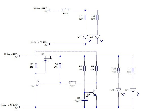
latch_zps7ec93a75.jpg


The first circuit is one with a latching switch SW1. The second is the same but with a regular non-latching push switch SW2. As you can see it's a fair bit simpler to just buy a latching switch :p

The industry often makes latching circuits with a regular switch rather than using a switch with a mechanical latch because for mass production it turns out the latching switch is more expensive to use, but for a single use, the difference will be tens of pence maybe.

Edit: Just noticed a small error on the second circuit. The trace from the top of R5 just crosses the 5V rail, but it should join it.
 
Whoa... that picture makes my squid brain go er.. squishy :p I think you are right, a bought latching switch is 100% the way forward! heh :p

Thanks for the help though man, really appreciate it&gives me a few ideas on how to best implement it once i get my case up and running. For now i think it is bagel time :D
 
Yeah :) No problem, feel free to PM me if you want to ask any questions about it :) Enjoy your bagel :)
 
Back
Top