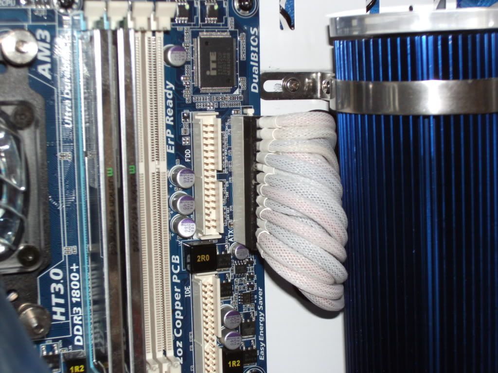
PSU Cable Sleeving

sushisky

New member
Hey guys, I'm really interested in individually sleeved cables, but I'm kinda confused about the whole ATX pin and locking flaps thing. Can anyone clarify for me? Because in many guides, they mention pressing it in and stuff

Aside from that, I'm also unsure as to whether or not you can sleeve the default cables

http://hardforum.com/showthread.php?t=1599965

This thread shows making new cables .-.

So do you sleeve existing cables? If so how do you remove the wires from the connector block? (Just pull)

Also, if it proves to be too much work, I wouldn't mind buying sleeved cables, from like corsair or nzxt. The corsair ones seem to paired to specific models though. Does anyone know if I'm going to be able use the replacement cables on my XFX P1-850B-BEFX ?

http://www.corsair.com/us/power-supply-units/psu-accessories-1.html
 
You can definitely sleeve existing cables. You just need a specific tool to be able to get the pins out of the connector. This is by far the best one that you can use for ATX pins (Ie the 24 pin, PCI-e pins etc):

http://en.mdpc-x.com/mdpc-sleeve/sl...e-tools/pin-remover-by-molex-the-original.htm

This is the best because the company that designed the pins in the first place also designed this. You can get cheaper ones but they tend to to be flimsy and break.

Basically on the side of your ATX pins, there are small tabs. These tabs are joined to the actual pin and are digging into the plastic of the connector on each side of the hole. When you use this tool, you stick it in there so the two pointy bits are horizontal, this depresses these tabs on the pin, which lets it slide out of the connector. It can be easier to push the wire in as you also push the tool in, to make sure that the tabs have not actually got stuck in the plastic.

It is a lot of work, a whole PSU could take you a good chunk of the day to finish.

An advantage to doing it yourself however is that you get to choose the style and your colour combinations. There are two styles to it:

With or without heatshrink (Found the picture on overclock.net) :

c2dbe14c_photo103.jpeg


As in that picture, you can choose the colour combinations. Many of the pre-sleeved cables you can buy are sleeved in just one colour, but if you do it yourself you can personalise it.
 
Much better is without heatsink, I mean that is only to hold sleeve.
It;s not important to look on that. That part is worse pain for me than remove pin from connectors. Because they never can be same.
And during bent after some tome start to look bad.
 
how do you sleeve double wires tho? :/

you can fit two wires into one sleeve run if absolutely necessary.

If you can do that, then I'd definitely recommend that route. However, it's
not always possible (I'm currently working on a sleeving job where I can't
do this because the wires are too thick). In that case you can either try to
do two fully sleeved separate wires leading into one connector and then use
a piece of heat shrink (or something else, I'm using nylon cord, see HELIOS
build log for more info) to hold it all together.

If you have enough space in the connector, you could possibly also do two
separately sleeved wires and melt them onto the connector, but I'm not sure
if that would work.

Or you can do something like this:


However, I'm not completely sure if I'd recommend this version in all circumstances.
Oftentimes, the second wire in a double wire is a so called sense wire, which
is used for the PSU's voltage control and regulation mechanism. If the end
point of that wire is no longer at the crimp, but instead somewhere back along
the wire carrying the current, you might get false voltage readings off that
sense wire and throw your PSU's voltage control off. I'm not sure how pronounced
this effect is though, and I haven't read about anyone having problems yet,
but then again I doubt anybody has done serious testing on this.
 
Last edited by a moderator:
why do the connections have double wires? (really confused about this)

I'm not an absolute PSU expert, so if anyone spots an error feel free to correct me.

Every PSU needs to do voltage control. This means that the PSU needs to check that its 12 V
line actually puts out 12 V, the 5 V delivers 5 V and so on. The important part is that those
voltages need to be supplied at the connector to the components, and not where the PSU
connects to its cables.

Now, there's a nice little equation linking resistance, current and voltage drop over an electrical
element:
Code:
U=R*I
U: voltage drop over element
R: element resistance
I: current through element

Every wire that goes from the PSU to each respective component (say, the 24 pin connector
on the M/B ) has a resistance and a current which flows through it (usually). That current can
of course change depending on how much load the system is under.

So the voltage drop between the PSU and the 24 pin connector on the mainboard will not always
be the same and will change with system load. Voltage regulation needs to take this into account.

In order to be able to do that, the PSU needs to measure the voltage at the M/B end of the
connection. In order to do that, you use a second wire which you connect to the M/B crimp
terminal on one end and to a voltage sensor input on the PSU side. That wire will have almost
not current
flowing through it, meaning that the voltage drop over that wire from the 24 pin back
to the PSU will be practically nothing (or, to use an engineer's favourite word: negligible ;)).

Example:
Let's assume you have an 18 AWG wire going from the PSU to the 24 pin, delivering a current
of 5 amperes. The voltage drop you will have from the PSU to the M/B in that wire will then
roughly be:
Code:
U=R*I=rho*L*I=0.00002096 ohm/mm * 500 mm * 5 A = 0.05 V = 50 mV
U = voltage drop over wire
rho: resistance per length of wire, 0.00639 ohm/foot
L: length of wire, 0.5 m in this example
I: current, 5 A here

Source for wire resistance value (I've metrified it for this calculation): link.

In this example you would have a voltage drop of 50 mV between the PSU and the 24 pin
on the M/B, which is not insignificant.

The secondary wire has no current flowing through it (or almost none, not 100 % sure on that,
somebody who's an expert on PSU design might be able to say), which means that the voltage
drop over the secondary wire from the 24 pin back to the PSU will of course be:
Code:
U=R*I=R*0=0

And this allows you to accurately read the actual voltage at the 24 pin connector. Of course I
have not taken into account the actual resistance in the crimp connector and all that stuff, but
I hope this makes things a bit clearer.

This is also why I'm not sure if there might be problems when you connect the voltage sense
wire to the current carrying wire almost back at the PSU. The voltage you will read with the
sense wire will be incorrect in that case. Whether or not the error will be large enough to cause
any problems I'm not sure about.
 
They have double wires sometimes because the connectors sometimes have less pins. eg, power supply cale for graphics has 6 pin connector for gpu end and 8 pin at the psu end.

Power Supply cables are coloured for a reason and that so we can identify the voltage of the cable as each colour has it's own voltage.
It's just the industry standard which can be confusing but with a little reading becomes apparent.

To braid a split cable the best way is to use 3 pieces of braid, 1 for each straight line of the Y section with a heatshrinked joint which will be hidden behind the motherboard tray after if that makes sense.

What i found easier when starting out was to sticky label each wire numbering them 1-24 and then draw a diagram of the connector so you know which wire goes where when reassembling.
 
Last edited:
so since the second wire is for voltage reading and regulation, it would be bad to cut it off or recrimp it?

I'd say cutting it off completely is probably a pretty bad idea since you would
take away the PSU's capability to control and regulate the voltage coupled to
that wire. I would not be surprised if you'd actually break something with that
(example: cutting off the + 12 V sense wire will lead to the PSU getting a
measurement of 0 V on the + 12 V line, which might lead to some very bad
voltage regulation reaction).

Lutro0's version of simply branching the wire out somewhere at the back I'm
not completely sure about. Voltage measurement will be somewhat compromised
but since you can adjust your voltages in the BIOS (usually) you could actually
compensate for that to some degree. The voltages measured by the PSU would
be slightly too high (the actual voltages at the connector would be somewhat
lower than the PSU believes them to be), so you're not going to accidentally fry
your components or anything, it's just not exactly what I'd call an optimal solution
from an electrical point of view, and if your setup is sensitive to bad voltage
regulation (say, if you're running some significant overclocks) then this might
lead to failure sooner than a proper two wire cable.

The most elegant solution I'd say is to run two separate wires for the full length of
the cable inside one sleeve and then branching out of the sleeve somewhere
close to the PSU. If that's not possible, then I'd personally run two separate wires
with separate sleeves, but if you want you could try Lutro0's version, I have not
yet heard about anything horrible happen due to that, it's just not something
I'd personally do to one of my own rigs.
 
For 24pin motherboard connector google power supply unit computer and hit up the wiki page, you can find a full pin out with voltages and colour guides there.
Very very useful.
So long as you remember where each cable goes the braiding itself is very easy but also very time consuming.
If you can get away without cutting wires all the better but if you have to, just take your time and think about how you want your end result to look, draw diagrams if nessecary, and label the cables as suggested before.

Another thing to keep in mind is that psu's store energy so be careful when opening your psu up, some can hold charge for days after being unplugged and i for one wouldn't like a zap off one.
Nice to see someone having a go though so kudos for that.
 
Last edited:
wow. is it possible to have a psu with cables that are all single wire? or will there always be some mixed in :/

I don't see how you could do a (good) PSU with only single wires since then you'd
have to implement another control mechanism for voltage regulation, and I can't
think of a way to do that without the sense wires.

Best you can hope for is that the pinout on the PSU side is reasonable enough so
that you don't have a lot of tangled and crossing wires, but I don't know of any
PSU that's really perfect in that regard at the moment.
 
Back
Top