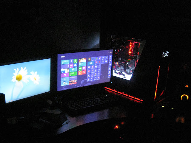
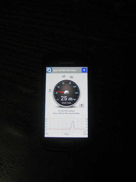
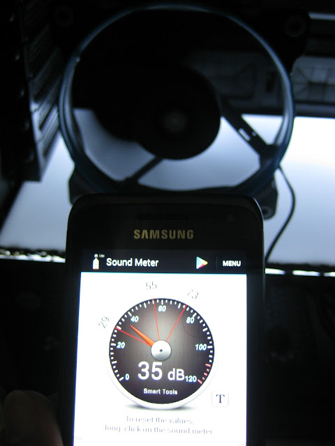
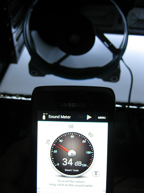
Doing some tests to find the prefect fans for my needs. This is the ambient sound noise at night...
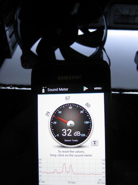
Gentle typhoon at full speed:
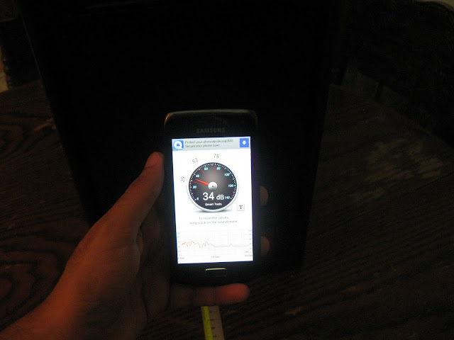
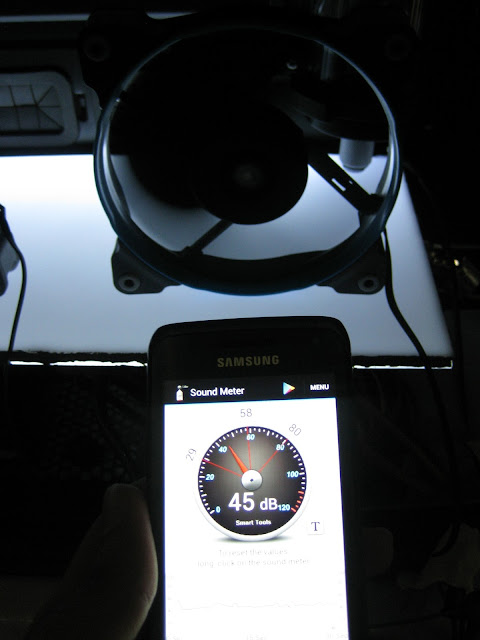
Ambient sound noise during corsair sp120 tests (done in the daytime):
SP120 Quiet Edition at full speed (12v):
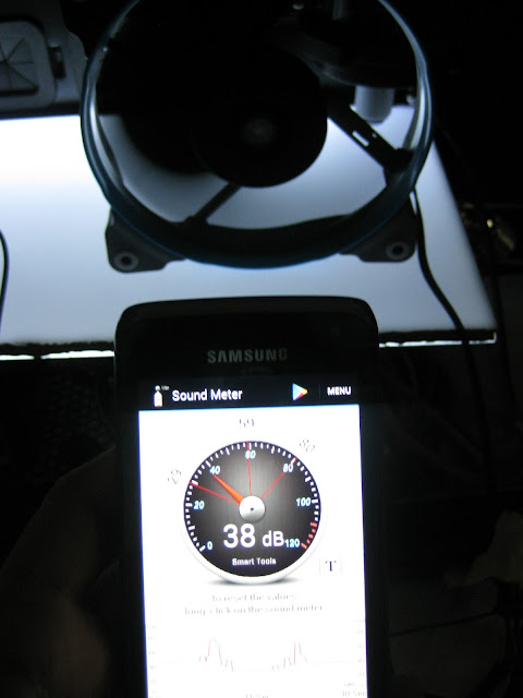
SP120 Quiet Edition (7v - using the included adapter):
SP120 High Performance at full speed (12v):
SP120 High Performance (7v - using the included adapter):
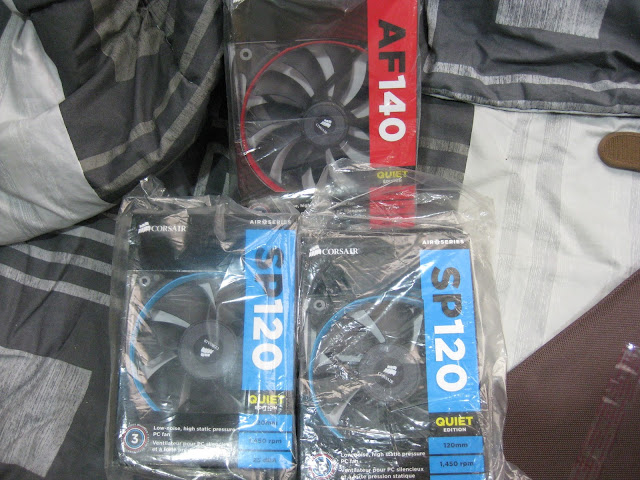
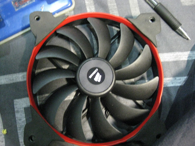
All this tests are not accurate & do not serve as a guide or comparison on which fans are noisy/silent. Its purely for my own usage, to finding the fans that will suit me well. I decided to use the corsair SP120 quiet edition in my build since I am going with a push + pull setup. Gentle typhoon is a good fan no doubt but its not pleasant to my eyes
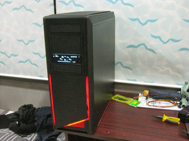
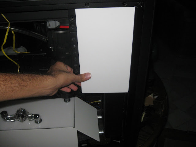
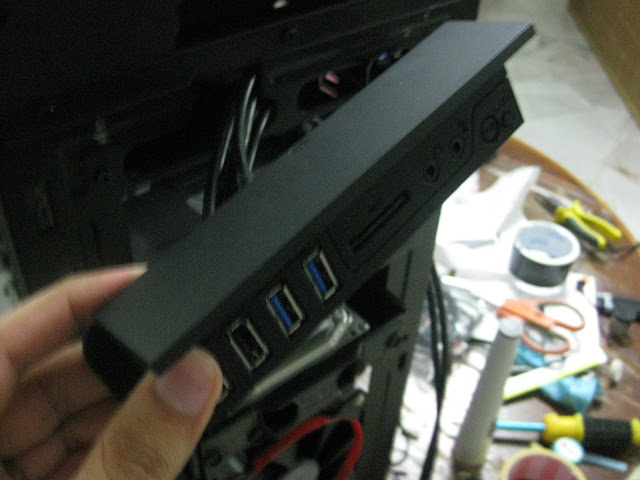
Oh and I also got my top panel replacement from nzxt already

Tiny update:
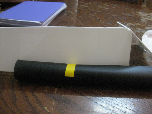
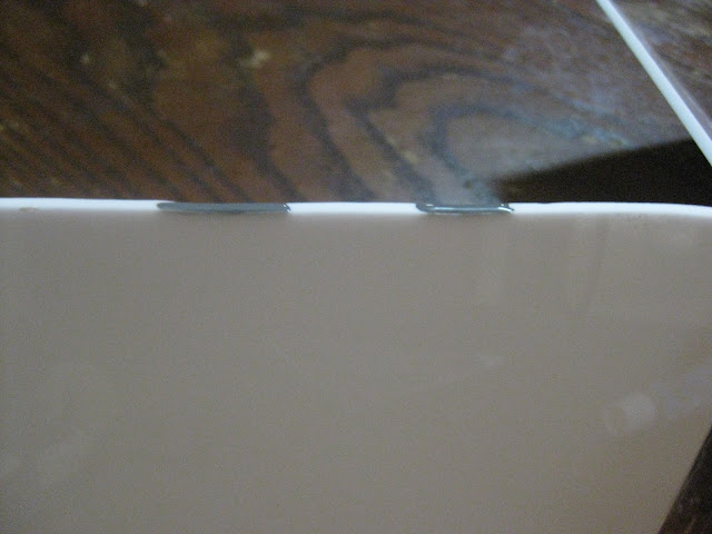
Before you guys say anything, I would like to remind you that I already mention before I start this worklog that this will be a very slow build which explains why there isnt much yet. So I just finished installing the gaskets in my rig, I am the very paranoid type of person when it comes to sound. I am planning to go for the ultra silent rig yet performs well in cooling which explains why I keep changing fans from SGT to SP120 high performance to quiet editions and its pretty obvious why I am installing gaskets all over the places haha. Anywhere there is fans contacts, there will be gasket! Also my supplier only had the 360mm size so I had to cut it to fit at the front radiator.

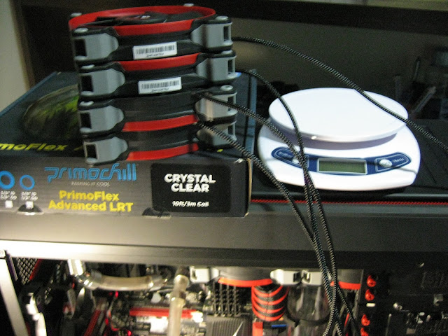
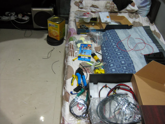
Flowsensor is here! I had to make a special order for this since cant get it locally!

And some 'rare' fitting sizes & g1/4 rotary's since local retailer only carry 1 size

Best part of unpacking is to find suprised goodies! Its not that it very expensive or what but its just the surprise that you get free stuff makes the whole experience happier. The packaging is superb too, wrapped in bitspower own bubble wrap!
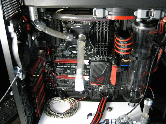
I know its been sometime since the last update & I apologize for that. Was busy so had to put the work log on hold. Don't worry though, I am free now for a month or so. You will be seeing more updates now. I just finished installing the gpu waterblock, ek bridge & the backplate (I forgot to take picture of the final product). Anyways I plan to start making fill ports tomorrow on the luminous panel.


Almost forgotten to remove the original asus washer haha, luckily I realized it otherwise it might not have good contacts with the waterblock :lol:
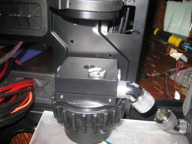
As promised, more updates today") Had to draw circles for making hole to fit the fill port.
Had to draw circles for making hole to fit the fill port.
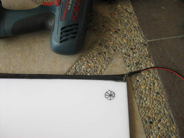
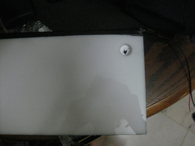
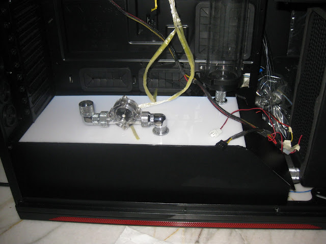
It worked out great, perfectly aligned but I have a new problem.
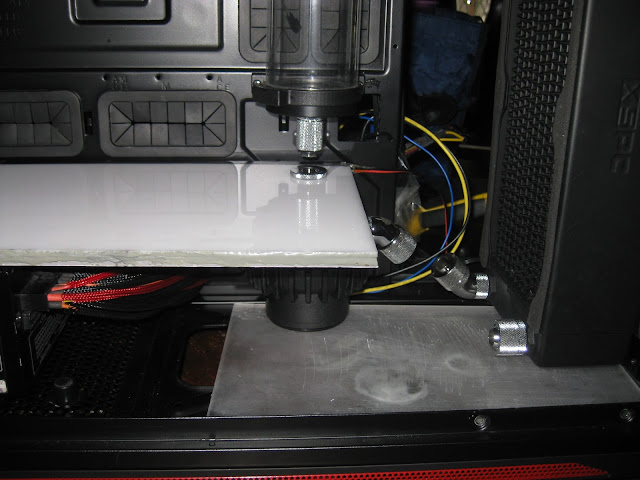
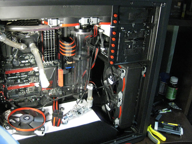
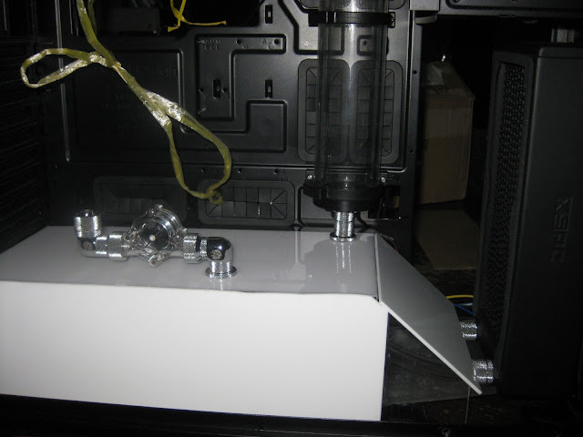
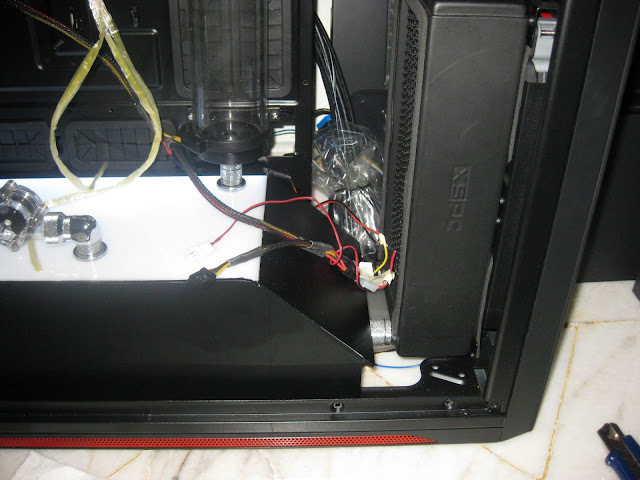
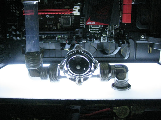
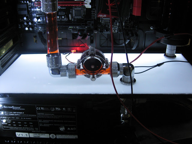
So my main objective was to get the pump directly under the reservoir but its super tight. As you can see there is no gap at all between the pump top & the luminous panel.
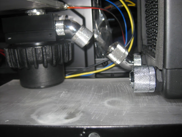
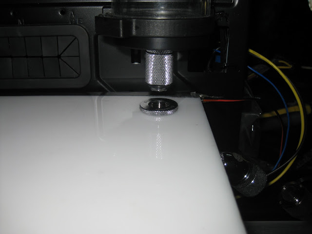
Another problem was the pump inlet fitting & the fillport is not aligned. The pump is a little too thick so it offsets outwards a little bit. And also the 45deg rotary isnt straight. I can solve it by rising the pump higher but I dont have space though to rise the pump so had to use 20mm extender at the radiator

As for the pump offset problem, I had to use a dremel to grind the pump cover or whatever you call that round circle thing that secures the pump top & the pump. Basically I trim the gripping material a little bit so that the pump can enter inwards a little more. Sorry for not taking a lot of pictures, when it comes to modding, taking pictures is my less priority since I spend too much time doing the actual work
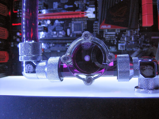
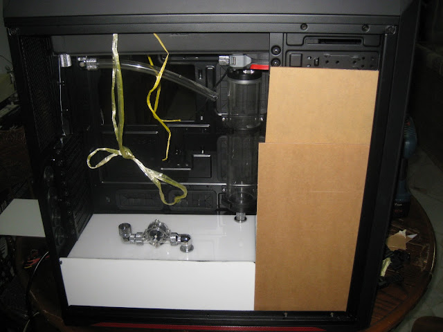
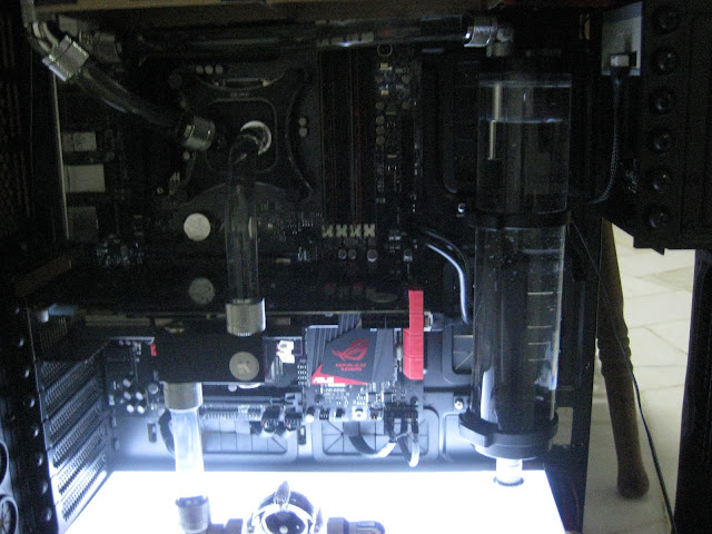
Made the 2nd fillport yay! My initial plan was to put this flowsensor at the reservoir inlet at the top & use extenders from the fillport to the bottom of the gpu inlet. So that I can run a straight tubing from the bottom to the gpu inlet. This will give the straight tubing that we usually see in acrylic tubing builds but then I thought why not replace the extenders with my flowsensor? Plus it will be easier to see on the luminous panel instead of the top & also save me from using extenders therefore less cost! That long extenders is just for aligning, will replace that with compression fitting & tubing.
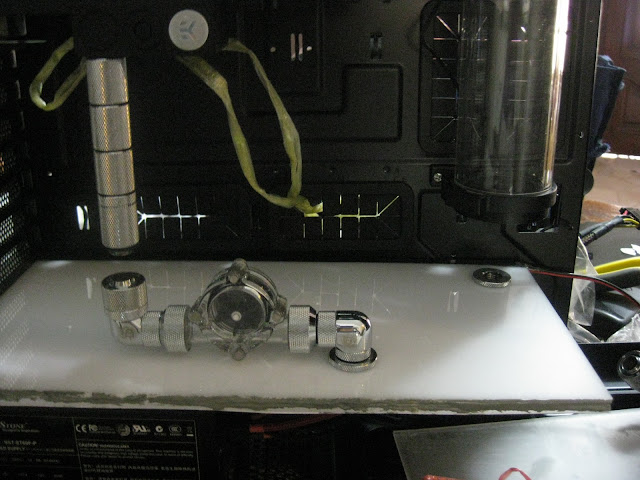
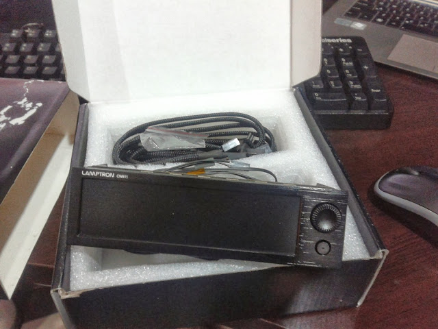
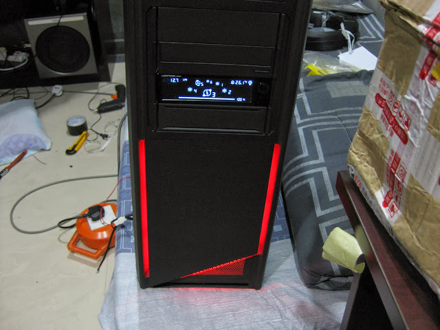
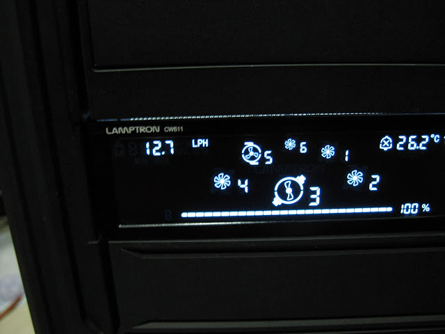
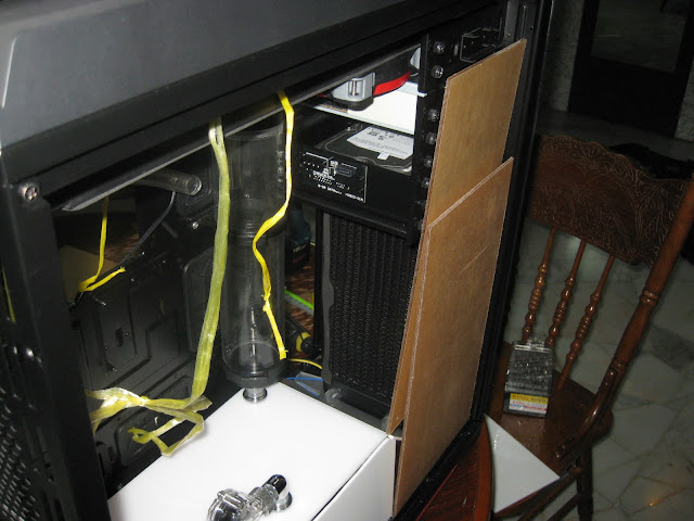
I tell you, this is probably the hardest part in my build so far! First I need to attach the pump to the fillport at such a tight space, then from the fillport I need to connect to the reservoir at such a tight space to work with. Once everything is set, I had to connect this small piece of tubing to the radiator & oh boy...it was so hard! Because I cant move the pump or have enough space to work with. Took me more than 1 hour to get the lower portion done. I had to remove to rivets at the back of the casing to fit this luminous panel properly below the pci bracket & I also drilled 2 big holes at the bottom acrylic panel to route the pump wire from below the casing & also allow me to adjust the pump speed. Not convenient to adjust the speed from under the casing but at least I have the option if needed. I plan to connect this pump on a lamptron cw611 though so it will allow me to adjust the speed through the fan controller instead.
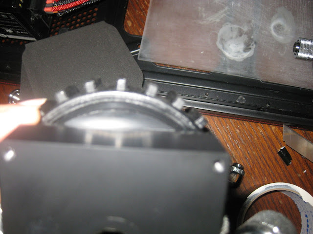
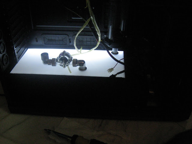
This is what you get when you dont have motherboard. Had to hang the gpu with strings to get the accurate measurement for the fillport locations.
So far everything is looking good, will work on the psu side cover & at the front. Took me more than half a day to get the lower portion routing done. It looks simple but I did a lot of small modding here & there to get it in such a tight space.

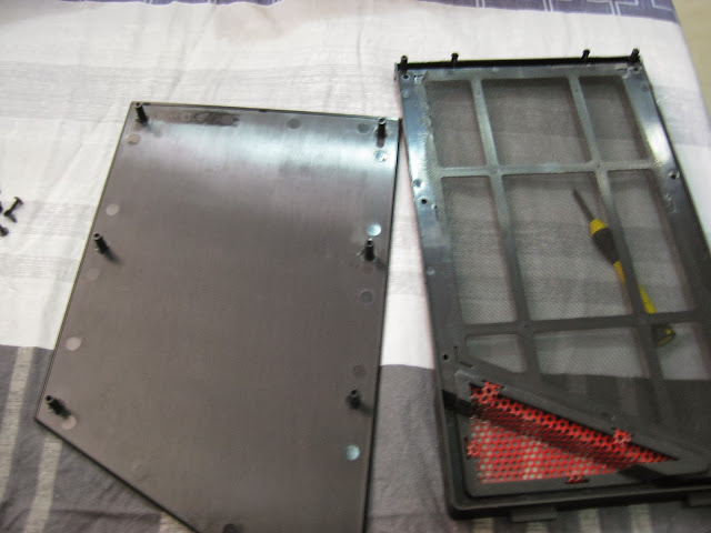
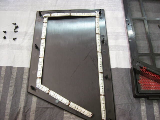
The luminous panel is just a prototype though, but I dont plan to change it since is amount of work I need to remove the fittings & put it back is such a pain. If the led 1 day failed then only I will decide to create a new luminous panel with laser engraved instead of hand sanded for better light distribution. I also have an idea to make a aluminum bracket to fit the led inside whenever it fails, this will make the whole replacing led process easier. Basically what I mean is instead of using black tape to hold the led strip to the side of the acrylic, I will create a thin spacing with aluminum instead.
Not sure if you understand what I am trying to say but for now I think I will just use the current luminous panel.
Thanks to [@pristine] for borrowing me his hole saw Making fillport will be super hard without it! But the hole saw is a little small for the bitspower diameter so I had to use grinding stone to sand the hole further so that the fillport can fit inside nicely. I know the holesaw was designed like that because when you make hole with metal, you can use the fill port threads to screw the fillport in but not with thick acrylic panels
pristine, I will return it back to you soon
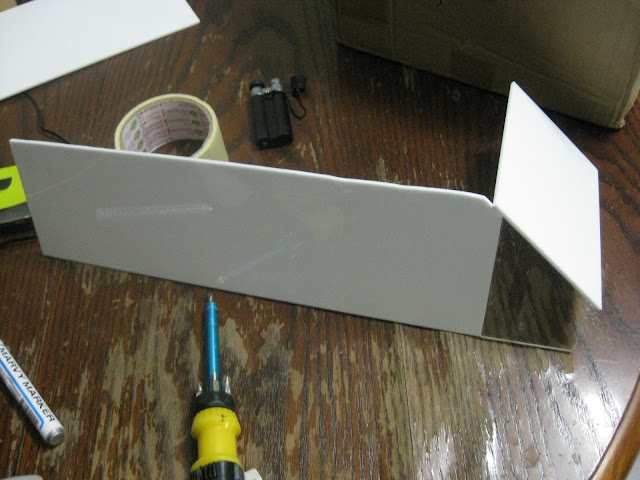
The side cover is a little high so I will need to trim it a little bit.
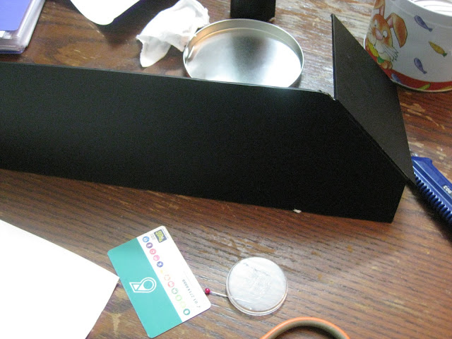
My design is to put another acrylic at this angle to help the airflow from the radiator.
Due to short acrylic panel, I had to glue another acrylic to it I am going to cover it with matte black sticker so the colour dosen't matter. Most importantly is to make good use of the resources you have! Don't waste it
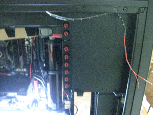
Done with the whole cover but I had to make a hole & attach a screw to keep the acrylic panel touching the luminous panel otherwise there will be a gap
Easy to remove too, so cable management from the psu shouldn't be a problem. Just pop it out & plug in hehehe
I know the side panel is not straight but this is probably the best I can do with a dremel. Once I put the sticker I think it wont be noticeable.
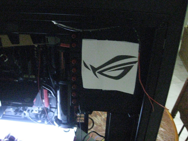
Now I need your suggestion, should I cover this part like below? Full cover or partial?
If I cover it fully then the 5.25" drive bay part also I will need to cover...
Or should I just cover the top part, meaning the radiator & sp120 fans will be visible. I plan to make an ROG logo ...still thinking which to go for since full acrylic cover is very common & everyone done that already. I am thinking of doing something different.
Got my vinyl from [@kray_keigo] today. Serious good high quality stuff :thumbs:
As you can see from the picture, my previous cut with the dremel wasn't that perfect. Shaky hands so a quick fix with eproxy & you won't even notice it hehehe
My touch & go card definitely helped me in applying the sticker without bubbles
I am quite satisfied with the psu cover considering this was my first attempt, not so satisfied with the luminous panel yet as you all know but since this isn't a sponsored build or what sort, just my personal rig so who gives a fark I can perfect the luminous panel but that would mean me taking apart the panel, unscrewing lots of fittings here & there that took me quite some time to get it in place with such a low clearance plus I might need to spend probably another RM50-100 to get the material, laser cutting etc so I think i'll pass.
In case if there is a leak during the leak test somewhere under the psu cover & I couldn't fix it without taking apart then I might consider getting the luminous panel perfected. Lets just hope no leaks ya
Still deciding to go with 5.25" bay cover with acrylic + matte black sticker or acrylic + ROG logo. Once the side panel is on, there won't be any difference so I am still thinking on my options
It's either bending the metal or cutting it off with a dremel. Went with the lazy method lol otherwise the acrylic panel wont be able to sit nicely over here.
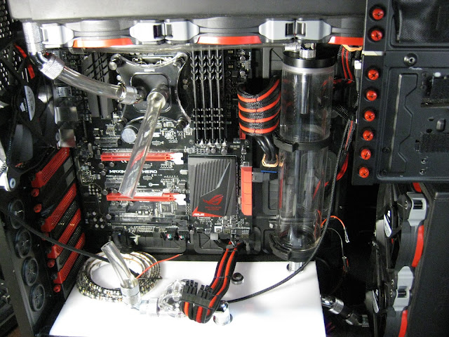
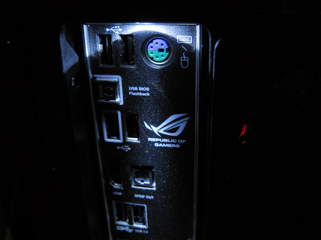
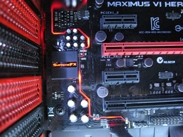
Hero & haswell is here, yeah I went for hero finally. Dont intend to wait for formula any longer plus I got hero from a friend at an attractive price
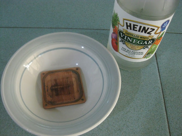
So I did the usual process, install cpu, mobo standoff etc..before putting on the waterblock with thermal paste I decided to open it to take a look inside & what a horror!!! Oxidation so badly, this is basically my fault though. I run the loop for 2days & drained it for some changes but didnt let the components to dry properly & just left it there to dry itself haha. Also if you notice the o-ring somehow left those black marks on the copper & it was hard to remove it even with vinegar. Not exactly sure what is going on but I hope it dosen't leak. o-ring condition is still good though...
The usual vinegar + warm water + lime solution
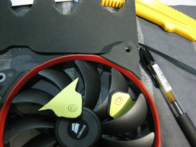
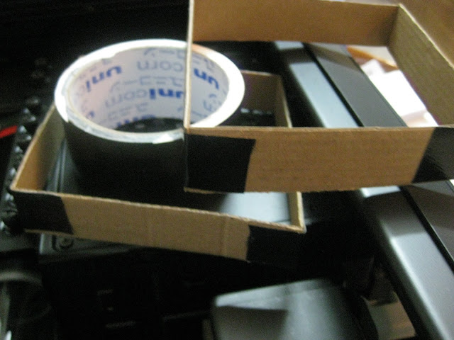
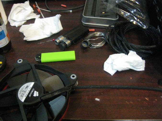
So since I am doing push + pull config, available space is quite tight considering I am using RX radiators. To make sure I have sufficient spacing, I made myself 120mm fan body to estimate the distance when installing my loop. This is because I dont have any 120mm fans spare & the sp120 fans I ordered will arrive in 3weeks time :lol:
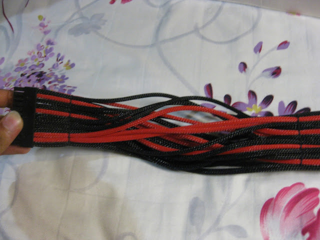
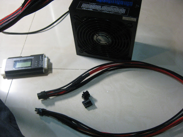
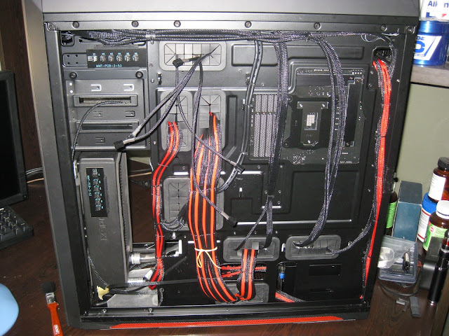
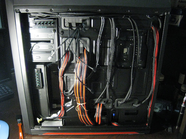
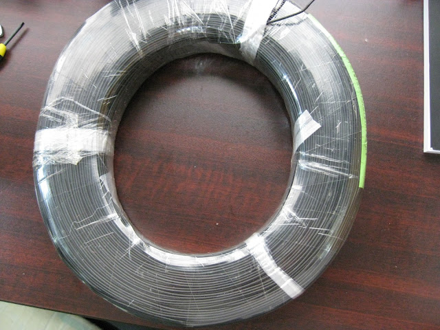
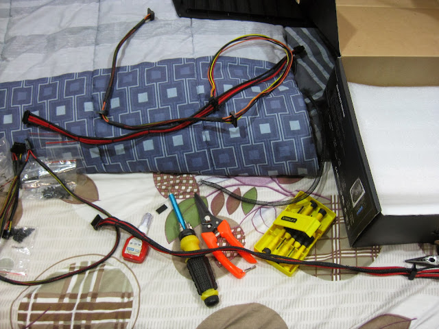
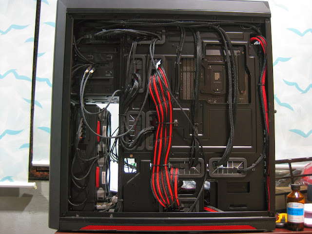
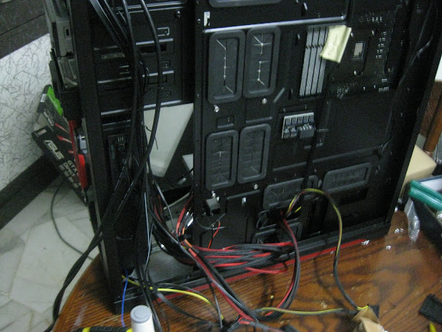
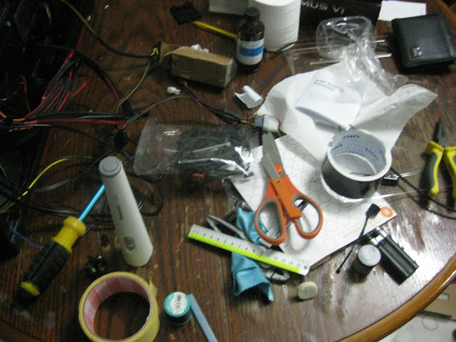
Started with cable sleeving, just the internal I/O cables only though, psu cables haven't yet and oh boy it was time consuming alright. Took me more than 2hours to get it done. Hard since I had to sleeving while standing & the cables are quite thick & of different sizes.
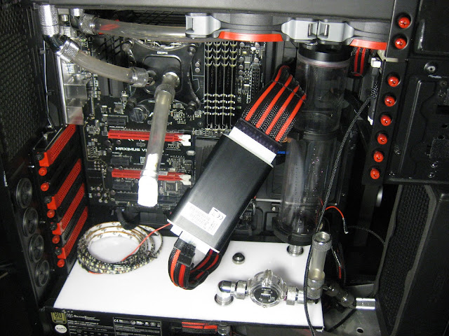
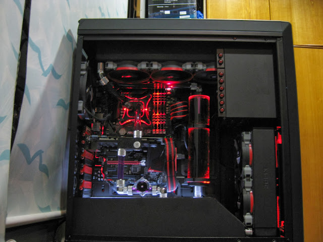
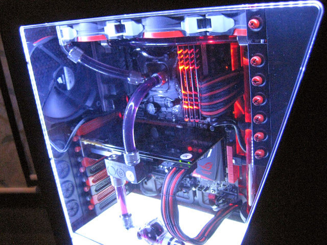
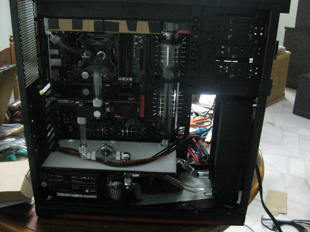
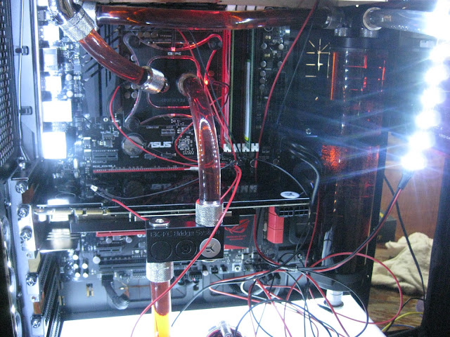
Current loop, short, simple & clean
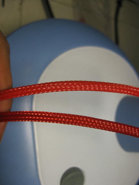
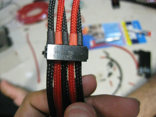
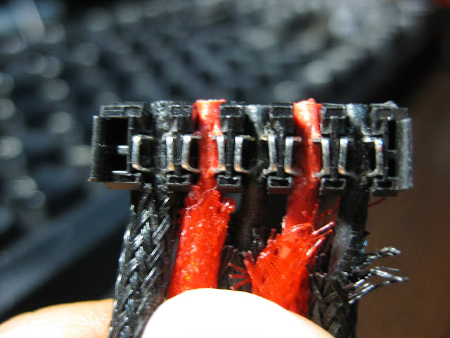
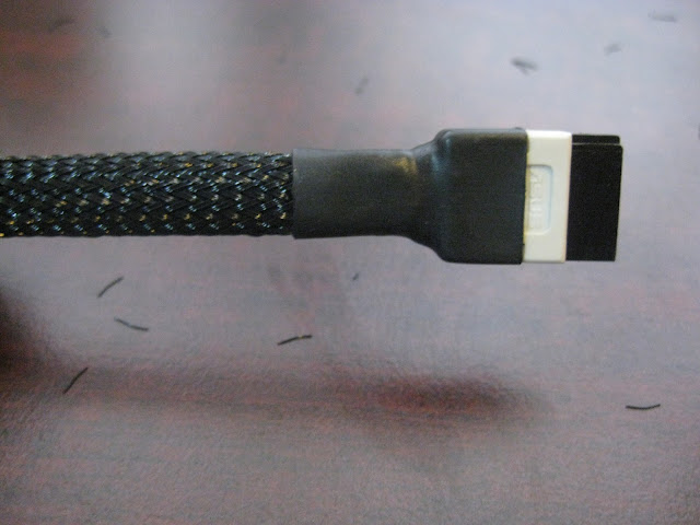
I sleeved using MDPC sleeving & I find it way better than colortrail sleeving in quality wise. Colortrail is quite good too & most importantly cheap but MDPC is much easier to sleeve but too expensive lol. I almost used up all my sata sleevings already for the internal I/O cables such as usb cables, etc. Need to get more for the sata cables. I am a little OCD on stuff like these, I know you dont really need to sleeve it but thats just how I roll. Maybe I am a perfectionist?

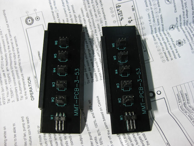
ModMyToys pcb installed!

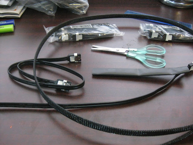
So yesterday I was sleeving the switch 810 front I/O cables & I used up most of the sata sleeving which was meant only for the sata cable. Sadly its enough to sleeve 1 sata cable only so now I got to order more.
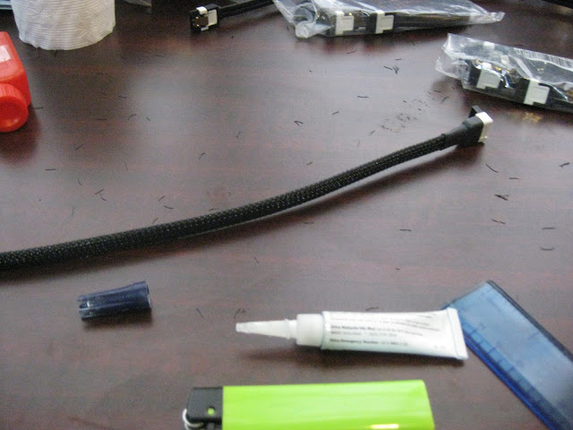
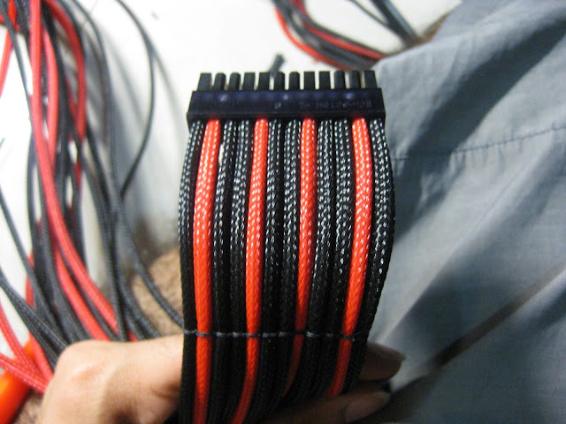
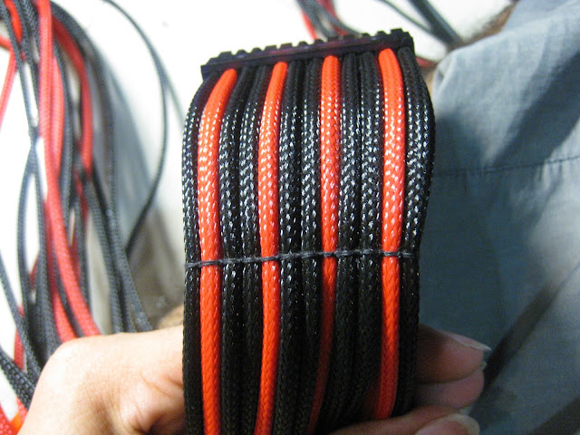
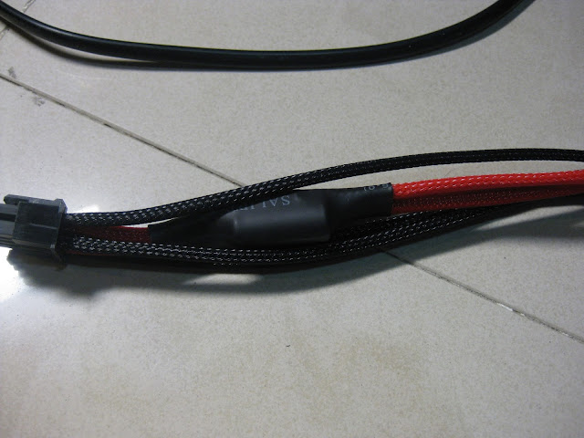
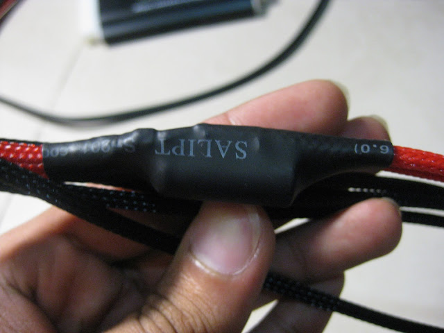
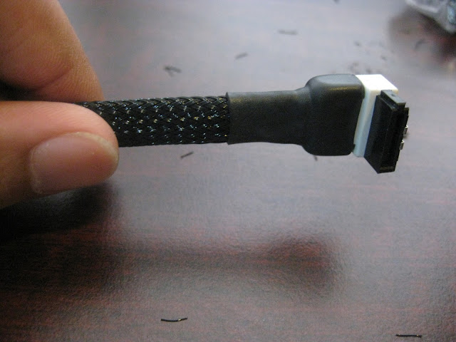
I am using MDPC sleeving btw and the quality is top notch. Applied a little super glue to the sleeving & cable so that it will not come out no matter how hard I pull it. I had bad experience with previous sleeving I did on 24pin cables so this time I will be adding super glue to give that stronger hold.
Time to start filling up the loop.
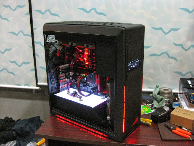
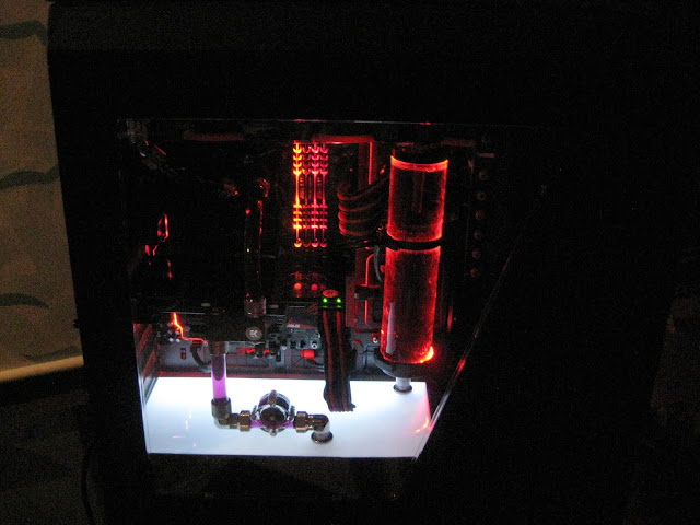
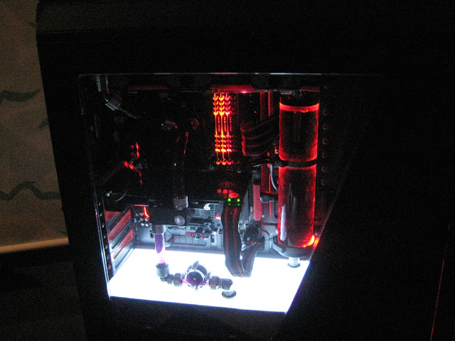
I plan to go for blood red colour to match the ROG theme.
Just experimenting with how much dye I need.

I only added 1 drop red & 1 drop blue but the liquid turned straight away to dark purple. This means the red ratio must be more than blue.
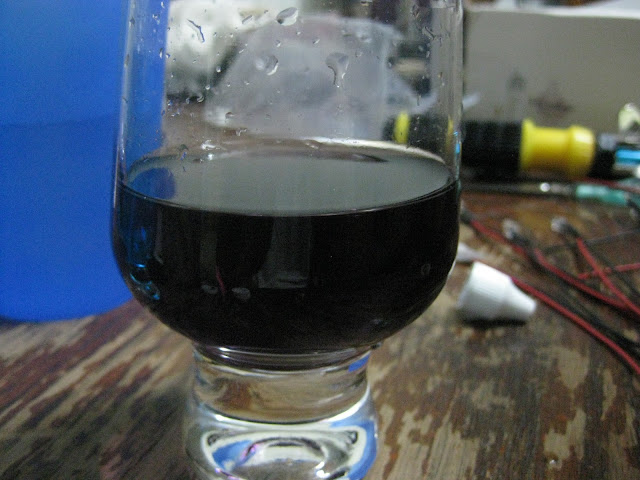
Sadly I was too confident & added lots of red & 1-3 drops of blue straight away into the loop. It straight away turned to purple. Now I got to drain the whole liquid & flush it with distilled water & get the ratio right. Learned my lesson lol, then I mixed the dye in a seprate 1.5 bottle first & started filling the loop from the bottle.
I got the colour that I need, the ratio I used was around 20drops of red & half a drop of blue. I drop the blue into a small glass of distilled water & slowly fill the water into the 20drops of red water. Used around half a glass so approximately only half a drop of blue is required.

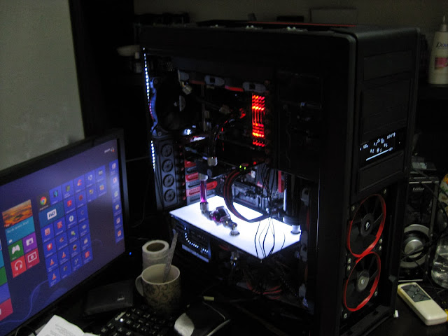
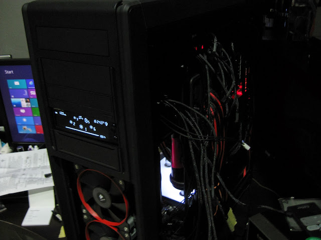
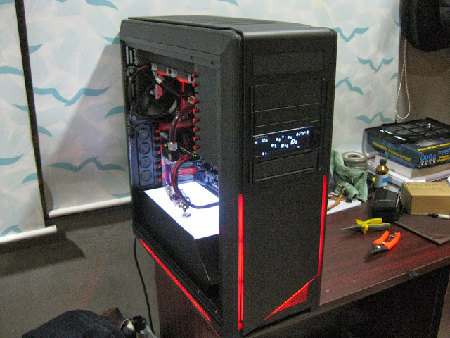
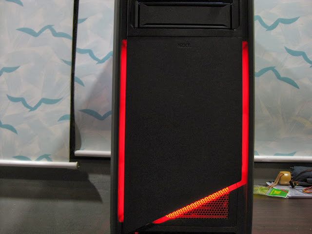
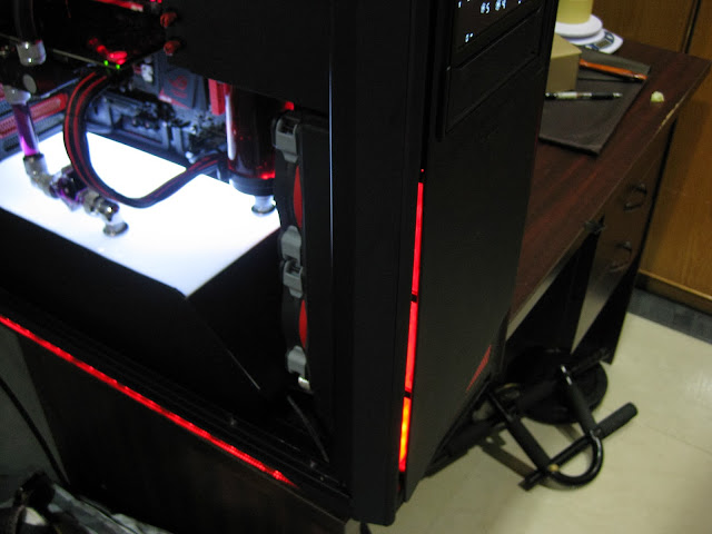
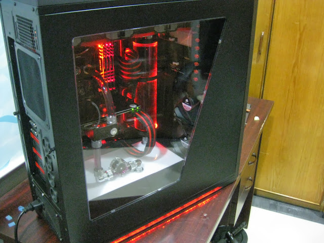
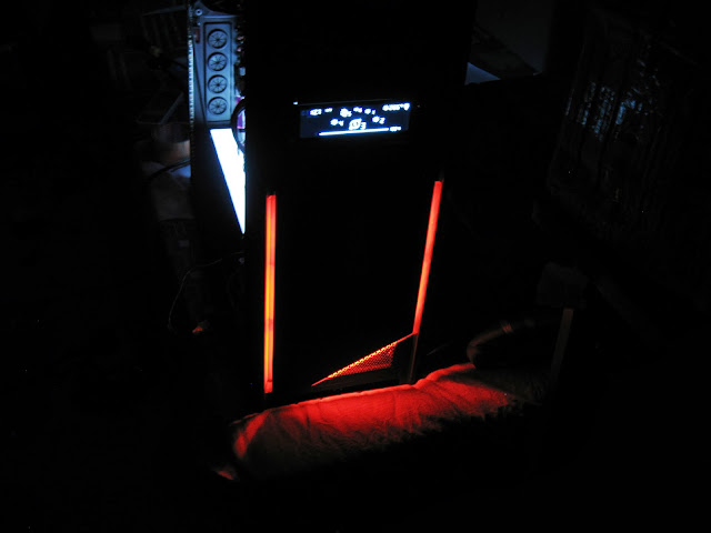
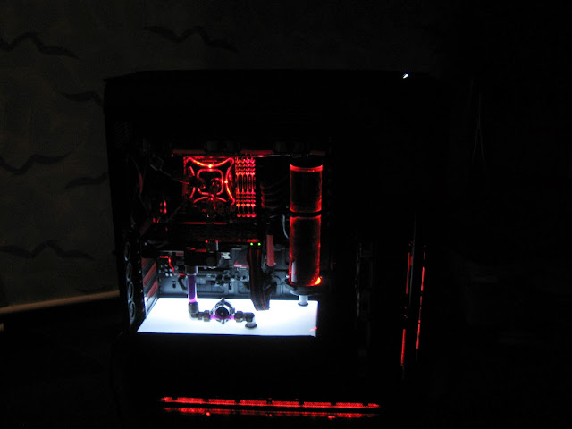
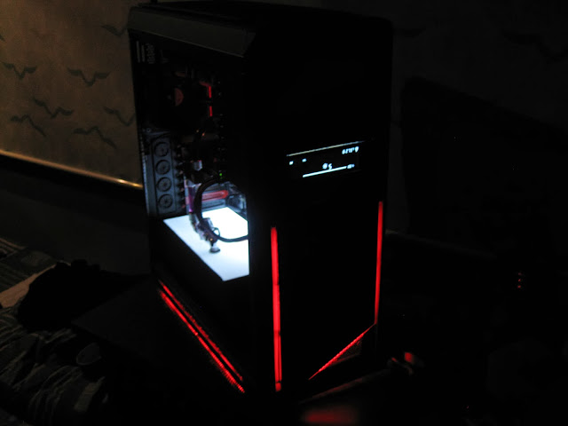
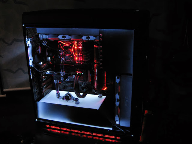
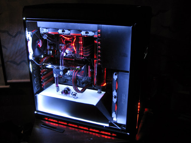
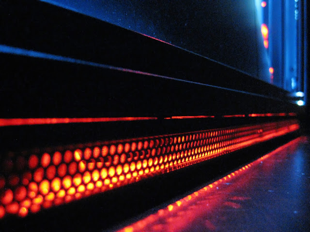
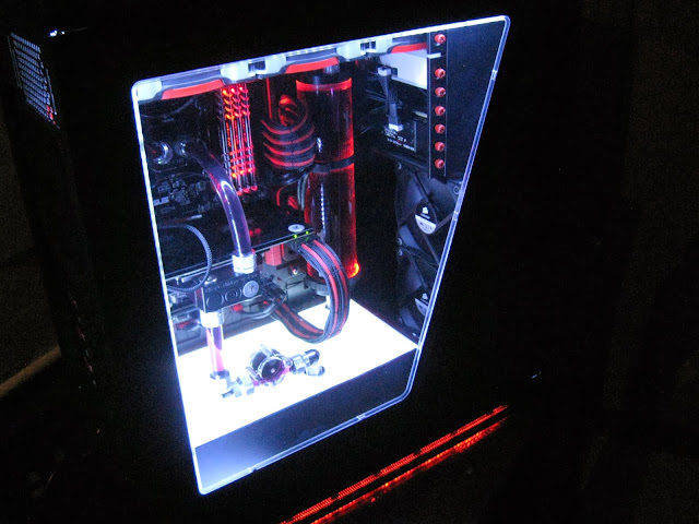
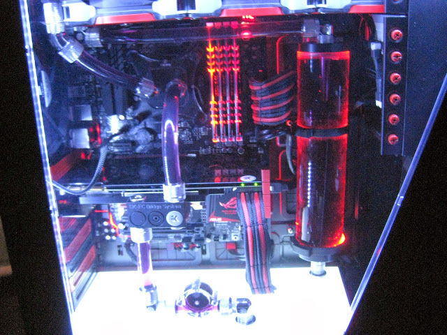
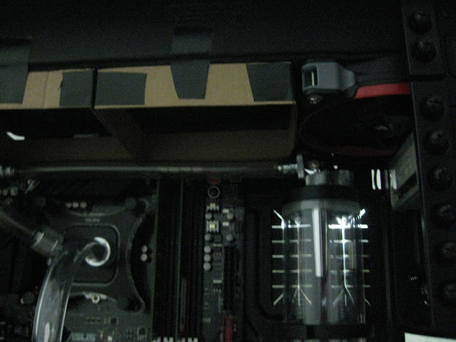
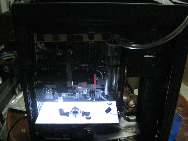
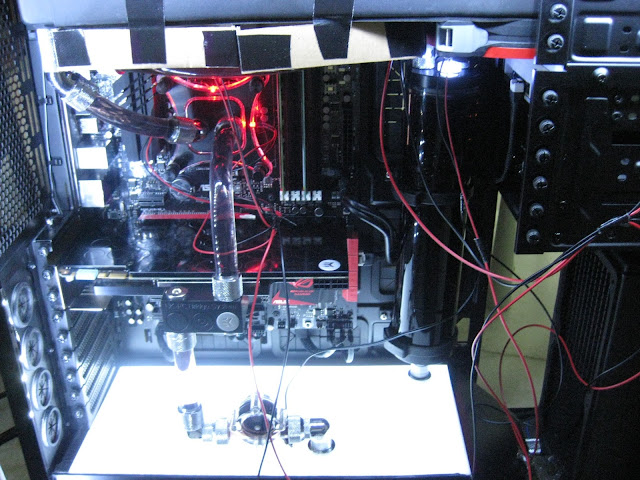
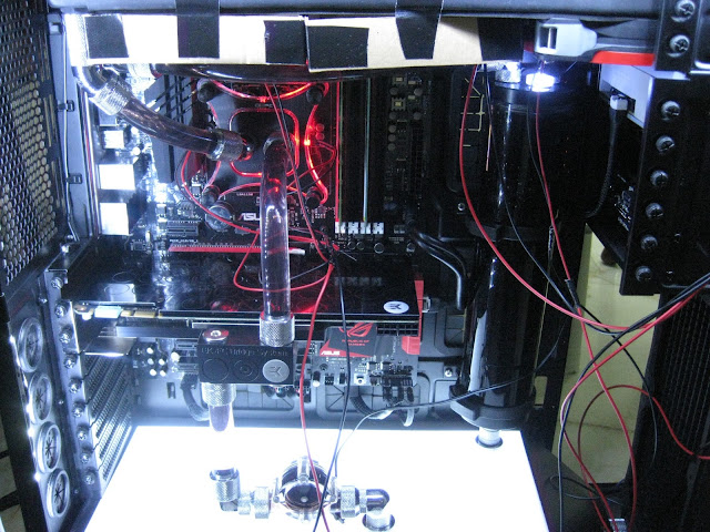
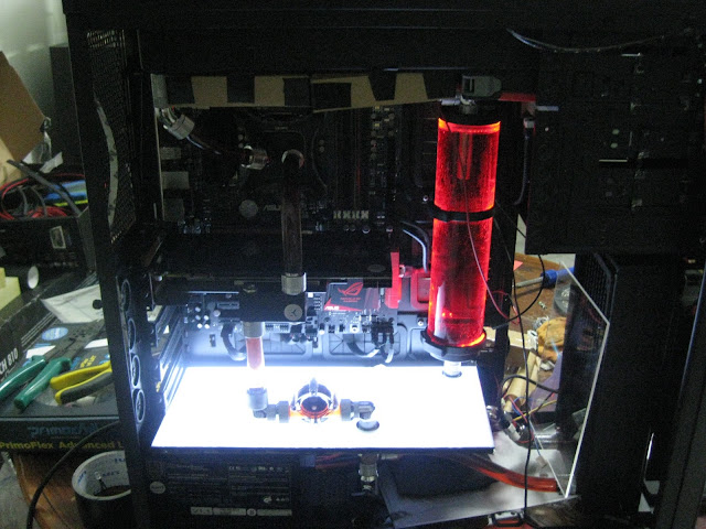
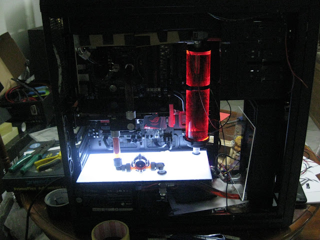
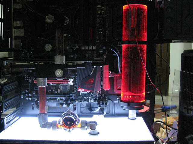
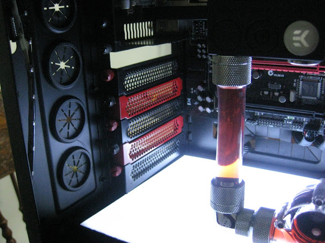
Upper part red looks fantastic but the luminous panel kinda make the red looks yellow/orange at the bottom part.
Ignore the cable mess, I am playing around with leds. Apperantly the 3mm & 5mm leds I bought was wrong, they are not giving constant light. The led is have the "pulse effect" blinks & dims, blinks & dims etc. This may be nice for some people but I dont really like it so I got to find the correct ones now haha.
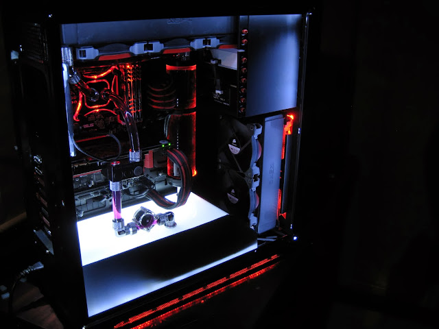
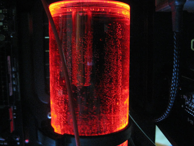
So do you like my reservoir? I hope the tiny bubble stays hahaha it gives a really nice effect to it, but unfortunately there are few scratches on the res. Oh well, people are not going to stare at it too long anyways right?

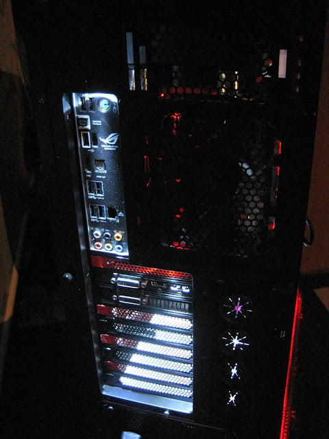
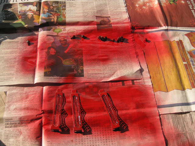
I did some red touch up today, just to highlight more red colour in my build since its pretty dark atm. Sanding the pci bracket is a pain in the ass I tell you, wished I had some paint stripper lol.

Here is the optical bay cover. Its a temporary cover I think. I haven't decide yet should I make a big ass ROG logo at here or just mount ssd over here. Oh & yeah, I painted some screws hehe, looks nice isn't it...
Initially I was thinking to make a luminous panel to display the ROG logo in white + red like how kier did with his build, but then I am thinking if I were to get SSD then where should I mount it. You know you gotta "show off" if you are using SSD right. So I am still deciding. Sorry for this blurry picture, lazy to adjust the camera ISO haha
Also kustom pcs is out of lamptron CW611. Noooooo!! Gotta wait for them to restock D:<
Didnt had any progress last week because my father accident 2weeks ago so I was staying up night in the hospital. Another bad news is that the rig is partially done, so I been playing games on it. Finished far cry 3 on it but today when I was listening songs the display suddently just went off. Now there isnt any display from the graphic card. I think my graphic card died so will need to test it & most likely send to RMA. This is farked up :lol:
I am almost done with it, just left to install the remaining fans & make custom cables but shit happens. I was hoping to finish this build by end of this month but...
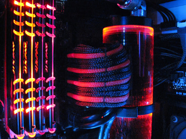
Anyways thanks to [@HoNeYdEwBoY] for the rams :wub: I didnt know the ram led has a pulse effect. I thought it was just a normal constant led (didnt read reviews :lol: ). Remember previously I had 3mm led for the raystorm & I didnt like the blinking effect, but since the ram has a nice pulse effect to it, I think maybe adding that blinking led to raystorm might match. Will test it & see how it goes

Sleeving the 3mm leds.

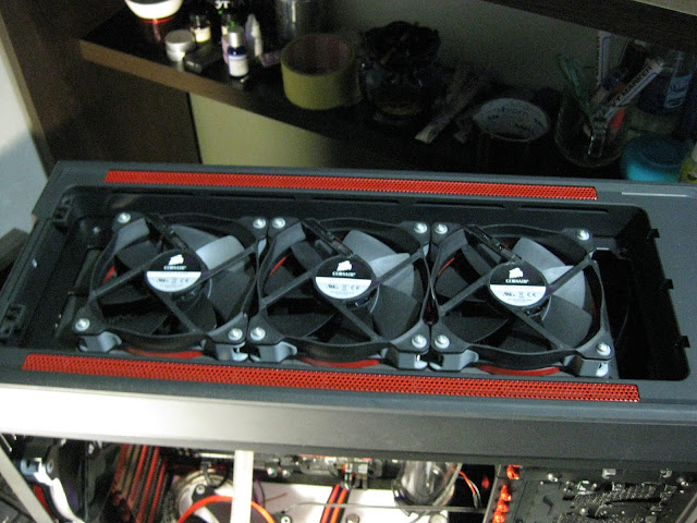
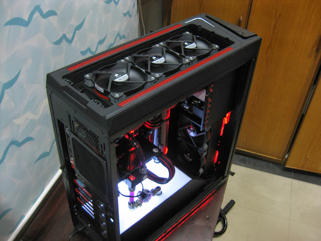
So I started adding fans on top & the standard 3cm radiator screws doesnt fit so I had to custom make my own screws that is slightly longer.


Started sleeving the fans too. Yes I am a perfectionist I guess, even fan cables I will sleeve even though its already black. Usually small touches like this can make a difference in a build.
Gentle typhoon at full speed:
Ambient sound noise during corsair sp120 tests (done in the daytime):
SP120 Quiet Edition at full speed (12v):
SP120 Quiet Edition (7v - using the included adapter):
SP120 High Performance at full speed (12v):
SP120 High Performance (7v - using the included adapter):
All this tests are not accurate & do not serve as a guide or comparison on which fans are noisy/silent. Its purely for my own usage, to finding the fans that will suit me well. I decided to use the corsair SP120 quiet edition in my build since I am going with a push + pull setup. Gentle typhoon is a good fan no doubt but its not pleasant to my eyes
Oh and I also got my top panel replacement from nzxt already
Tiny update:
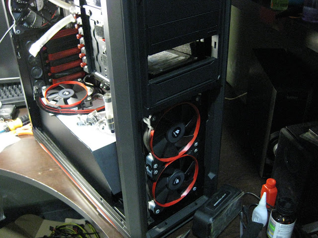
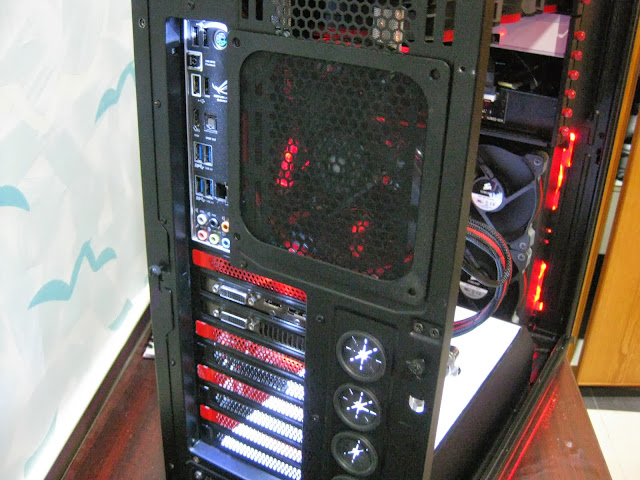
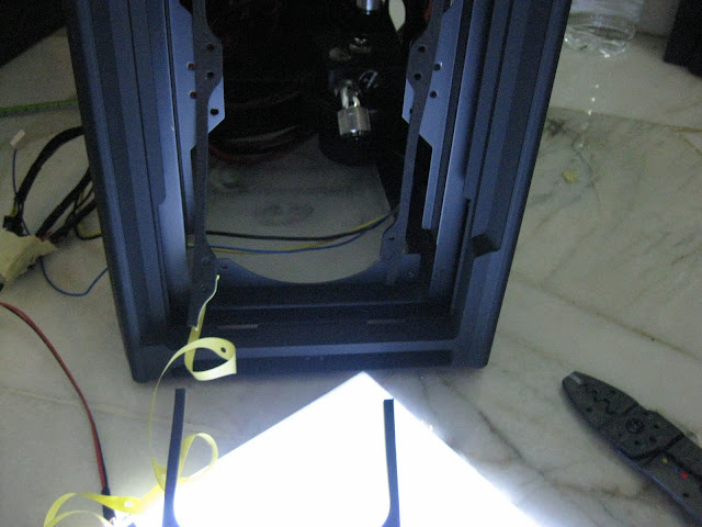
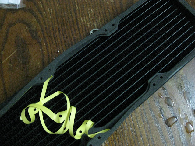
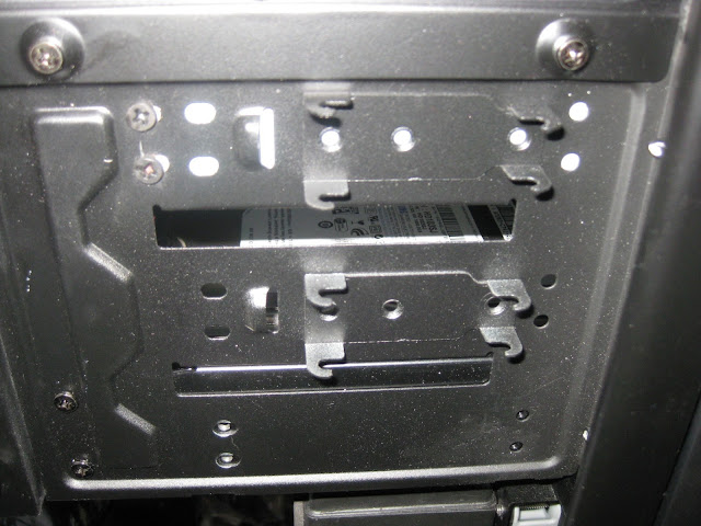
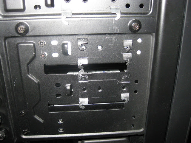
Before you guys say anything, I would like to remind you that I already mention before I start this worklog that this will be a very slow build which explains why there isnt much yet. So I just finished installing the gaskets in my rig, I am the very paranoid type of person when it comes to sound. I am planning to go for the ultra silent rig yet performs well in cooling which explains why I keep changing fans from SGT to SP120 high performance to quiet editions and its pretty obvious why I am installing gaskets all over the places haha. Anywhere there is fans contacts, there will be gasket! Also my supplier only had the 360mm size so I had to cut it to fit at the front radiator.
Flowsensor is here! I had to make a special order for this since cant get it locally!
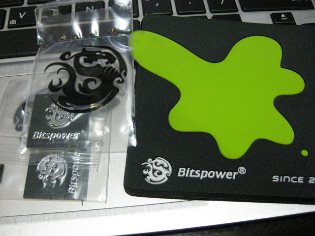
And some 'rare' fitting sizes & g1/4 rotary's since local retailer only carry 1 size
Best part of unpacking is to find suprised goodies! Its not that it very expensive or what but its just the surprise that you get free stuff makes the whole experience happier. The packaging is superb too, wrapped in bitspower own bubble wrap!
I know its been sometime since the last update & I apologize for that. Was busy so had to put the work log on hold. Don't worry though, I am free now for a month or so. You will be seeing more updates now. I just finished installing the gpu waterblock, ek bridge & the backplate (I forgot to take picture of the final product). Anyways I plan to start making fill ports tomorrow on the luminous panel.
Almost forgotten to remove the original asus washer haha, luckily I realized it otherwise it might not have good contacts with the waterblock :lol:
As promised, more updates today
Had to draw circles for making hole to fit the fill port.
It worked out great, perfectly aligned but I have a new problem.
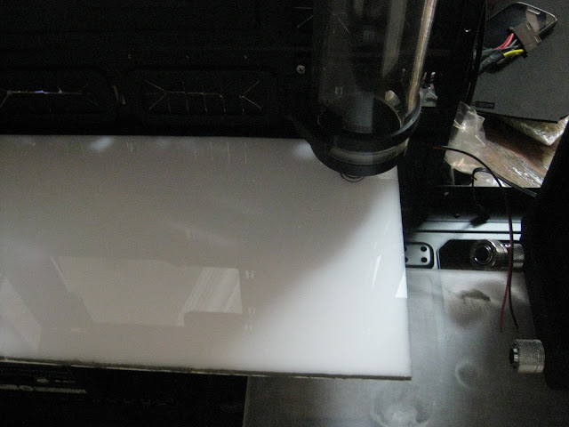
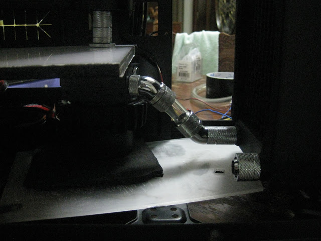
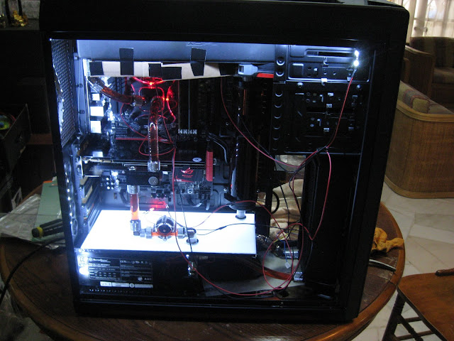
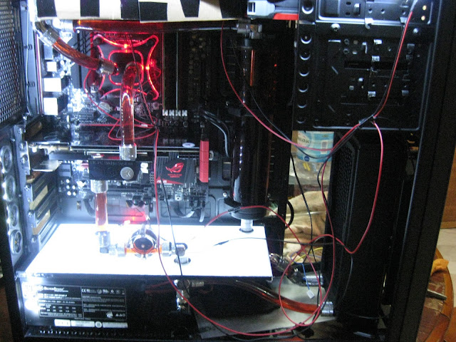
So my main objective was to get the pump directly under the reservoir but its super tight. As you can see there is no gap at all between the pump top & the luminous panel.
Another problem was the pump inlet fitting & the fillport is not aligned. The pump is a little too thick so it offsets outwards a little bit. And also the 45deg rotary isnt straight. I can solve it by rising the pump higher but I dont have space though to rise the pump so had to use 20mm extender at the radiator
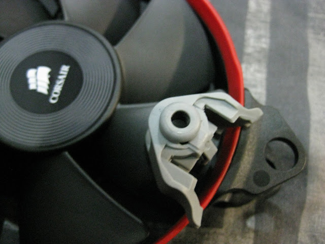
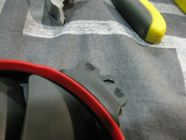
As for the pump offset problem, I had to use a dremel to grind the pump cover or whatever you call that round circle thing that secures the pump top & the pump. Basically I trim the gripping material a little bit so that the pump can enter inwards a little more. Sorry for not taking a lot of pictures, when it comes to modding, taking pictures is my less priority since I spend too much time doing the actual work
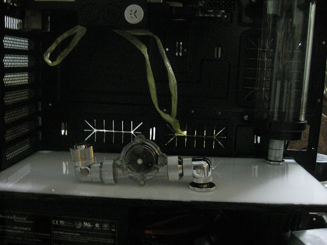
Made the 2nd fillport yay! My initial plan was to put this flowsensor at the reservoir inlet at the top & use extenders from the fillport to the bottom of the gpu inlet. So that I can run a straight tubing from the bottom to the gpu inlet. This will give the straight tubing that we usually see in acrylic tubing builds but then I thought why not replace the extenders with my flowsensor? Plus it will be easier to see on the luminous panel instead of the top & also save me from using extenders therefore less cost! That long extenders is just for aligning, will replace that with compression fitting & tubing.
I tell you, this is probably the hardest part in my build so far! First I need to attach the pump to the fillport at such a tight space, then from the fillport I need to connect to the reservoir at such a tight space to work with. Once everything is set, I had to connect this small piece of tubing to the radiator & oh boy...it was so hard! Because I cant move the pump or have enough space to work with. Took me more than 1 hour to get the lower portion done. I had to remove to rivets at the back of the casing to fit this luminous panel properly below the pci bracket & I also drilled 2 big holes at the bottom acrylic panel to route the pump wire from below the casing & also allow me to adjust the pump speed. Not convenient to adjust the speed from under the casing but at least I have the option if needed. I plan to connect this pump on a lamptron cw611 though so it will allow me to adjust the speed through the fan controller instead.
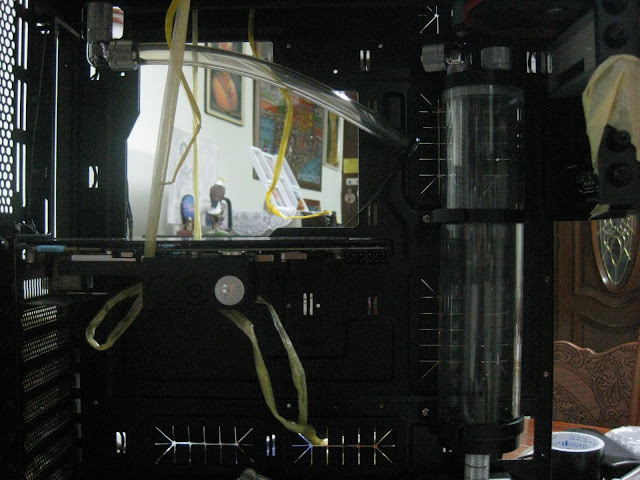
This is what you get when you dont have motherboard. Had to hang the gpu with strings to get the accurate measurement for the fillport locations.
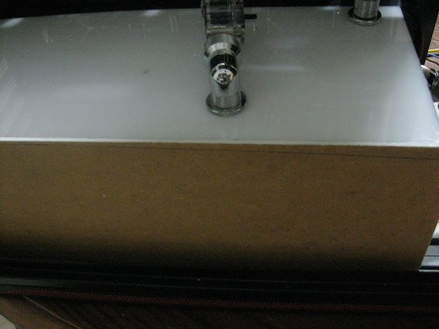
So far everything is looking good, will work on the psu side cover & at the front. Took me more than half a day to get the lower portion routing done. It looks simple but I did a lot of small modding here & there to get it in such a tight space.
The luminous panel is just a prototype though, but I dont plan to change it since is amount of work I need to remove the fittings & put it back is such a pain. If the led 1 day failed then only I will decide to create a new luminous panel with laser engraved instead of hand sanded for better light distribution. I also have an idea to make a aluminum bracket to fit the led inside whenever it fails, this will make the whole replacing led process easier. Basically what I mean is instead of using black tape to hold the led strip to the side of the acrylic, I will create a thin spacing with aluminum instead.
Not sure if you understand what I am trying to say but for now I think I will just use the current luminous panel.
Thanks to [@pristine] for borrowing me his hole saw
Making fillport will be super hard without it! But the hole saw is a little small for the bitspower diameter so I had to use grinding stone to sand the hole further so that the fillport can fit inside nicely. I know the holesaw was designed like that because when you make hole with metal, you can use the fill port threads to screw the fillport in but not with thick acrylic panels pristine, I will return it back to you soon
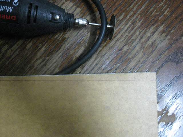
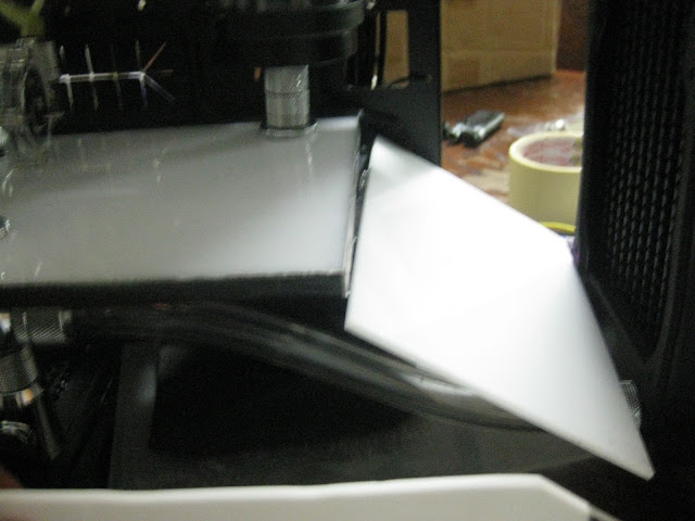
The side cover is a little high so I will need to trim it a little bit.
My design is to put another acrylic at this angle to help the airflow from the radiator.
Due to short acrylic panel, I had to glue another acrylic to it
I am going to cover it with matte black sticker so the colour dosen't matter. Most importantly is to make good use of the resources you have! Don't waste it
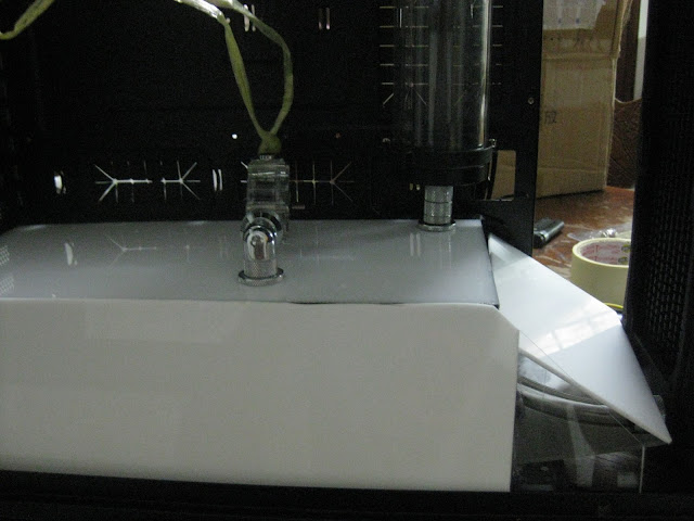
Done with the whole cover but I had to make a hole & attach a screw to keep the acrylic panel touching the luminous panel otherwise there will be a gap
Easy to remove too, so cable management from the psu shouldn't be a problem. Just pop it out & plug in hehehe
I know the side panel is not straight but this is probably the best I can do with a dremel. Once I put the sticker I think it wont be noticeable.
Now I need your suggestion, should I cover this part like below? Full cover or partial?
If I cover it fully then the 5.25" drive bay part also I will need to cover...
Or should I just cover the top part, meaning the radiator & sp120 fans will be visible. I plan to make an ROG logo ...still thinking which to go for since full acrylic cover is very common & everyone done that already. I am thinking of doing something different.
Got my vinyl from [@kray_keigo] today. Serious good high quality stuff :thumbs:
As you can see from the picture, my previous cut with the dremel wasn't that perfect. Shaky hands
so a quick fix with eproxy & you won't even notice it hehehe
My touch & go card definitely helped me in applying the sticker without bubbles
I am quite satisfied with the psu cover considering this was my first attempt, not so satisfied with the luminous panel yet as you all know but since this isn't a sponsored build or what sort, just my personal rig so who gives a fark
I can perfect the luminous panel but that would mean me taking apart the panel, unscrewing lots of fittings here & there that took me quite some time to get it in place with such a low clearance plus I might need to spend probably another RM50-100 to get the material, laser cutting etc so I think i'll pass.In case if there is a leak during the leak test somewhere under the psu cover & I couldn't fix it without taking apart then I might consider getting the luminous panel perfected. Lets just hope no leaks ya
Still deciding to go with 5.25" bay cover with acrylic + matte black sticker or acrylic + ROG logo. Once the side panel is on, there won't be any difference so I am still thinking on my options
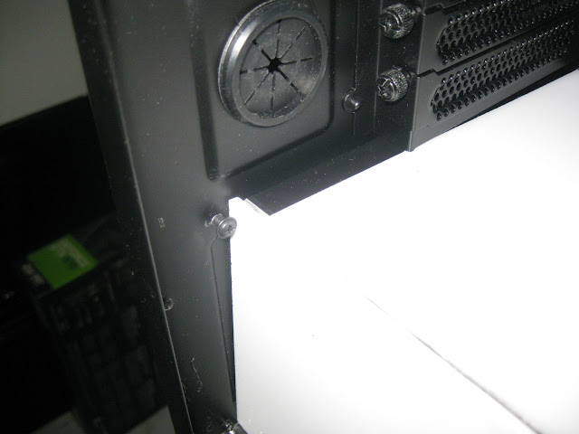
It's either bending the metal or cutting it off with a dremel. Went with the lazy method lol otherwise the acrylic panel wont be able to sit nicely over here.
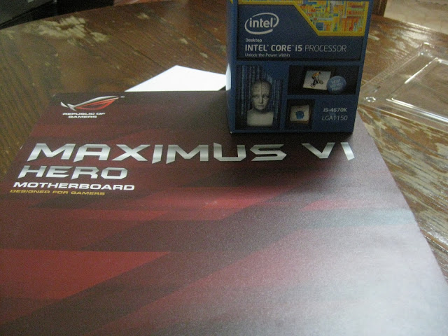
Hero & haswell is here, yeah I went for hero finally. Dont intend to wait for formula any longer plus I got hero from a friend at an attractive price
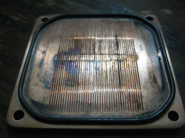
So I did the usual process, install cpu, mobo standoff etc..before putting on the waterblock with thermal paste I decided to open it to take a look inside & what a horror!!! Oxidation so badly, this is basically my fault though. I run the loop for 2days & drained it for some changes but didnt let the components to dry properly & just left it there to dry itself haha. Also if you notice the o-ring somehow left those black marks on the copper & it was hard to remove it even with vinegar. Not exactly sure what is going on but I hope it dosen't leak. o-ring condition is still good though...
The usual vinegar + warm water + lime solution
So since I am doing push + pull config, available space is quite tight considering I am using RX radiators. To make sure I have sufficient spacing, I made myself 120mm fan body to estimate the distance when installing my loop. This is because I dont have any 120mm fans spare & the sp120 fans I ordered will arrive in 3weeks time :lol:
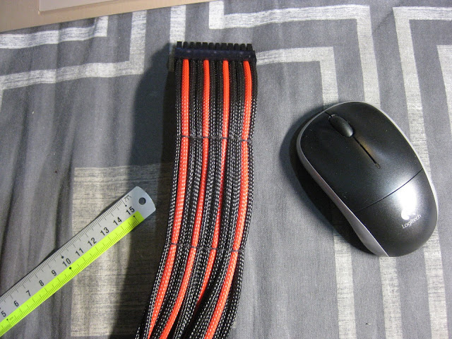
Started with cable sleeving, just the internal I/O cables only though, psu cables haven't yet and oh boy it was time consuming alright. Took me more than 2hours to get it done. Hard since I had to sleeving while standing & the cables are quite thick & of different sizes.
Current loop, short, simple & clean
I sleeved using MDPC sleeving & I find it way better than colortrail sleeving in quality wise. Colortrail is quite good too & most importantly cheap but MDPC is much easier to sleeve but too expensive lol. I almost used up all my sata sleevings already for the internal I/O cables such as usb cables, etc. Need to get more for the sata cables. I am a little OCD on stuff like these, I know you dont really need to sleeve it but thats just how I roll. Maybe I am a perfectionist?
ModMyToys pcb installed!
So yesterday I was sleeving the switch 810 front I/O cables & I used up most of the sata sleeving which was meant only for the sata cable. Sadly its enough to sleeve 1 sata cable only so now I got to order more.
I am using MDPC sleeving btw and the quality is top notch. Applied a little super glue to the sleeving & cable so that it will not come out no matter how hard I pull it. I had bad experience with previous sleeving I did on 24pin cables so this time I will be adding super glue to give that stronger hold.
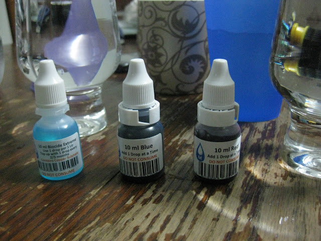
Time to start filling up the loop.
I plan to go for blood red colour to match the ROG theme.
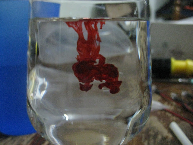
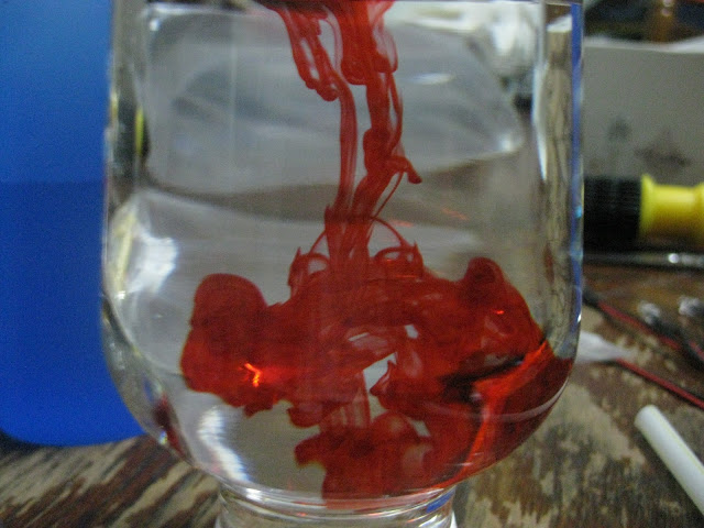
Just experimenting with how much dye I need.
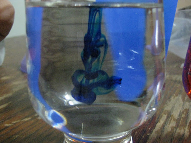
I only added 1 drop red & 1 drop blue but the liquid turned straight away to dark purple. This means the red ratio must be more than blue.
Sadly I was too confident & added lots of red & 1-3 drops of blue straight away into the loop. It straight away turned to purple. Now I got to drain the whole liquid & flush it with distilled water & get the ratio right. Learned my lesson lol, then I mixed the dye in a seprate 1.5 bottle first & started filling the loop from the bottle.
I got the colour that I need, the ratio I used was around 20drops of red & half a drop of blue. I drop the blue into a small glass of distilled water & slowly fill the water into the 20drops of red water. Used around half a glass so approximately only half a drop of blue is required.
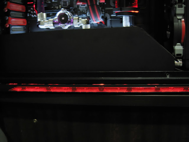
Upper part red looks fantastic but the luminous panel kinda make the red looks yellow/orange at the bottom part.
Ignore the cable mess, I am playing around with leds. Apperantly the 3mm & 5mm leds I bought was wrong, they are not giving constant light. The led is have the "pulse effect" blinks & dims, blinks & dims etc. This may be nice for some people but I dont really like it so I got to find the correct ones now haha.
So do you like my reservoir? I hope the tiny bubble stays hahaha it gives a really nice effect to it, but unfortunately there are few scratches on the res. Oh well, people are not going to stare at it too long anyways right?
I did some red touch up today, just to highlight more red colour in my build since its pretty dark atm. Sanding the pci bracket is a pain in the ass I tell you, wished I had some paint stripper lol.
Here is the optical bay cover. Its a temporary cover I think. I haven't decide yet should I make a big ass ROG logo at here or just mount ssd over here. Oh & yeah, I painted some screws hehe, looks nice isn't it...
Initially I was thinking to make a luminous panel to display the ROG logo in white + red like how kier did with his build, but then I am thinking if I were to get SSD then where should I mount it. You know you gotta "show off" if you are using SSD right. So I am still deciding. Sorry for this blurry picture, lazy to adjust the camera ISO haha
Also kustom pcs is out of lamptron CW611. Noooooo!! Gotta wait for them to restock D:<
Didnt had any progress last week because my father accident 2weeks ago so I was staying up night in the hospital. Another bad news is that the rig is partially done, so I been playing games on it. Finished far cry 3 on it but today when I was listening songs the display suddently just went off. Now there isnt any display from the graphic card. I think my graphic card died so will need to test it & most likely send to RMA. This is farked up :lol:
I am almost done with it, just left to install the remaining fans & make custom cables but shit happens. I was hoping to finish this build by end of this month but...
Anyways thanks to [@HoNeYdEwBoY] for the rams :wub: I didnt know the ram led has a pulse effect. I thought it was just a normal constant led (didnt read reviews :lol: ). Remember previously I had 3mm led for the raystorm & I didnt like the blinking effect, but since the ram has a nice pulse effect to it, I think maybe adding that blinking led to raystorm might match. Will test it & see how it goes
Sleeving the 3mm leds.
So I started adding fans on top & the standard 3cm radiator screws doesnt fit so I had to custom make my own screws that is slightly longer.
Started sleeving the fans too. Yes I am a perfectionist I guess, even fan cables I will sleeve even though its already black. Usually small touches like this can make a difference in a build.
Last edited: