Kei
Member
Scratch build valve amplifier
...or Valve amp if you're British. Those from OCUK may recognise this. It will be the abridged version rather than the entire saga. That said, even OCUK got a more brief version compared to the poor souls on DIYaudio who were a godsend helping me debug and get this beast working properly.
Something a little different from the usual pc builds. I've been trying to get both the time and effort to scratch build my own power amplifier for nearly a decade. Originally, I had planned on building a clone of a Quad 606, but owning and tinkering with 12 different solid state amplifiers, it just didn't really "spark" my enthusiasm enough so it got put on the back burner in 2012. Late last year a friend in work asked to borrow a scope probe as he was repairing his vintage valve amplifiers. (Leak TL12's) Which brought up the idea I'd never considered, why not scratch build a valve amp instead?
The plus points from my perspective were:
Disadvantages:
Having spent some time looking around for something to work with, I came across a book by the British valve manufacturer Mullard called, Circuits for audio amplifiers. In said book were a few different designs one of which piqued my interest, the 5-20, so named because it uses 5 valves and would happily produce 20W. It might not sound like much to some, but 20W is more than sufficient to shake the windows, rattle the furniture and severely annoy my neighbours. The topology was used in many successful commercial designs that are very well regarded. (Dynaco ST70, Harmon Kardon Citation V, Eico HF60 & Beam Echo Avantic DL7-35 to name a few)
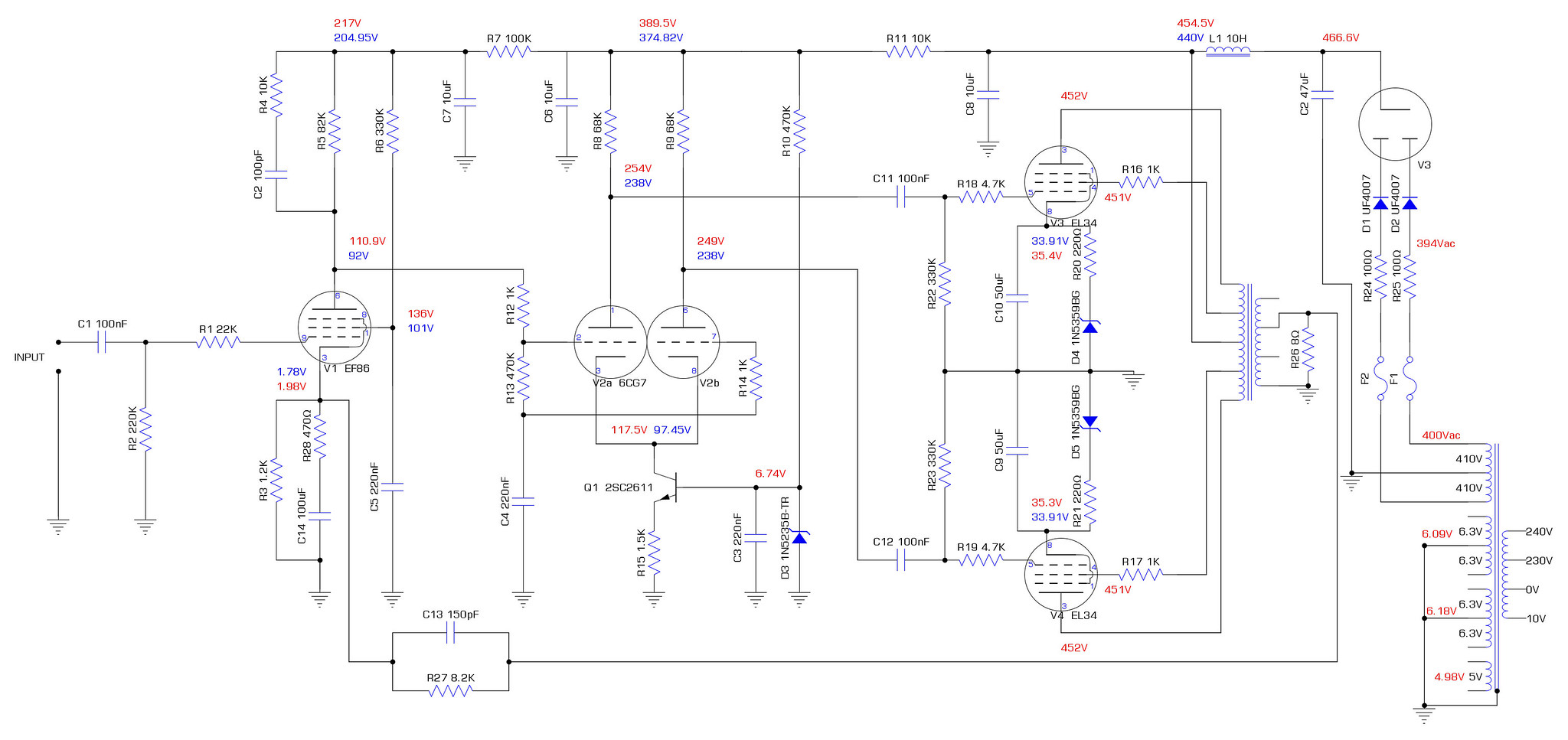
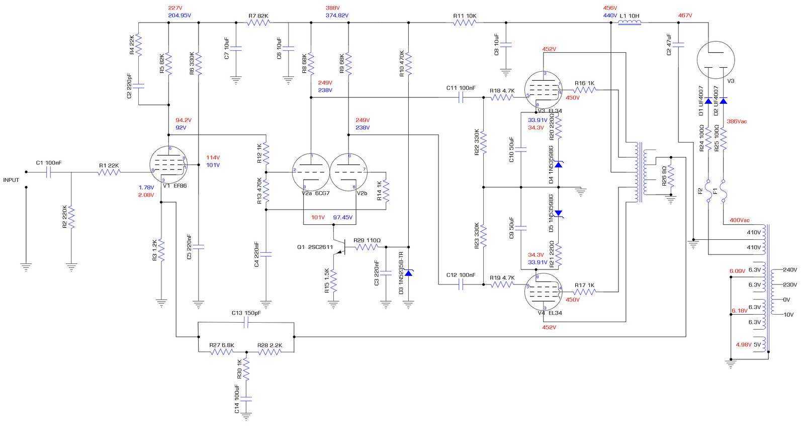
Schematic for said build.

I decided to approach the idea by designing and building a prototype to test the concept before committing to an exact design and paying for materials that may not work out. The first prototype was built from scraps of MDF as I had a load stored. By this point I had bought all the components including the rather excessively expensive transformers. Since the output transformers can make or break the sound of the whole amplifier, I opted for Sowter as they are renown for transformers that have vast bandwidth covering the audible range and beyond. The only off the shelf choke I could find that fits the design was from Variable Voltage Technology on the Isle of Wight. The HT transformer I chose a Primary Windings part as it was by spec the same as VVT but slightly cheaper with a decent reputation. So 2x Sowter UA-21 output transformers, 2x VVT VTL12158-1440 Chokes and 2x Primary Windings HT transformers were bought. (at considerable expense)
I tweaked schematic with altered fusing to improve safety and solid state diodes added to help protect the valve rectifier. (all provided by the helpful folk at diyaudio)

The standard Mullard tag board design.

My tweaked version to make for shorter and tidier cable routes between the board and the other components as I intended to build a different layout that is similar to their 5-10 amplifier.

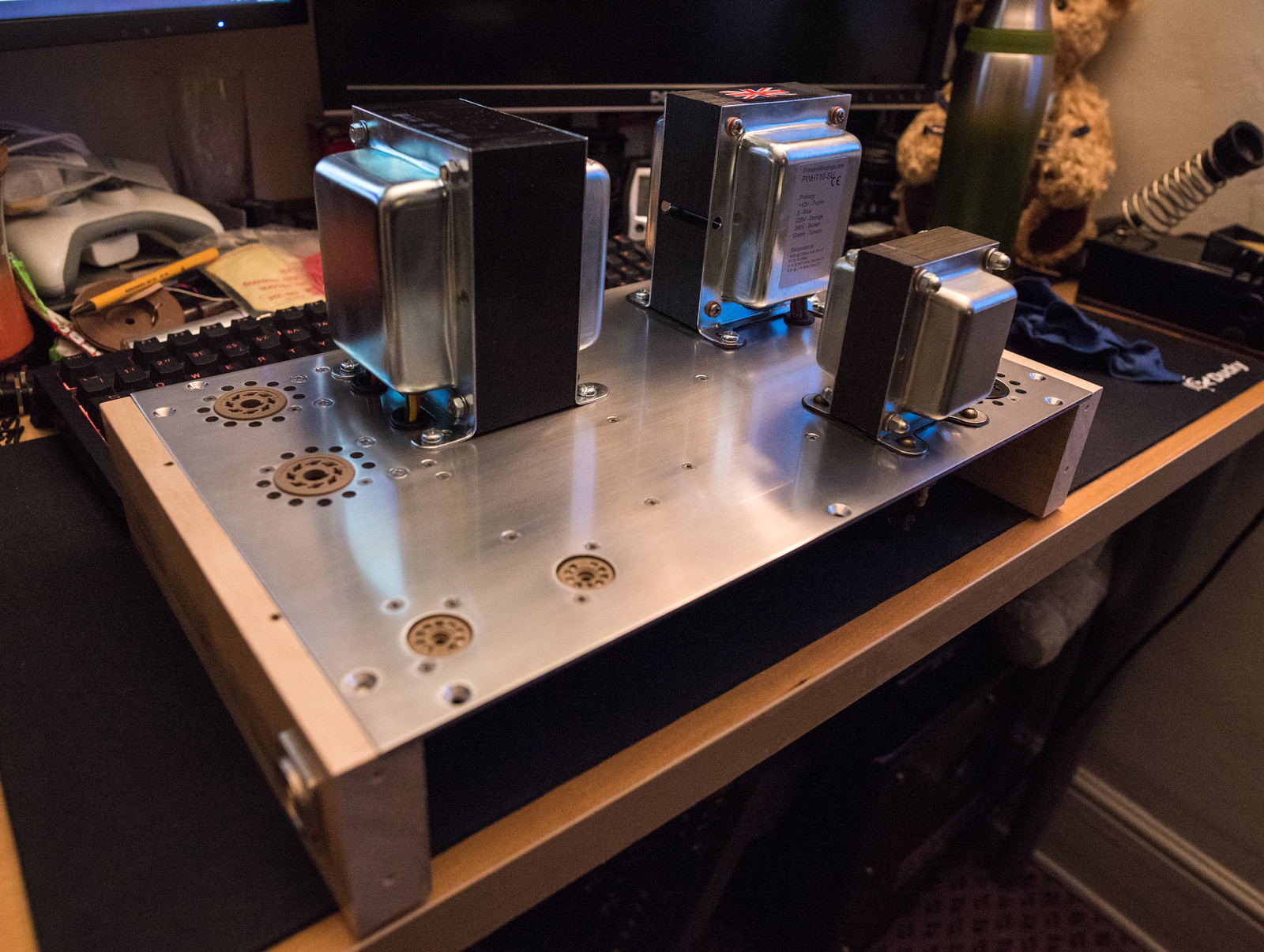
The board placed in with the other components in their approximate positions (where possible)

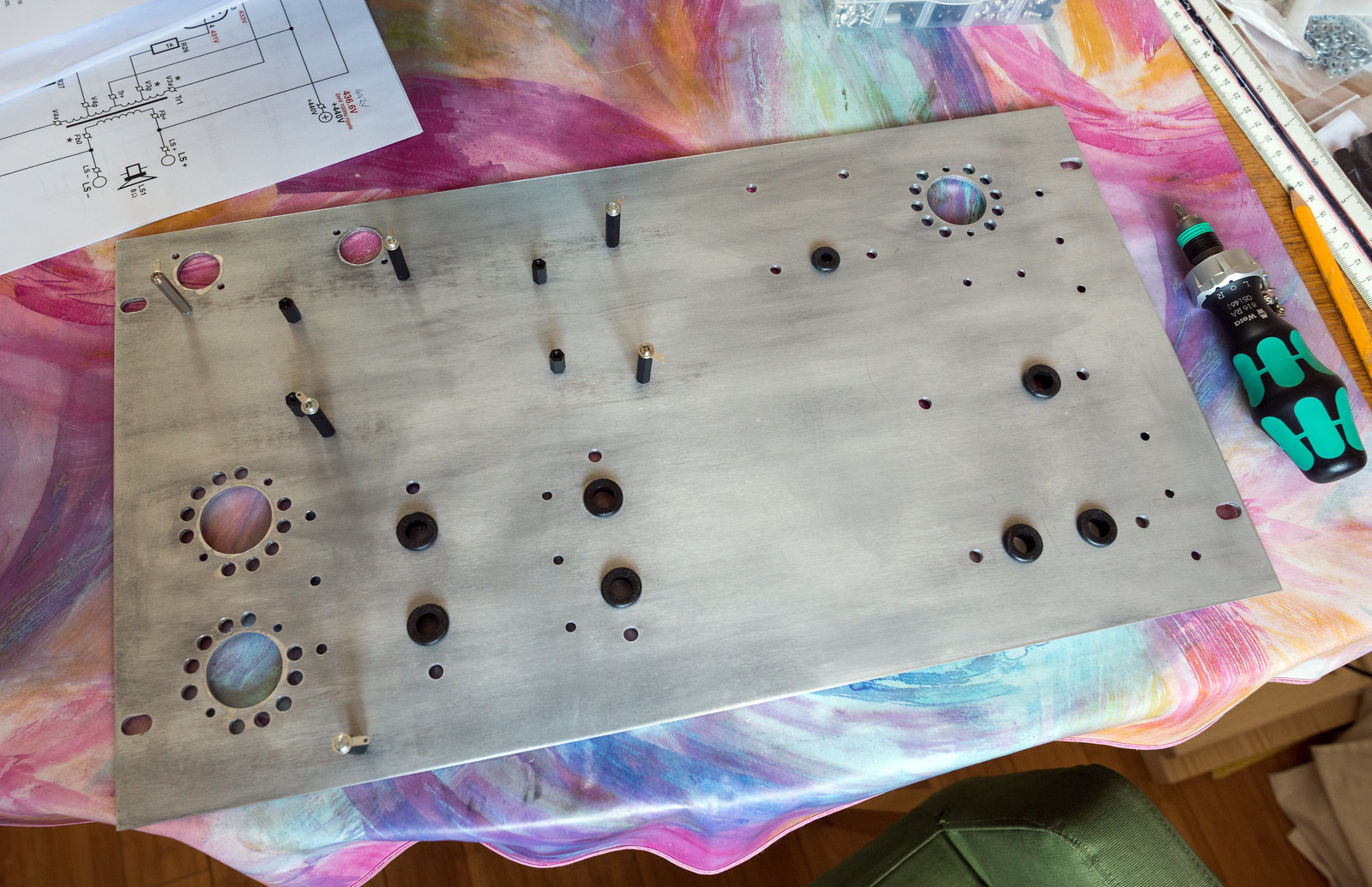
I then drew up a rough cad design to show the approximate finished design layout. The frame will be made from wood and the main base plate will be aluminium ~3mm thick. I'm thinking of using Shaeffer AG for machining a pair of panels for the final design.

I went for new old stock input valves in the form of GE 6267 for the EF86 (american equivalent) and a GE JAN 5751 in place of the ECC83/12AX7 dual triode phase splitter as it has a little bit less gain. Not sure who made the 6267 for GE as they are west German, but the 5751's are USA made. Hopefully the older valves will perform well.

For the output valves I went with new russian made Tung-Sol EL34B and Sovtek 5AR4 for the rectification.

Roughly laid out prior to the bulk of the components arriving


When the mountain of parts arrived, I quickly discovered the main filter capacitors were stud mount which wasn't mentioned in the datasheet for this particular size. I was very glad I was only building a prototype at that point.


Because of the capacitor mess up, I redesigned the layout.
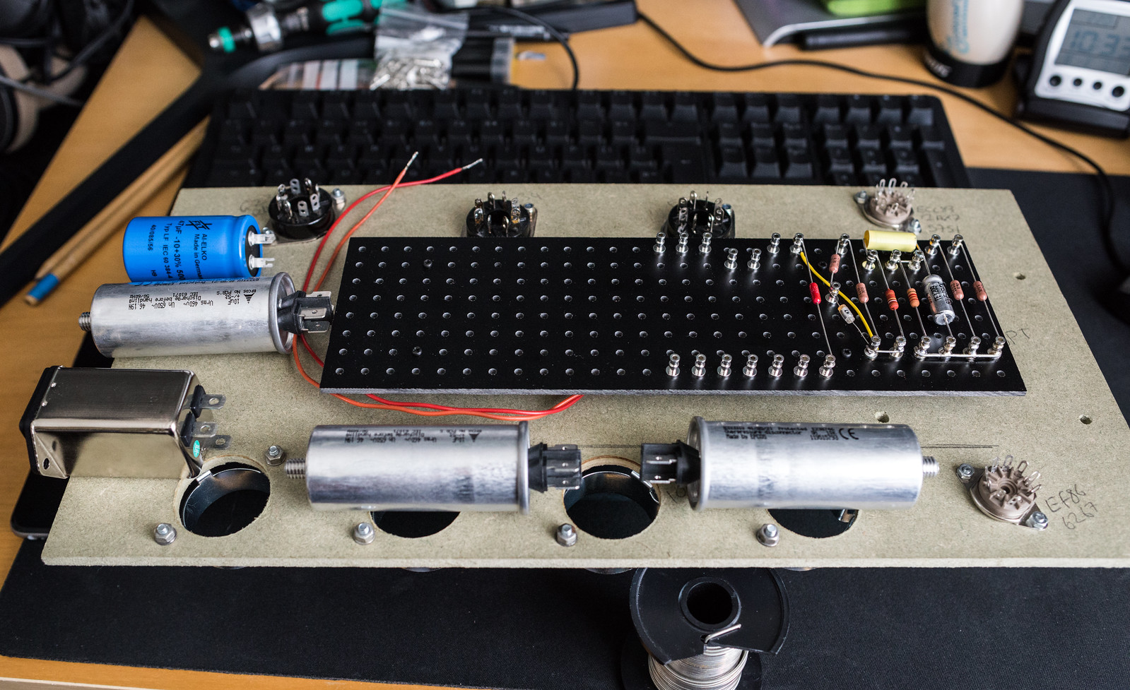
One finished turret board. (minus a capacitor I forgot to order) The astute may notice that I mounted everything upside down so the turret board connections were backwards. I had to pull everything off and flip it over.

Basically built and just needed wiring up.

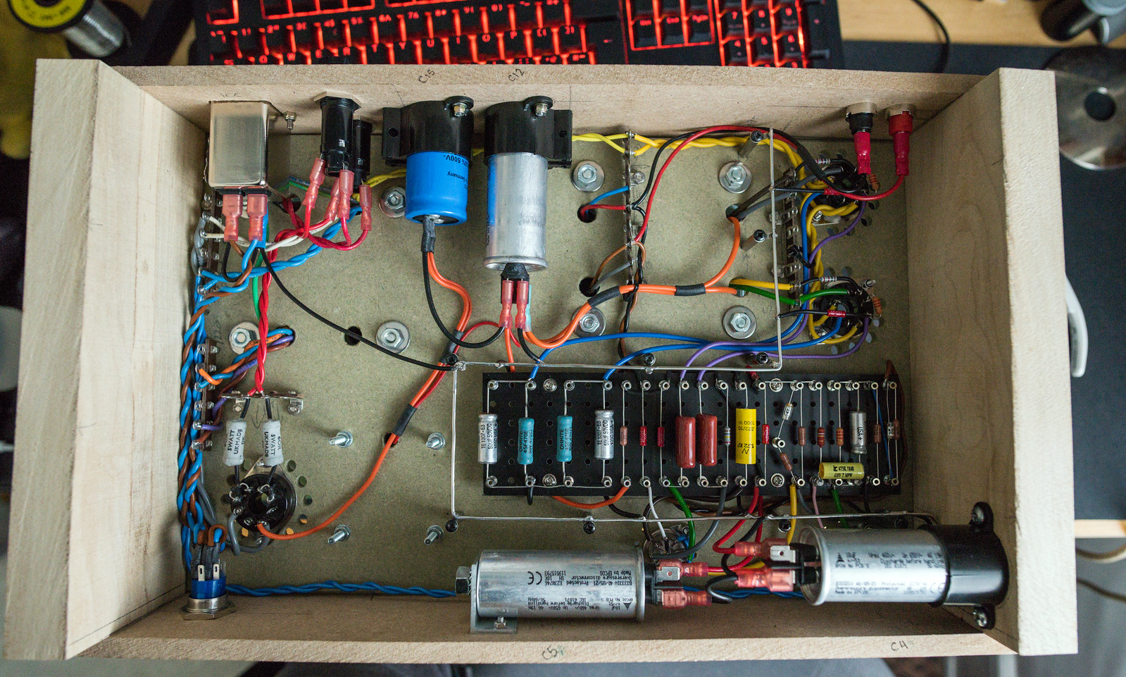
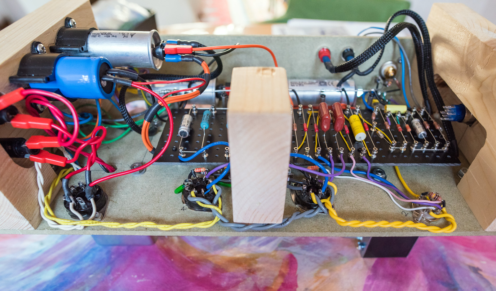
What with the compact design, it was a bit of a wiring nightmare. (the disadvantage of point to point designs)

Fitted 4mm banana sockets and a neutrik RCA

The wiring nightmare complete
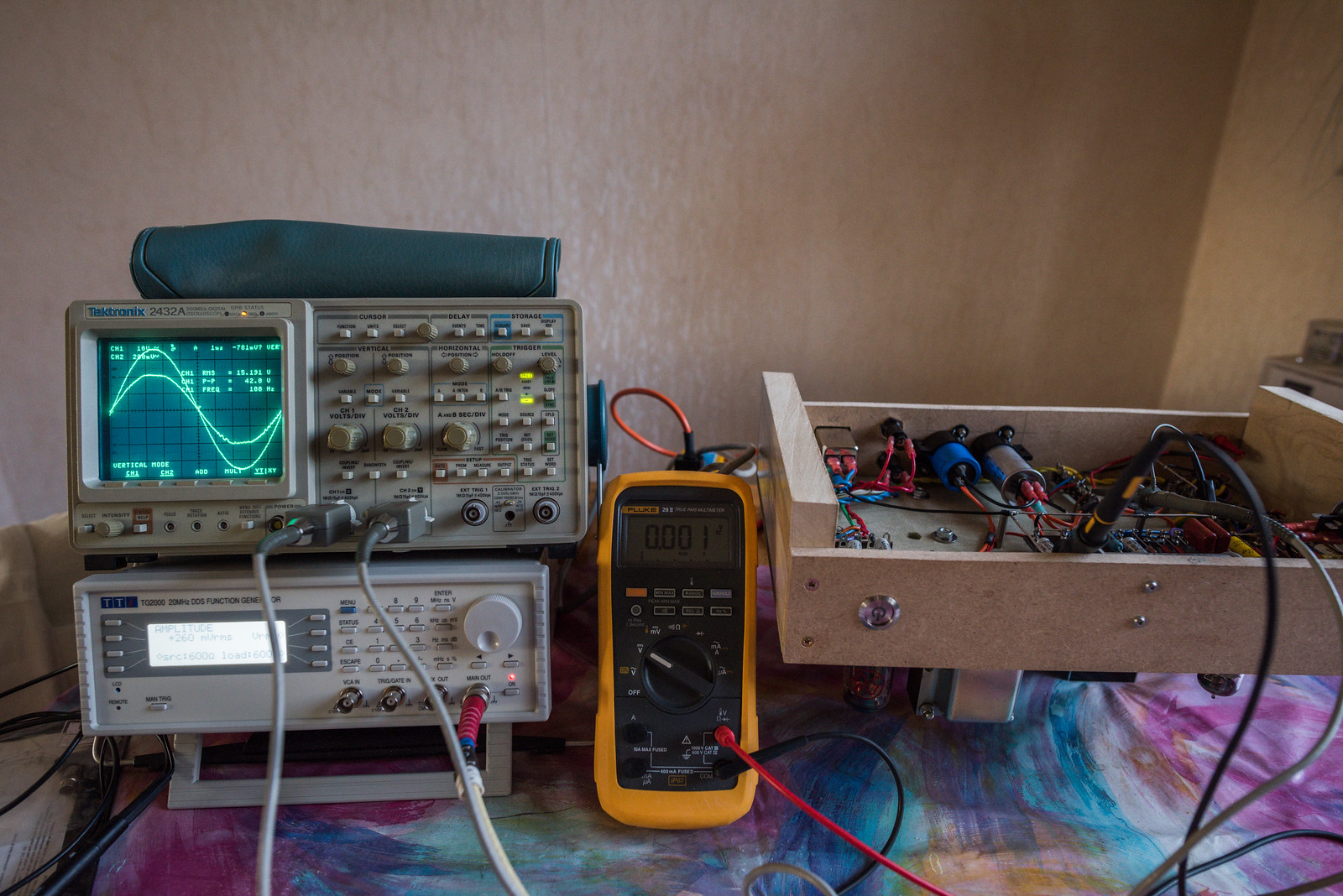
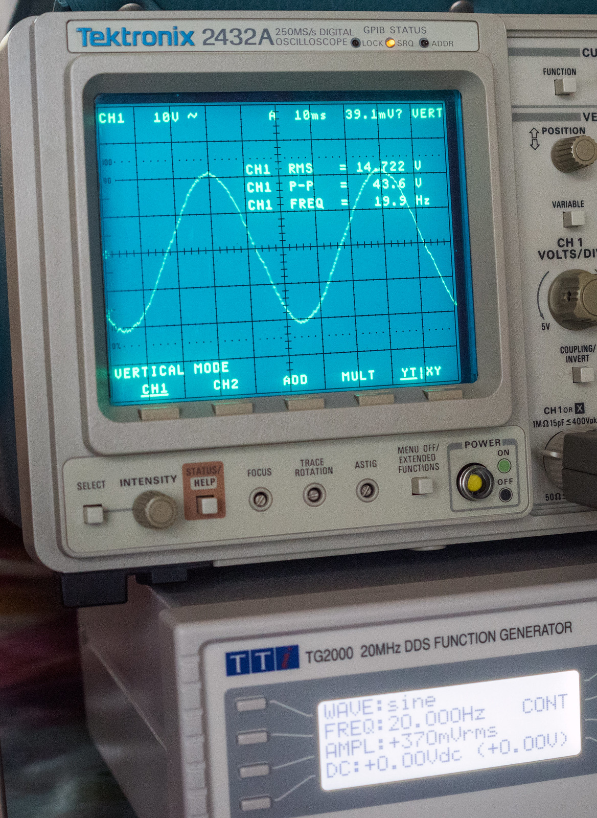
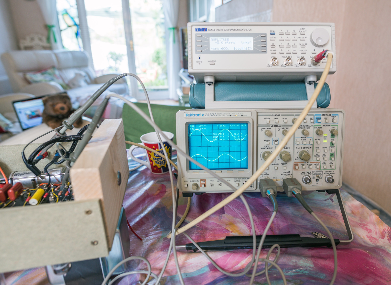
First test showed 39Hz square wave at 47V p-p with no input signal. I'd built a 35W oscillator. Turns out, I'd wired the anodes of the phase splitter to the wrong output valves so everything was 180 degrees out of phase making the negative feedback positive, hence the oscillation.

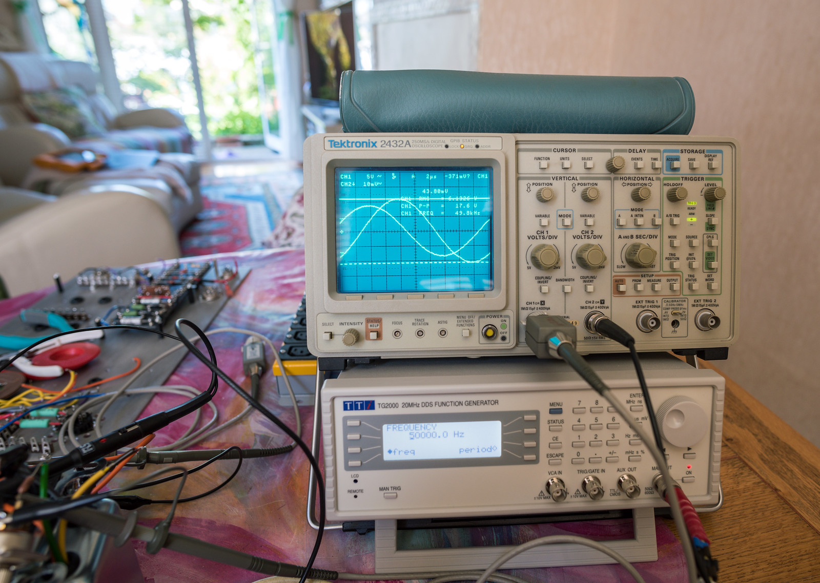
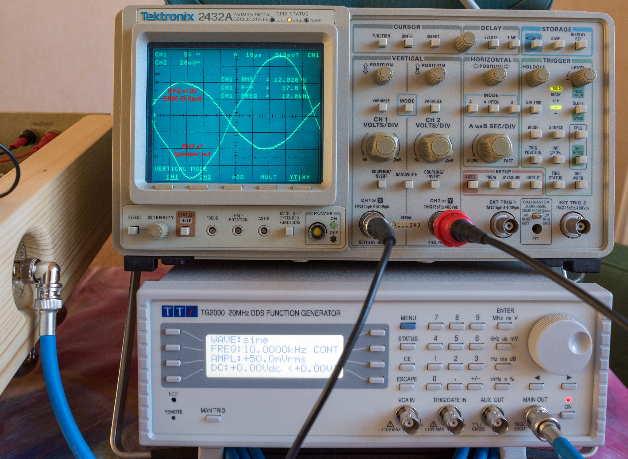
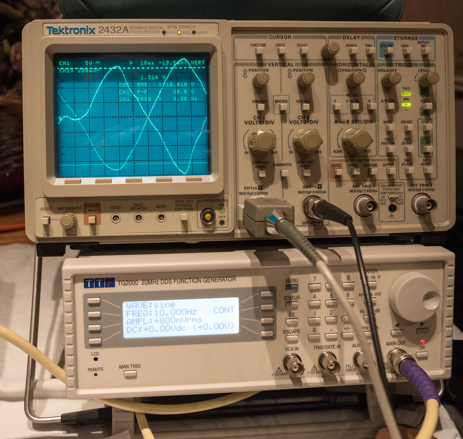
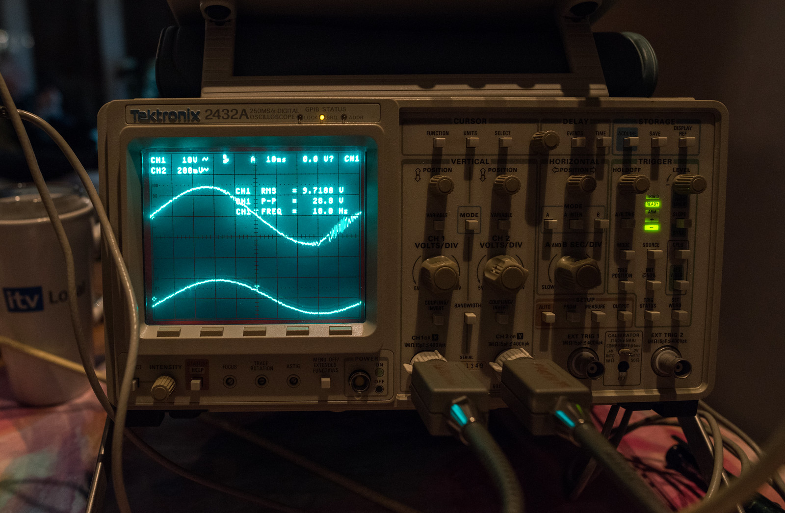
Disconnecting the feedback loop is a quick test to prove it all works as it should. I got a nice clean result. The gain was extreme. 0.05V input, 8V output. (that's 8W into 8 ohms)
I swapped the anode/UL connections between the two output valves to fix the phase issue. Re-tested it and no more oscillator. Voltages as measured at that point.

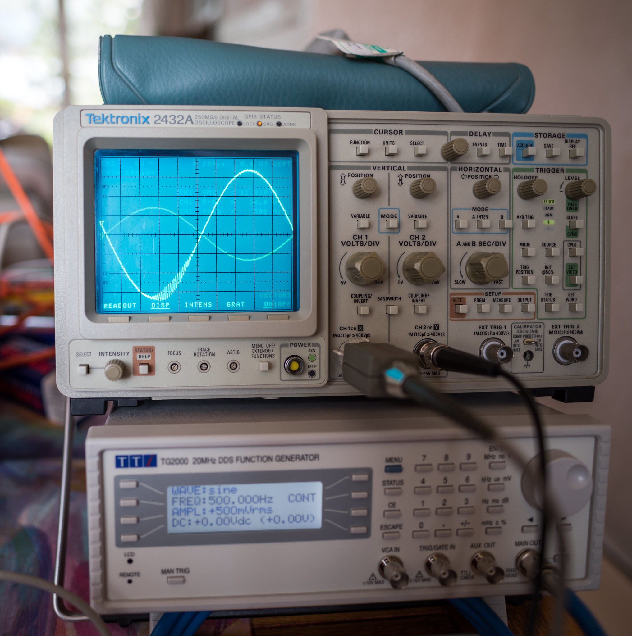
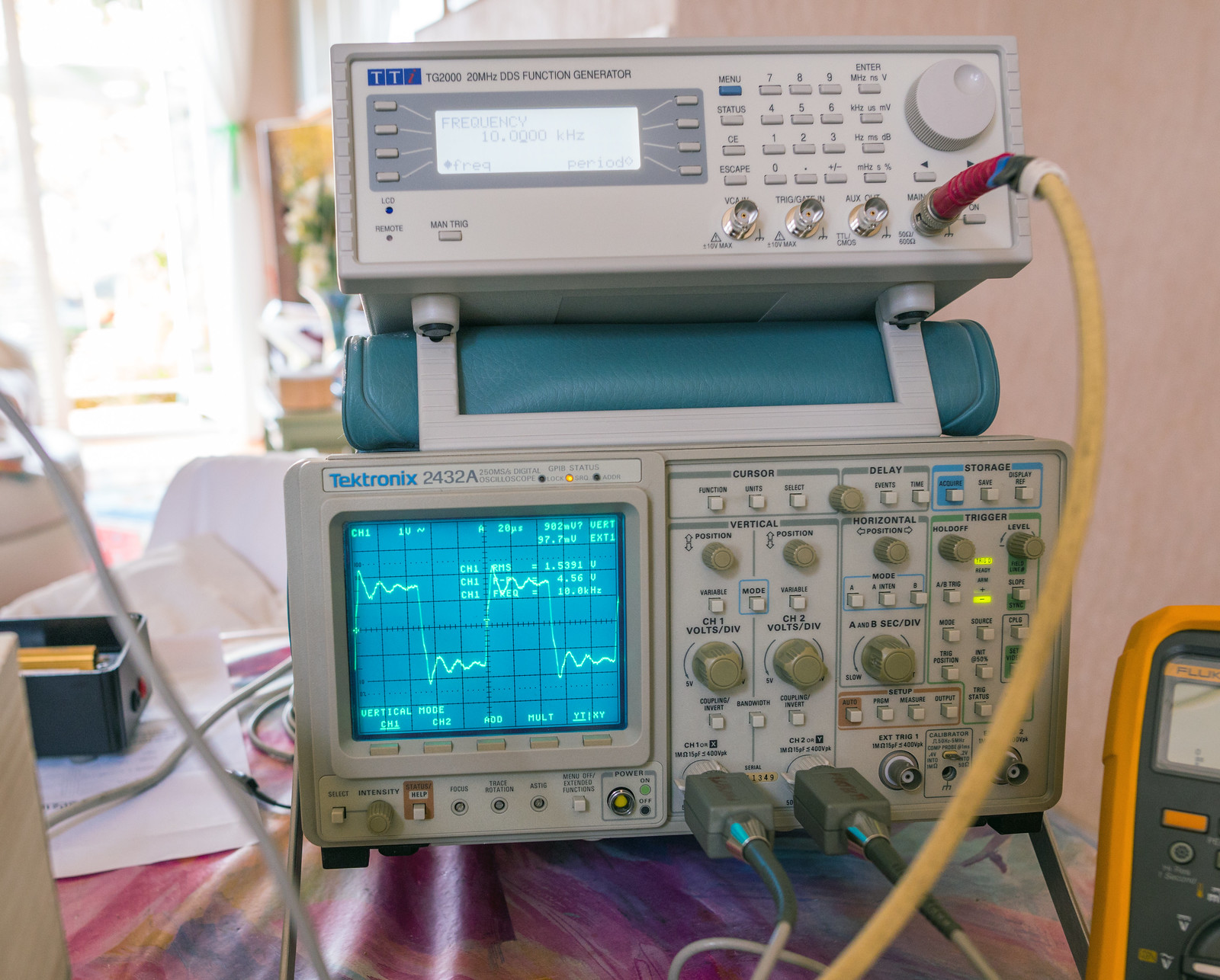
1KHz square wave input showed some ringing.

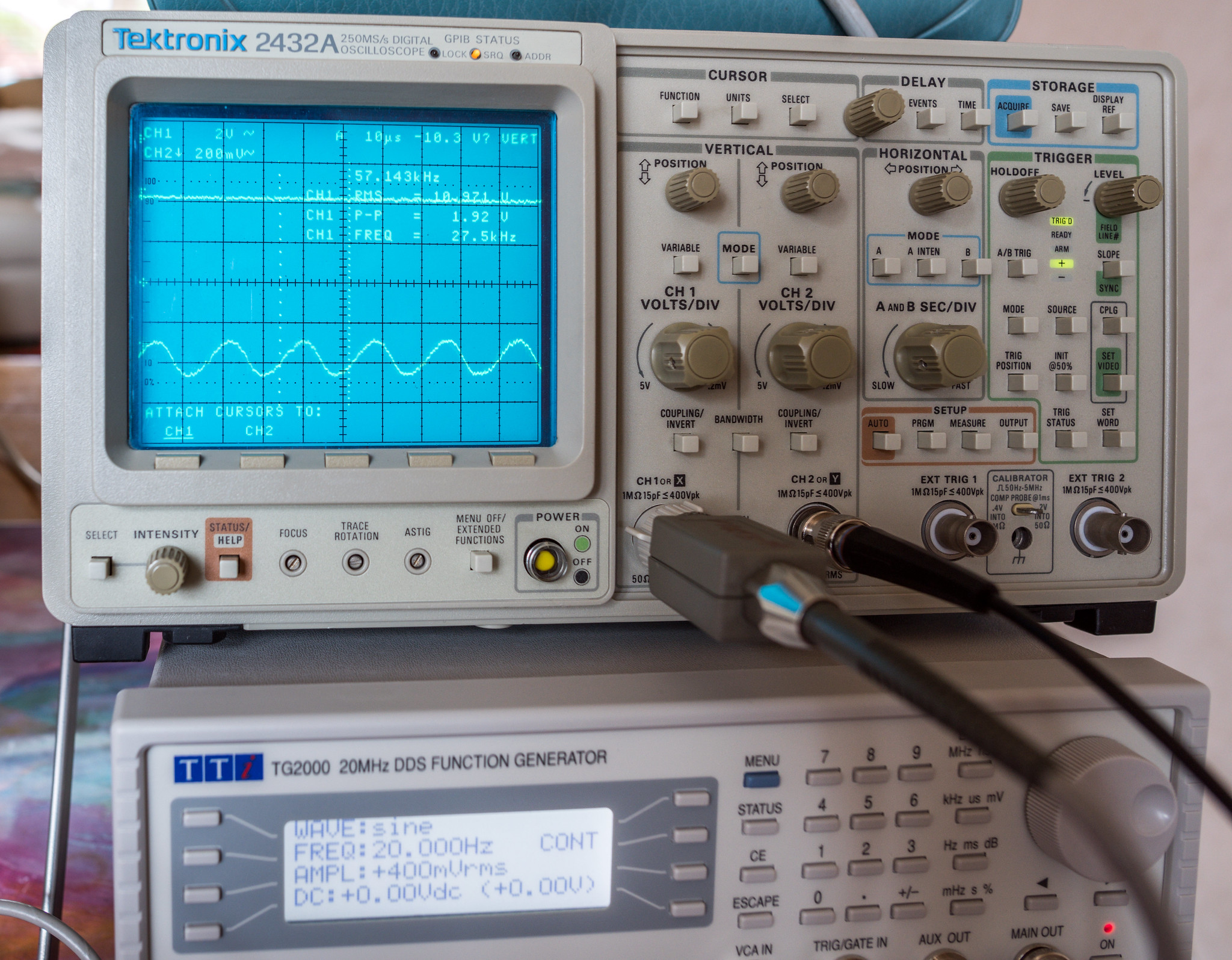
10KHz square wave input also showed more ringing.
The ringing was the sign that there were problems with stability. The design utilised a huge quantity of "global" negative feedback which includes the output transformer. Inevitable phase shifts resulting from the transformer reduce the stability margin. Too much phase shift combined with a lot of negative feedback results in oscillation. At the time, I wasn't as well versed in the whole affair as I am now.
The other problem I encountered was excessive dissipation, evident in a mild red glow to the anodes. (called red plating) This massively shortens valve lifespan so also needed fixing.

Since I was seeing around 20V more than I should have after the rectifier, my first place to look as was fitting some dropping resistors in the 410Vac feed to the rectifier. I spent some time going over the datasheet for GZ34/5AR4 and realised that there is a minimum resistance per plate that I'd not known about as it simply wasn't mentioned in the book.
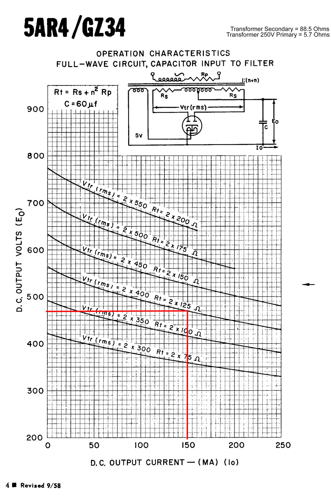
The valve wizard site also happened to have a handy formula for calculating it. (Rlim = Rsec + Rpri × (Vsec/Vpri)^2 + any extra resistance)
V Pri = 250
V Sec = 398
R Pri = 5.7
R Sec = 88.5
Result = 102.9464448
This put me a tad short of the 125 ohm minimum at 2x400V. (although they only list it for 60uF filter) I ended up fitting a pair of 5W 60R vintage RS branded resistors which I found in my stash of old components.

This reduced the issue but not quite eliminated, just a hint of a glow to the anodes. (dark grey metal structure inside the tube)

During further testing, I'd come up against a lot of oscillation problems. Most triggered by overload conditions or where the output transformer would start to approach saturation. You would expect to see distortion rather than severe ringing.

I thought a likely candidate causing the issue was my alteration to the layout and turret board, so set about building a Mk2 version which followed the standard design as closely as possible.
...or Valve amp if you're British. Those from OCUK may recognise this. It will be the abridged version rather than the entire saga. That said, even OCUK got a more brief version compared to the poor souls on DIYaudio who were a godsend helping me debug and get this beast working properly.
Something a little different from the usual pc builds. I've been trying to get both the time and effort to scratch build my own power amplifier for nearly a decade. Originally, I had planned on building a clone of a Quad 606, but owning and tinkering with 12 different solid state amplifiers, it just didn't really "spark" my enthusiasm enough so it got put on the back burner in 2012. Late last year a friend in work asked to borrow a scope probe as he was repairing his vintage valve amplifiers. (Leak TL12's) Which brought up the idea I'd never considered, why not scratch build a valve amp instead?
The plus points from my perspective were:
- They look and sound great according to the hifi world (although I'll admit I've never heard one, which inspires my curiosity)
- Point to point wiring with no printed circuit boards means very easy to modify, if a little more challenging to build
- Fewer parts, so less to go wrong, should make fault finder much easier
- Valves are more resilient to problems in the circuit and are less likely to catastrophically fail unlike transistors and mosfets
- Valves are still in production so no issues buying parts (unlike certain older mosfets/transistors)
Disadvantages:
- Transformers and chokes used can cost a small fortune
- Valves aren't dirt cheap like transistors
- Valves wear out with use
- Valves can be susceptible to external noise and can be microphonic
- The high voltages used require considerable care to avoid an early departure from this world
Having spent some time looking around for something to work with, I came across a book by the British valve manufacturer Mullard called, Circuits for audio amplifiers. In said book were a few different designs one of which piqued my interest, the 5-20, so named because it uses 5 valves and would happily produce 20W. It might not sound like much to some, but 20W is more than sufficient to shake the windows, rattle the furniture and severely annoy my neighbours. The topology was used in many successful commercial designs that are very well regarded. (Dynaco ST70, Harmon Kardon Citation V, Eico HF60 & Beam Echo Avantic DL7-35 to name a few)
Schematic for said build.
I decided to approach the idea by designing and building a prototype to test the concept before committing to an exact design and paying for materials that may not work out. The first prototype was built from scraps of MDF as I had a load stored. By this point I had bought all the components including the rather excessively expensive transformers. Since the output transformers can make or break the sound of the whole amplifier, I opted for Sowter as they are renown for transformers that have vast bandwidth covering the audible range and beyond. The only off the shelf choke I could find that fits the design was from Variable Voltage Technology on the Isle of Wight. The HT transformer I chose a Primary Windings part as it was by spec the same as VVT but slightly cheaper with a decent reputation. So 2x Sowter UA-21 output transformers, 2x VVT VTL12158-1440 Chokes and 2x Primary Windings HT transformers were bought. (at considerable expense)
I tweaked schematic with altered fusing to improve safety and solid state diodes added to help protect the valve rectifier. (all provided by the helpful folk at diyaudio)
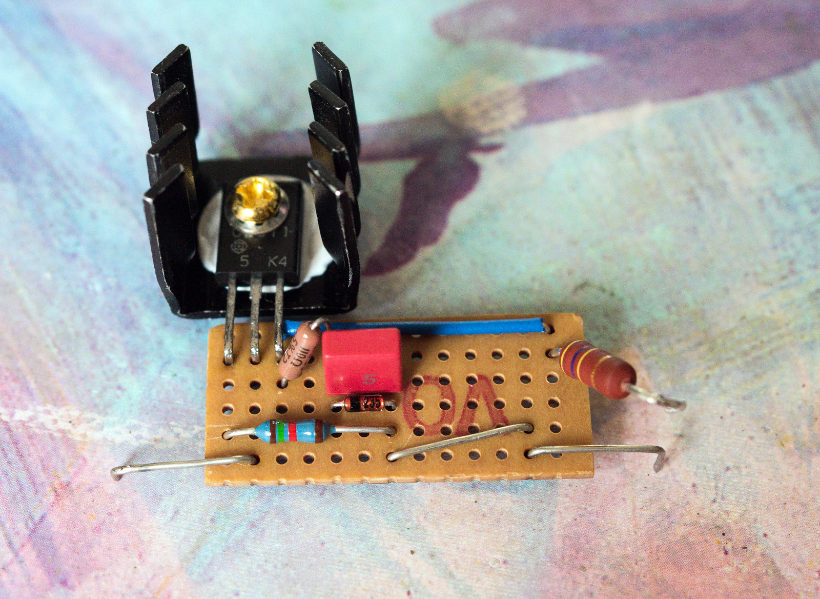
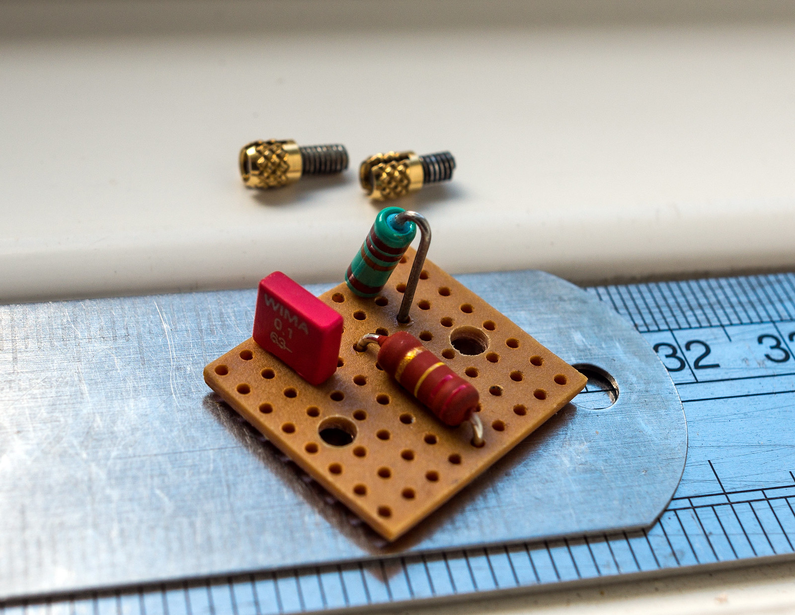
The standard Mullard tag board design.
My tweaked version to make for shorter and tidier cable routes between the board and the other components as I intended to build a different layout that is similar to their 5-10 amplifier.
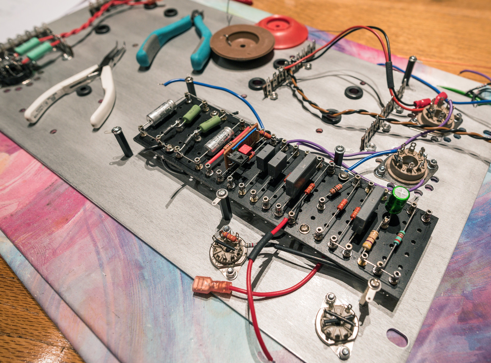
The board placed in with the other components in their approximate positions (where possible)
I then drew up a rough cad design to show the approximate finished design layout. The frame will be made from wood and the main base plate will be aluminium ~3mm thick. I'm thinking of using Shaeffer AG for machining a pair of panels for the final design.
I went for new old stock input valves in the form of GE 6267 for the EF86 (american equivalent) and a GE JAN 5751 in place of the ECC83/12AX7 dual triode phase splitter as it has a little bit less gain. Not sure who made the 6267 for GE as they are west German, but the 5751's are USA made. Hopefully the older valves will perform well.
For the output valves I went with new russian made Tung-Sol EL34B and Sovtek 5AR4 for the rectification.
Roughly laid out prior to the bulk of the components arriving
When the mountain of parts arrived, I quickly discovered the main filter capacitors were stud mount which wasn't mentioned in the datasheet for this particular size. I was very glad I was only building a prototype at that point.
Because of the capacitor mess up, I redesigned the layout.
One finished turret board. (minus a capacitor I forgot to order) The astute may notice that I mounted everything upside down so the turret board connections were backwards. I had to pull everything off and flip it over.
Basically built and just needed wiring up.
What with the compact design, it was a bit of a wiring nightmare. (the disadvantage of point to point designs)
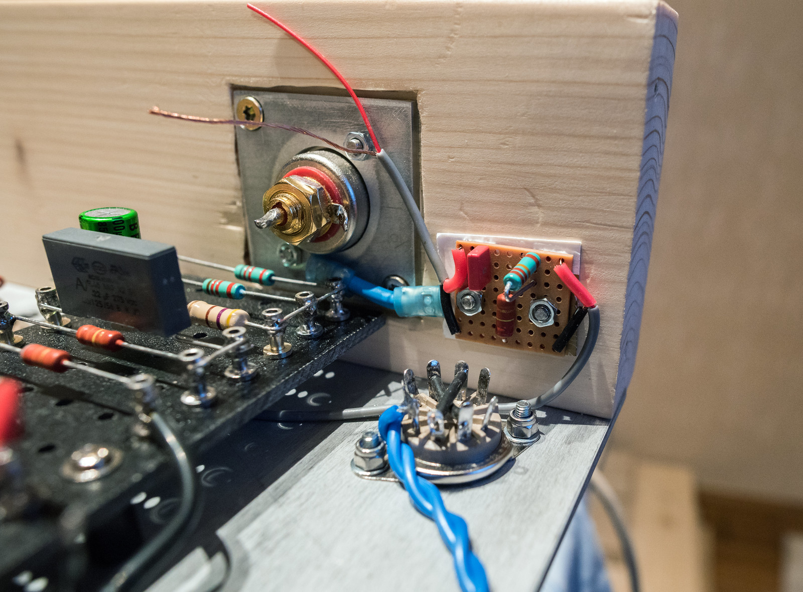
Fitted 4mm banana sockets and a neutrik RCA
The wiring nightmare complete
First test showed 39Hz square wave at 47V p-p with no input signal. I'd built a 35W oscillator. Turns out, I'd wired the anodes of the phase splitter to the wrong output valves so everything was 180 degrees out of phase making the negative feedback positive, hence the oscillation.
Disconnecting the feedback loop is a quick test to prove it all works as it should. I got a nice clean result. The gain was extreme. 0.05V input, 8V output. (that's 8W into 8 ohms)
I swapped the anode/UL connections between the two output valves to fix the phase issue. Re-tested it and no more oscillator. Voltages as measured at that point.
1KHz square wave input showed some ringing.
10KHz square wave input also showed more ringing.
The ringing was the sign that there were problems with stability. The design utilised a huge quantity of "global" negative feedback which includes the output transformer. Inevitable phase shifts resulting from the transformer reduce the stability margin. Too much phase shift combined with a lot of negative feedback results in oscillation. At the time, I wasn't as well versed in the whole affair as I am now.
The other problem I encountered was excessive dissipation, evident in a mild red glow to the anodes. (called red plating) This massively shortens valve lifespan so also needed fixing.
Since I was seeing around 20V more than I should have after the rectifier, my first place to look as was fitting some dropping resistors in the 410Vac feed to the rectifier. I spent some time going over the datasheet for GZ34/5AR4 and realised that there is a minimum resistance per plate that I'd not known about as it simply wasn't mentioned in the book.
The valve wizard site also happened to have a handy formula for calculating it. (Rlim = Rsec + Rpri × (Vsec/Vpri)^2 + any extra resistance)
V Pri = 250
V Sec = 398
R Pri = 5.7
R Sec = 88.5
Result = 102.9464448
This put me a tad short of the 125 ohm minimum at 2x400V. (although they only list it for 60uF filter) I ended up fitting a pair of 5W 60R vintage RS branded resistors which I found in my stash of old components.
This reduced the issue but not quite eliminated, just a hint of a glow to the anodes. (dark grey metal structure inside the tube)
During further testing, I'd come up against a lot of oscillation problems. Most triggered by overload conditions or where the output transformer would start to approach saturation. You would expect to see distortion rather than severe ringing.
I thought a likely candidate causing the issue was my alteration to the layout and turret board, so set about building a Mk2 version which followed the standard design as closely as possible.
Last edited: