That looks like the wrong switch for the job to me, the 5-pin ones are generally momentary action (they stay depressed once switched). Like a light switch that stays in it's on position unlike an on/off switch which just briefly shorts two motherboard pins.
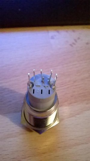
It should be obvious-ish from the markings how it works. The +/- will refer to the LED, which in this case looks like the outer two pins. In general the other 3 pins are C, NO and NC in the following order...
Extreme Left - Negative LED
Left - Switch Common (Ground)
Middle - Switch Normally Open
Right - Switch Normally Closed
Extreme Right - Positive LED
So wire the LED the only way you can and put the two power I/O wires from your motherboard on the centre and left pin (closest to neg LED). But don't leave the switch depressed. Pretty sure that will work but really you want a 4-pin switch.
JR
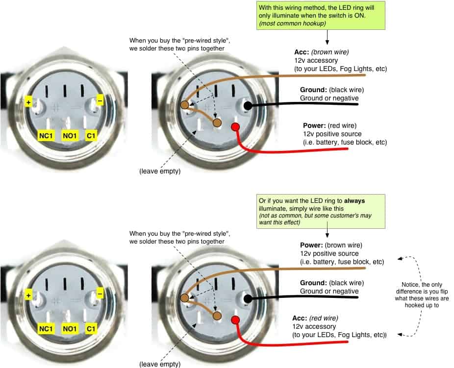
Edit: Some of the parts on Wraiths drawing are unnecessary and just make it confusing, there should be no need to connect two pins to each other as the motherboard will have a pair of power LED pins already.
")